2AUGO-T4An automated solar panel cleaning robot with a sub giga communication chip.
Ecoppia Scientific Ltd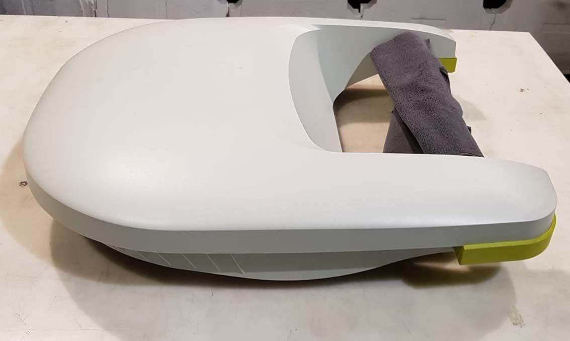
Click to zoom
Application Details
- Equipment Class
- DXX - Part 15 Low Power Communication Device Transmitter
- Date of Grant
- Jan 08, 2020
- Application Purpose
- Original Equipment
- Date of Application
- Jan 08, 2020
- Equipment Note
- An automated solar panel cleaning robot with a sub giga communication chip.
- Frequency Range
- 902.00000000 - 928.00000000
- Company
- Ecoppia Scientific Ltd
- Country
- Israel
Documents & Files
Document Text
Text extracted from the exhibit documents filed with the FCC. Open a document above to read the original.
Users Manual
ECOPPIA PROPRIETARY. This document and its accompanying elements, contain ECOPPIA information which is proprietary and confidential. Any disclosure, copying, distribution or use is prohibited if not otherwise explicitly agreed with ECOPPIA in writing. T4-5.3 Robot User Manual - WP6001_01 Only a qualified and certified Ecoppia worker may operate the T4 robot T4 User Manual |WP6001 Version 1 Valid as of 11 November 2019 P a g e 2 | 7 C O N F I D E N T I A L Table of Contents 1 General ................................................................................................................... 3 2 Safety Instructions – Working in a solar site ........................................................... 3 3 Setting Robot on array ............................................................................................ 4 4 T4 Digital Setting ..................................................................................................... 6 5 T4 Power Consumption .......................................................................................... 6 6 FCC Class A Warning ............................................................................................... 6 7 FCC Regulatory Notices ........................................................................................... 7 8 FCC Modification Statement ................................................................................... 7 Written by Batia Kwintner 11 November 2019 Batia Approved by Coo Eran Dgani 11 November 2019 Eran N a m e D a t e S i g n a t u r e Ver. Change Description Date Approved by 01 First edition 11 November 2019 Dgani Eran COO T4 User Manual |WP6001 Version 1 Valid as of 11 November 2019 P a g e 3 | 7 C O N F I D E N T I A L 1 General The T4 Robot is designed for cleaning tracker modules systems. During production hours, the robot parks in a designated parking platform, attached to the trackers row. The parking platform consists of 2 solar modules, the robots self-charging mechanism. The parking rotates with the row, tracking the suns position. During midday, the robot shifts sides on the parking platform, positioning itself so the charging poles, on its front, will always lean against the peripheral rail in the parking, allowing its batteries to be charged from the electricity flowing from the parking modules. After production hours, the row balances to a horizontal position, enabling the T4 robot to leave the parking and clean the row. 2 Safety Instructions – Working in a solar site Work is carried out within a solar site, generating electricity in direct current (DC). Throughout production hours, there is constant voltage in all cables deployed on the site. 1. Entry to the site will only take place after you have been instructed by the sites safety supervisor. 2. Do not work below the panels array. 3. Do not make any changes to the solar array. 4. Ensure no damage done to arrays solar modules during T4 installation. 5. Only a trained employee may perform the required operations on the site. 6. For any safety concerns - contact the field safety supervisor. 7. Beware electrocution from solar modules wiring and connections, in case they are damaged or exposed. Only a qualified and certified Ecoppia worker may operate the T4 robot T4 User Manual |WP6001 Version 1 Valid as of 11 November 2019 P a g e 4 | 7 C O N F I D E N T I A L 3 Setting Robot on array 1. Open T4 packing box in correct position, with "up" sign in upper direction. 2. Remove robot carefully from box and lay on a clean surface or directly onto docking platform. 3. Position the robot on the WEST docking side, in afternoon hours, while this docking side is accessible. 4. Notice: The T4 robot docking station contains 2 photovoltaic modules, set into the metal docking surface. Both modules generate 12 Volt 2.6- 7.3 Ah, transferred to east and west rails on docking platform. 5. Place T4 robot on the tilted docking surface, "charging poles" leaning against western charging docking rod. Ensure that the stopper rail prevents it from rolling off the table. 6. Attention: Do not hold both docking poles on robot while docking/ charging. This will close an electrical circuit and may result minor shock (12V 10Ah) T4 User Manual |WP6001 Version 1 Valid as of 11 November 2019 P a g e 5 | 7 C O N F I D E N T I A L 7. Remove T4 robots cover, lifting front bumpers first, carefully releasing them from lower bumpers. 8. Connect T4 battery to black and red related wires. This action will generate the docking magnet to rotate and lock into docking surface. 2 led lights on control card will lite to indicate the connectivity. In case this procedure does not lower the magnet, disconnect, press the reset button and repeat to connect the battery. 9. Replace T4 cover. Step 1 - Lift front cover Step 2 - Lift cover from rear Connect battery to control card wire Indication leds Reset button T4 User Manual |WP6001 Version 1 Valid as of 11 November 2019 P a g e 6 | 7 C O N F I D E N T I A L 4 T4 Digital Setting 10. Configure robot on "Master Control" window and "DCT" (Ecoppia Direct Connection array construction. T4 is configured with site relative software. 11. Enter Robot & row relationship into Salesforce system. Operating Manuals for T4, configuration and data input are available only to Ecoppia technicians and are confidential. 5 T4 Power Consumption The T4 operates on a 12V battery and has a peak consumption of 7.3Amp with average current consumption of 2.6A while working, 0.1A while parking. The communication module CC1310 from TI, is powered by a 3.3V power regulator and a maximum current draw of 25.1mA. References: TI module: http://www.ti.com/lit/ds/symlink/cc1310.pdf article, note that the part is suitable for systems targeting compliance with FCC CFR47 Part 15 (US) - 5.4 p.16 for power consumption, 5.8 p.25 for maximum transmitted power. 6 FCC Class A Warning The FCC wants you to know: This equipment has been tested and found to comply with the …
Text truncated - open the document above for the full version.
Attestation Statements
January 6, 2020 -------------------------------------------------------------------------------------------------------------------------------- 1 ‐‐‐‐‐‐‐‐‐‐‐‐‐‐‐‐‐‐‐‐‐‐‐‐‐‐‐‐‐‐‐‐‐‐‐‐‐‐‐‐‐‐‐‐‐‐‐‐‐‐‐‐‐‐‐‐‐‐‐‐‐‐‐‐‐‐‐‐‐‐‐‐‐‐‐‐‐‐‐‐‐‐‐‐‐‐‐‐‐‐‐‐‐‐‐‐‐‐‐‐‐‐‐‐‐‐‐‐‐‐‐‐ Ecoppia Scientific Ltd. | 89 Medinat Hayehudim, P.O. Box 12297, Herzlia Israel 4673300 Phone: +972 (0)9 8917000 Fax: +972 (0)9 8917001 Office of Engineering Technology Federal Communications Commission 7435 Oakland Mills Road Columbia, MD 21046 USA Date: January 2 nd , 2020 Subject; Request for Confidentiality FCC ID: 2AUGO-T4 To Whom It May Concern, Pursuant to the provisions of the Commission’s rules Title 47 Sections §0.457 and §0.459, we are requesting the Commission to withhold the following attachment(s) as confidential documents from public disclosure indefinitely. These documents contain detailed system and equipment descriptions and are considered as proprietary information in operation of the equipment. The public disclosure of these documents might be harmful to our company and would give competitors an unfair advantage in the market. Schematic Diagram Block Diagram Parts List Operational Description In additional to above mentioned documents, in order to comply with the marketing regulations in Title 47 CFR §2.803 and the importation rules in Title 47 CFR §2.1204, while ensuring that business sensitive information remains confidential until the actual marketing of newly authorized devices, we request Short Term Confidentiality of the following attachment(s); External Photos Test Setup Photos Internal Photos User Manual For 45 days, pursuant to Public Notice DA 04-1705. January 6, 2020 -------------------------------------------------------------------------------------------------------------------------------- 2 ‐‐‐‐‐‐‐‐‐‐‐‐‐‐‐‐‐‐‐‐‐‐‐‐‐‐‐‐‐‐‐‐‐‐‐‐‐‐‐‐‐‐‐‐‐‐‐‐‐‐‐‐‐‐‐‐‐‐‐‐‐‐‐‐‐‐‐‐‐‐‐‐‐‐‐‐‐‐‐‐‐‐‐‐‐‐‐‐‐‐‐‐‐‐‐‐‐‐‐‐‐‐‐‐‐‐‐‐‐‐‐‐ Ecoppia Scientific Ltd. | 89 Medinat Hayehudim, P.O. Box 12297, Herzlia Israel 4673300 Phone: +972 (0)9 8917000 Fax: +972 (0)9 8917001 OR For 180 days pursuant to KDB 726920 D01. It is our understanding that all measurement test reports, FCC ID label format and correspondence during the certification review process cannot be granted as confidential documents and this information will be available for public review once the grant of equipment authorization is issued. Sincerely, Signature: Name: Ziv Ramati Miller Title: VP R&D
Attestation Statements
January 8, 2020 Ecoppia Scientific Ltd. Federal Communications Commission 7435 Oakland Mills Road Columbia, MD 21046 5 January 2020 Gentlemen, This letter is to comply with the requirements of section 15.203 as we hereby state that the device pertaining to application FCC-ID: 2AUGO-T4 requires professional installation due to the following reasons: A) This device must be professionally installed and used only with components (e.g. antennas) provided with the product. Failure to do so may result in significantly lower performance of the product. B) The device and all of its components should be installed only by experienced installation professionals who are familiar with local building and safety codes and, wherever applicable, are licensed by the appropriate government regulatory authorities. C) The devices will be sold to dealers and service providers and will not be sold in general public stores. Sincerely, Signature: Name: Ziv Ramati Miller Title: VP R&D
Cover Letter(s)
Letter of Authorization Company: Ecoppia scientific Ltd. Address: 89 Medinat Hayehudim, Herzelia, Israel Product Name: Cleaning robot transceiver Model: T4 FCC Identifier: 2AUGO-T4 We authorize MiCOM Labs Inc, 575 Boulder Court, Pleasanton, California 94566, USA, to act on our behalf on all matters concerning the above named equipment. Any individual within MiCOM Labs is authorized to act on our behalf and take action on the application. We declare that MiCOM Labs Inc, 575 Boulder Court, Pleasanton, California 94566, USA, is allowed to forward all information related to the approval project to the Federal Communication Commission and to discuss any issues concerning the approval application. Any and all acts carried out by MiCOM Labs on our behalf shall have the same effect as acts of our own. Name: Ziv Ramati Miller Date: January 06, 2020 Title: VP R&D Signature of applicant:
External Photos
External photos FCC ID: 2AUGO-T4 The Transceiver position into equipment The equipment side view. The equipment side view. The equipment rear view.
ID Label/Location Info
FCC ID: 2AUGO-T4 T4 System S.n. 1945100001 32 mm 57 mm
Internal Photos
Internal photos FCC ID: 2AUGO-T4 Robot T4 controller and transceiver card view. Robot T4 controller and transceiver card view. Transceiver module on card view. Antenna connector.
Test Report
Test Report No. 7012300778 Applicant: Ecoppia scientific Ltd. Equipment Under Test: Cleaning robot transceiver Model: T4 From The Standards Institution Of Israel Industry Division Electronics & Telematics Laboratory EMC Branch Certificate Number: AT-1359 Test Report No.: 7012300778 Page 2 of 27 pages Title: Cleaning robot transceiver Model: T4 FCC ID: 2AUGO-T4 Description of Equipment Under Test (EUT): Cleaning robot transceiver. Model: T4 Software version of the radio unit rev.2.0 Hardware version of the radio unit TI CC1310 Manufactured by: Ecoppia scientific Ltd. Reference Documents: CFR 47 FCC: Rules and Regulations; Part 15. “Radio frequency devices”; Subpart B: “Unintentional Radiators” Section 15.109. “Radiated emission limits” Subpart C: “Intentional radiators” Section 15.209. “Radiated emission limits, general requirements”. “Radiated Emission Limits, Additional Provisions”; Section 15.249. “Operation within the bands 902 – 928 MHz, 2400 – 2483.5 MHz, 5725 – 5875 MHz and 24.0 - 24.25 GHz”. . Applicant: Ecoppia scientific Ltd. Address: 89 Medinat Hayehudim, Herzelia, Israel Sample for test selected by: The customer The date of tests: 19, 22, 23 December 2019 This Test Report contains 27 pages and may be used only in full. This Test Report applies only to the specimen tested and may not be applied to other specimens of the same product. Test Report No.: 7012300778 Page 3 of 27 pages Title: Cleaning robot transceiver Model: T4 FCC ID: 2AUGO-T4 Table of Contents 1. EUT Description and operation 4 1.1. General description: 4 2. Test summary 5 2.1. Potential emission sources: 7 2.2. EUT setup and operation: 7 3. Measurements and derived results 7 3.1. Location of the Test Site: 7 3.2. Test condition: 7 3.3. Radiated emission test. 8 3.4. Test of field strength emission from intentional radiator. 9 3.5. Test of undesired radiated emissions. 18 3.6. Test of occupied bandwidth per 15.215(c) 20 4. Appendix 1. Test equipment used 22 5. Appendix 2: Antenna Factor and Cable Loss 23 6. Appendix 3: Test setups photo. 27 Test Report No.: 7012300778 Page 4 of 27 pages Title: Cleaning robot transceiver Model: T4 FCC ID: 2AUGO-T4 1. EUT Description and operation 1.1. General description: * Note: the customer supplied all information in clause below. The EUT is a robot designed to clean solar panels in solar power plants without using water or human intervention. The robot get energy from lead acid battery 12VDC and is an outdoor appliance. Assigned frequency band 902 - 928 MHz Operating frequency range 902.75 – 927.25 MHz Type of modulation: FSK Antenna information: Internal rod antenna, mfr. Abracon, mod. AEACAC054010-S915 Photo 1. Cleaning robot external view. Test Report No.: 7012300778 Page 5 of 27 pages Title: Cleaning robot transceiver Model: T4 FCC ID: 2AUGO-T4 2. Test summary Parameter FCC Part 15 Reference paragraph Verdict Test of field strength emission from unintentional radiator “Radiated Emission Limits, Section 15.109 class A. Comply Test of field strength emission from intentional radiators “Radiated Emission Limits, Additional Provisions”; Section 15.249. Comply Electronics & Telematics Laboratory December 2019 Name: Eng. Yuri Rozenberg Name: Michael Feldman Position: Head of EMC Branch Position: Test Technician Measurement uncertainty. The test equipment has been calibrated according to its recommended procedures and is within the manufacturer's published limit of error. The laboratory calibrates its standards by a third party (traceable to NIST, USA) on a regular basis according to equipment manufacturer requirements. In the following table the uncertainty calculation is given. Type of disturbance Test description Calculated uncertainty U LAB Radiated disturbance electric field strength in a SAR at 3 m distance 9kHz – 30MHz 30 MHz – 1.0 GHz ±2.54 dB ±4.32 dB electric field strength in a FAR at 3 m distance 1.0 – 18 GHz. 18 – 40 GHz. ±4.47 dB ±2.78 dB Test Report No.: 7012300778 Page 6 of 27 pages Title: Cleaning robot transceiver Model: T4 FCC ID: 2AUGO-T4 Normative References. FCC 47 CFR Part 15, Subpart C Radio Frequency Devices Subpart C – Intentional Radiators ANSI C63.4: 2009 American National Standard for Method of Measurements of Radio-Noise Emissions from Low-Voltage Electrical and Electronic Equipment in the Range of 9 kHz to 40 GHz ANSI C63.10: 2013 American National Standard for Testing of Unlicensed Wireless Devices. Test Report No.: 7012300778 Page 7 of 27 pages Title: Cleaning robot transceiver Model: T4 FCC ID: 2AUGO-T4 2.1. Potential emission sources: The potential emission sources are detailed in Table 1. Table 1. Potential emission sources Frequency Location 32.768KHz Transmitter real time clock. 8 MHz Main clock. 24MHz Transmitter main clock. 902.75 – 927.25 MHz RF signal. 2.2. EUT setup and operation: Test was performed in continuous transmission mode in lowest, middle and highest transmit carrier frequencies of 902 – 928 MHz frequency band. 3. Measurements and derived results 3.1. Location of the Test Site: Radiated test was conducted at the EMC laboratory of the Standards Institution of Israel in Tel-Aviv. 3.2. Test condition: Temperature: 22 C. Humidity: 57 %. Atmospheric pressure: 1011 mbar. Test Report No.: 7012300778 Page 8 of 27 pages Title: Cleaning robot transceiver Model: T4 FCC ID: 2AUGO-T4 3.3. Radiated emission test. 3.3.1. General: Per FCC Part 15 Subpart C Sections 15.209, 15.249. Initial scans were made using a peak detector but still using the appropriate ANSI IF bandwidth. A tolerance limit was set 10 dB below the specification limit. Levels above the tolerance limit were retested using the Peak, QP or Average detectors. 3.3.2. Radiated emission measurements: Preliminary investigation was performed from the lowest radio frequency signal generated in the equipment up to ten harmonic of a carrier frequency. The final radiated emission measurements were performed in the semi Anechoic chamber at 3 m test distances. The EUT was operated in…
Text truncated - open the document above for the full version.
Test Setup Photos
Test Setup photos FCC ID: 2AUGO-T4 Radiated emissions test setup with Loop antenna . Radiated emissions test setup with Horn antenna. Radiated emissions test setup with Biconilog antenna. Radiated emissions test setup with Horn antenna.
Contact Information
Applicant
Ziv Ramati Miller(VP R&D)
Test Firm
Electrical and Electronics Laboratory, SIIYuri Rozenberg
Technical Specifications
| # | Rule Parts | Frequency Range | Power Output |
|---|---|---|---|
| 1 | 15C | 902 MHz - 928 MHz | 25.00 mW |