2AUHEPRX900SPOWERED SUBWOOFER
Harman Professional, Inc.
Click to zoom
Application Details
- Equipment Class
- DTS - Digital Transmission System
- Date of Grant
- Jun 11, 2022
- Application Purpose
- Original Equipment
- Date of Application
- Jun 11, 2022
- Equipment Note
- POWERED SUBWOOFER
- Frequency Range
- 2402.00000000 - 2480.00000000
- Company
- Harman Professional, Inc.
- Country
- United States
Documents & Files
Document Text
Text extracted from the exhibit documents filed with the FCC. Open a document above to read the original.
Users Manual
MAIN / MENU QUICKSTART GUIDE 2. PLUG IN THE INPUTS 1. Turn the Main Volume (G) to the lef t until the LCD screen displays -100db before connecting inputs. 2. Connect your devices to the Input Jacks (B). 3. Tu r n Main Volume (G) until desired volume is reached. 1. POWER ON THE UNIT 1. Connect the power cord to the AC Power Connector (J). 2. Press the Power Button [E] for .5 second to engage power. I G H Polarity Inverter Main / Menu Navigation Back Button E B A C D Power CH1 & CH2 XLR-1/4” Combo Input CH1 & CH2 Clip LED Limit LED CH1 & CH2 XLR Male Loop Thru F J LCD Display AC Power Connector For complete documentation, visit www.jblpro.com/prx900 JBL Professional 8500 Balboa Blvd. Northridge, CA 91329 USA © 2022 Harman International Industries, Incorporated prx915-918XLF Quickstart Guide - 03/2022 Pour la version française de ce document, veuillez visiter le site www.jblpro.com/prx900 Die deutsche Version dieses Dokuments finden Sie unter www.jblpro.com/prx900 Para la versión en español de este documento, por favor visite www.jblpro.com/prx900 Para a versão em português deste documento, visite www.jblpro.com/prx900 Per la versione italiana di questo documento, visitare www.jblpro.com/prx900 이 문서의 한국어 버전은 www.jblpro.com/prx900 를 방문하십시오문하십시오 有關本文檔的中文版,請訪問 www.jblpro.com/prx900 3. PLACE IN DESIRED LISTENING POSITION Main Speaker PositionPole Mounted To connect your device: 1. Download the JBL Pro Connect app from App Store/Google Play. It is recommended you ensure the firmware of your speaker is up to date. 2. Press Main/Menu (G) and navigate to the Settings field. 3. Select BT Control Pairing. 4. Pair the PRX915-918XLF speaker in the JBL Pro Connect app. The app will send a secure PIN to the speaker. Please confirm by pressing Main/Menu (G). 4. PAIR CONTROL IMPORTANT SAFETY INSTRUCTIONS 1.READ these instructions. 2.KEEP these instructions. 3.HEED all warnings. 4.FOLLOW all instructions. 5.DO NOT use this apparatus near water. 6.CLEAN ONLY with dry cloth. 7.DO NOT block any ventilation openings. Install in accordance with the manufacturer’s instructions. 8. produce heat. 9.DO NOT defeat the safety purpose of the polarized or grounding type plug. A polarized plug has two blades with one wider than the other. A grounding type plug has two blades and a third grounding prong. The wider blade or the third prong are outlet. 10. PROTECT the power cord from being walked on or pinched, particularly at plugs, convenience receptacles, and the point where they exit from the apparatus. 11. 12. When a cart is used, use caution when moving the cart/apparatus combination to avoid injury from tip-over. 13. UNPLUG this apparatus during lightning storms or when unused for long periods of time. 14. way, such as power-supply cord or plug is damaged, liquid has been spilled or objects have fallen into the apparatus, the apparatus has been exposed to rain or moisture, does not operate normally, or has been dropped. 15. placed on the apparatus. 16. To completely disconnect this apparatus from the AC Mains, disconnect the power supply cord plug from the AC receptacle. 17. Where the mains plug or an appliance coupler is used as the disconnect device, the disconnect device shall remain readily operable. 18. 19. Product ventilation should not be impeded by covering the ventilation openings with items such as newspaper, tablecloths, curtains, etc. The exclamation point, within an equilateral triangle, is intended to alert the user to the presence of important operating and maintenance (servicing) instructions in the literature accompanying the product. of electrical shock to persons. WARNING: WARNING: WARNING: Equipment shall be connected to a MAINS socket outlet with a protective earthing connection. The PRX900 series system covered by this manual is not intended for use in high moisture environments. Moisture can damage the speaker cone and surround and cause corrosion of electrical contacts and metal parts. Avoid exposing the speakers to direct moisture. y. 1 Rev. A1 4 degraded by long-term exposure to intense ultra-violet (UV) light. The PRX900 series system can generate considerable energ When placed on a slippery surface such as polished wood or linoleum, the speaker may move due to its acoustical energy output. Precautions should be taken to assure that the speaker does not fall off a stage or table on which it is placed. HEARING DAMAGE, PROLONGED EXPOSURE TO EXCESSIVE SPL PRX900 series performers, production crew, and audience members. Caution should be taken to avoid prolonged exposure to SPL in excess of 85 dB. CARE & CLEANING PRX900 series systems may be cleaned with a dry cloth. Do not allow moisture into any of the openings in the system. Ensure that the system is unplugged from the AC outlet before cleaning. THIS APP ARATUS CONTAINS POTENTIALLY LETHAL VOLTAGES. TO PREVENT ELECTRIC SHOCK OR HAZARD, DO NOT REMOVE CHASSIS, MIXER MODULE, OR AC INPUT COVERS. NO USER SERVICEABLE PARTS INSIDE. REFER SERVICING TO QUALIFIED SERVICE PERSONNEL. WEEE Notice The Directive 2012/19/EU on Waste Electrical and Electronic Equipment (WEEE), which entered into force as European law on 14/02/2014, resulted in a major change in the treatment of electrical equipment at end-of-life. The purpose of this Directive is, as a first priority, the prevention of WEEE, and in addition, to promote the reuse, recycling and other forms of recovery of such wastes so as to reduce disposal. The WEEE logo on the product or on its box indicating collection for electrical and electronic equipment consists of the crossed-out wheeled bin, as shown below. This product must not be disposed of or dumped with your other household waste. You are liable of dispose of all your electronic or electrical waste equipment by relocating over to the specified collection point for recycling of such hazardous waste. Isolated collection and proper recovery of your electronic and electrical waste equipment at the time of disposal will allow us to help conserving na…
Text truncated - open the document above for the full version.
External Photos
Ex M/N xternal Pho /N: PRX915 otos 5XLF Ex M/N xternal Pho /N: PRX915 otos 5XLF Ex M/N xternal Pho /N: PRX915 otos 5XLF Ex M/N xternal Pho /N: PRX918 otos 8XLF Ex M/N xternal Pho /N: PRX918 otos 8XLF Ex M/N xternal Pho /N: PRX918 otos 8XLF
Internal Photos
In M/N nternal Pho /N: PRX918 otos 8XLF In M/N nternal Pho /N: PRX918 otos 8XLF In M/N nternal Pho /N: PRX918 otos 8XLF In M/N nternal Pho /N: PRX918 otos 8XLF In M/N nternal Pho /N: PRX918 otos 8XLF In M/N nternal Pho /N: PRX918 otos 8XLF In M/N nternal Pho /N: PRX918 otos 8XLF
RF Exposure Info
FCC ID: 2AUHEPRX900S EST Technology Co. ,Ltd Report No. ESTE-R2204323 Page 1 of 4 FCC 47 CFR MPE REPORT Harman Professional, Inc. POWERED SUBWOOFER Model Number: PRX918XLF Additional Model: PRX915XLF FCC ID: 2AUHEPRX900S Applicant: Harman Professional, Inc. Address: 8500 Balboa Blvd., Northridge, CA 91329 USA Prepared By: EST Technology Co., Ltd. Chilingxiang, Qishantou, Santun, Houjie, Dongguan, Guangdong, China Tel: 86-769-83081888-808 Report Number: ESTE-R2204323 Date of Test: Feb. 24~Apr. 27, 2022 Date of Report: Apr. 29, 2022 FCC ID: 2AUHEPRX900S EST Technology Co. ,Ltd Report No. ESTE-R2204323 Page 2 of 4 Maximum Permissible Exposure 1. Applicable Standards Systems operating under the provisions of this section shall be operated in a manner that ensures that the public is not exposed to radio frequency energy level in excess limit for maximum permissible exposure. In accordance with 47 CFR FCC Part 2 Subpart J, section 2.1091 this device has been defined as a mobile device whereby a distance of 0.2m normally can be maintained between the user and the device. 1.1. Limits for Maximum Permissible Exposure (MPE) (a) Limits for Occupational/Controlled Exposure Frequency Range (MHz) Electric Field Strength (E) (V/m) Magnetic Field Strength (H) (A/m) Power Density (S) (mW/cm 2 ) Averaging Times ︱E︱ 2 ,︱H︱ 2 or S (minutes) 0.3-3.0 614 1.63 (100)* 6 3.0-30 1842/f 4.89/f (900/f)* 6 30-300 61.4 0.163 1.0 6 300-1500 F/300 6 1500-10000 5 6 (b) Limits for General Population / Uncontrolled Exposure Frequency Range (MHz) Electric Field Strength (E) (V/m) Magnetic Field Strength (H) (A/m) Power Density (S) (mW/cm 2 ) Averaging Times ︱E︱ 2 ,︱H︱ 2 or S (minutes) 0.3-1.34 614 1.63 (100)* 30 1.34-30 824/f 2.19/f (180/f)* 30 30-300 27.5 0.073 0.2 30 300-1500 F/1500 30 1500-10000 1.o 30 Note: f=frequency in MHz; *Plane-wave equivalent power density FCC ID: 2AUHEPRX900S EST Technology Co. ,Ltd Report No. ESTE-R2204323 Page 3 of 4 1.2. MPE Calculation Method E (V/m) = d G×P×30 Power Density: Pd (W/m 2 ) = 377 E 2 E = Electric Field (V/m) P = Peak RF output Power (W) G = EUT Antenna numeric gain (numeric) d = Separation distance between radiator and human body (m) The formula can be changed to Pd = 2 d×377 G×P×30 From the peak EUT RF output power, the minimum mobile separation distance, d=0.2m, as well as the gain of the used antenna, the RF power density can be obtained FCC ID: 2AUHEPRX900S EST Technology Co. ,Ltd Report No. ESTE-R2204323 Page 4 of 4 2. Conducted Power Result Mode Frequency (MHz) Peak output power (dBm) Peak output power (mW) Target power (dBm) Anten a gain (dBi) (Linear) BLE 2402 7.87 6.124 7 ±1 2.87 1.936 2440 7.84 6.081 7 ±1 2.87 1.936 2480 7.75 5.957 7 ±1 2.87 1.936 3. Calculated Result and Limit Mode Target power (dBm) Antenna gain Power Density (S) (mW /cm2) Limited of Power Density (S) (mW /cm2) Test Result (dBi) (Linear) BLE 8 2.871.936 0.002431 Complies End of Test Report
Test Report
FCC ID: 2AUHEPRX900S EST Technology Co., Ltd Report No.ESTE-R2204322 Page 1 of 48 FCC PART 15C TEST REPORT FOR CERTIFICATION On Behalf of Harman Professional, Inc. POWERED SUBWOOFER Model Number: PRX918XLF Additional Model: PRX915XLF FCC ID: 2AUHEPRX900S Applicant : Harman Professional, Inc. Address: 8500 Balboa Blvd., Northridge, CA 91329 USA Prepared By: EST Technology Co., Ltd. Chilingxiang, Qishantou, Santun, Houjie, Dongguan, Guangdong, China Tel: 86-769-83081888-808 Report Number: ESTE-R2204322 Date of Test: Feb. 24~Apr. 27, 2022 Date of Report: Apr. 29, 2022 FCC ID: 2AUHEPRX900S EST Technology Co., Ltd Report No.ESTE-R2204322 Page 2 of 48 TABLE OF CONTENTS Description Page TEST REPORT VERIFICATION......................................................................................................................... 3 1. GENERAL INFORMATION ................................................................................................................. 5 1.1. Description of Device (EUT) ........................................................................................................... 5 1.2. Antenna Information ........................................................................................................................ 5 1.3. Information of RF Cable .................................................................................................................. 5 2. SUMMARY OF TEST ......................................................................................................................... 6 2.1. Summary of test result ...................................................................................................................... 6 2.2. Test Facilities ................................................................................................................................... 7 2.3. Measurement uncertainty ................................................................................................................. 8 2.4. Assistant equipment used for test ..................................................................................................... 8 2.5. Block Diagram ................................................................................................................................. 8 2.6. Test Mode ......................................................................................................................................... 9 2.7. Power Setting of Test Software ........................................................................................................ 9 2.8. Duty Cycle ...................................................................................................................................... 10 2.9. Channel List ................................................................................................................................... 11 2.10. Test Equipment List ....................................................................................................................... 12 3. 6DB BANDWIDTH .......................................................................................................................... 13 3.1. Limit ............................................................................................................................................... 13 3.2. Test Setup ....................................................................................................................................... 13 3.3. Spectrum Analyzer Setting ............................................................................................................. 13 3.4. Test Procedure ................................................................................................................................ 13 3.5. Test Result ...................................................................................................................................... 14 4. MAXIMUM PEAK OUTPUT POWER ................................................................................................. 16 4.1. Limit ............................................................................................................................................... 16 4.2. Test Setup ....................................................................................................................................... 16 4.3. Spectrum Analyzer Setting ............................................................................................................. 16 4.4. Test Procedure ................................................................................................................................ 16 4.5. Test Result ...................................................................................................................................... 17 5. POWER SPECTRAL DENSITY .......................................................................................................... 19 5.1. Limit ............................................................................................................................................... 19 5.2. Test Setup ....................................................................................................................................... 19 5.3. Spectrum Analyzer Setting ............................................................................................................. 19 5.4. Test Procedure ................................................................................................................................ 19 5.5. Test Result ...................................................................................................................................... 20 6. CONDUCTED BAND EDGE ............................................................................................................. 22 6.1. Limit ...................................................................................................…
Text truncated - open the document above for the full version.
Test Setup Photos
Con nducted Test Rad Rad diated Test ( diated Test ( (30-1000 M (Above 1GH MHz) Hz)
Contact Information
Applicant
Gus Medina(Director, Product Regulatory Compliance)
Test Firm
EST Technology Co., Ltd.Iceman Hu
[email protected]+86 0769-83081888
Technical Specifications
| # | Rule Parts | Frequency Range | Power Output |
|---|---|---|---|
| 1 | 15C | 2.40 GHz - 2.48 GHz | 6.12 mW |
Other Applications from Harman Professional, Inc.

2AUHEVARIA-150
May 27, 202315.6 inches Touch Panel
Equipment Class
DXX - Part 15 Low Power Communication Device Transmitter
2AUHEVARIA-100
Apr 12, 202310 inches Touch Panel
Equipment Class
DXX - Part 15 Low Power Communication Device Transmitter2AUHE-BP1064L2
Jul 23, 2022Bluetooth Module
Equipment Class
DSS - Part 15 Spread Spectrum Transmitter
2AUHEPRX900
Jun 11, 2022Powered Speaker
Equipment Class
DTS - Digital Transmission System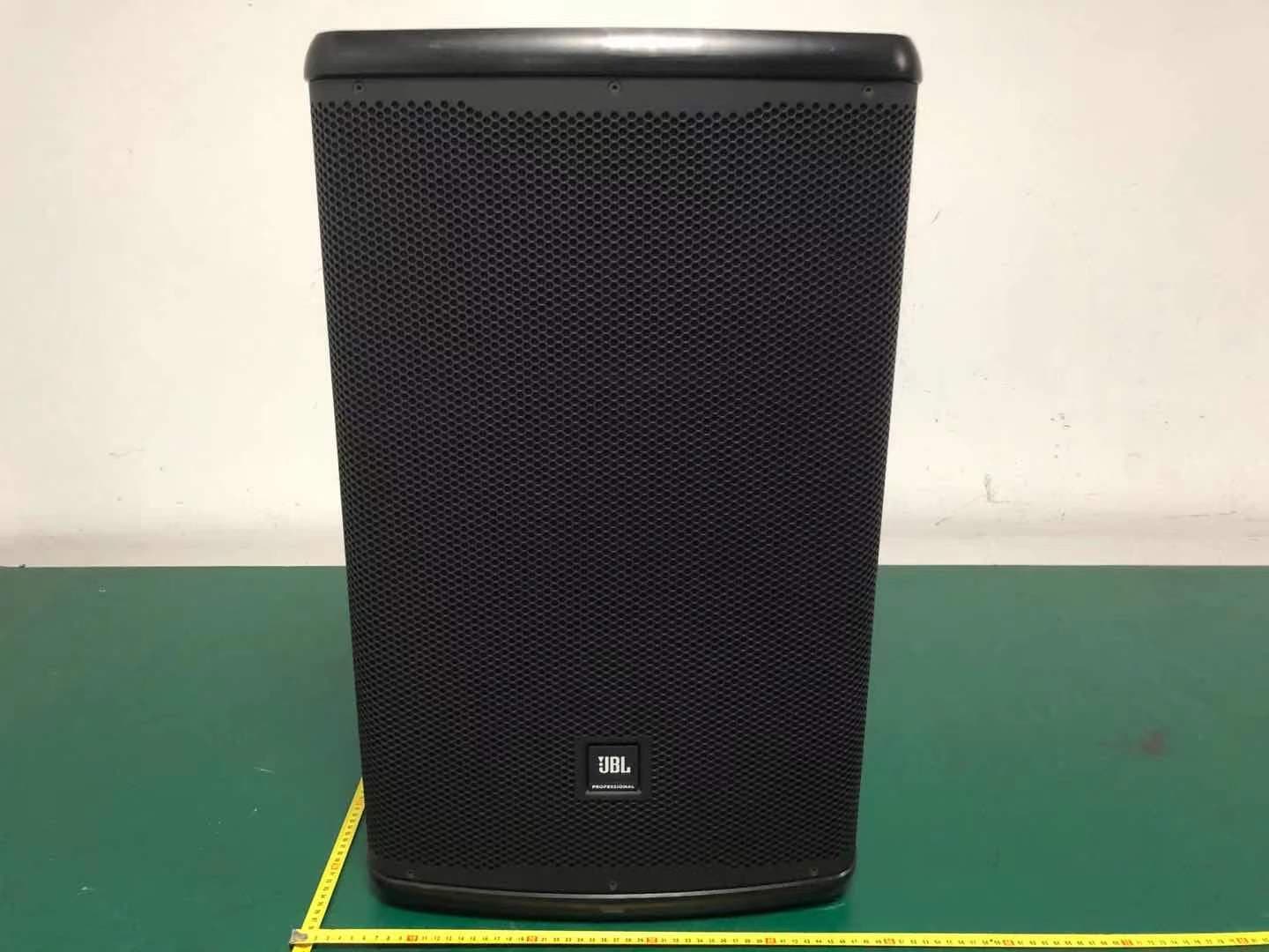
2AUHEEON700
Apr 12, 2021POWERED SPEAKER W/BLUETOOTH
Equipment Class
DTS - Digital Transmission System