2AUI4-OS-M385C2Face Recognition Terminal
Universal Ubiquitous AI Co., Ltd.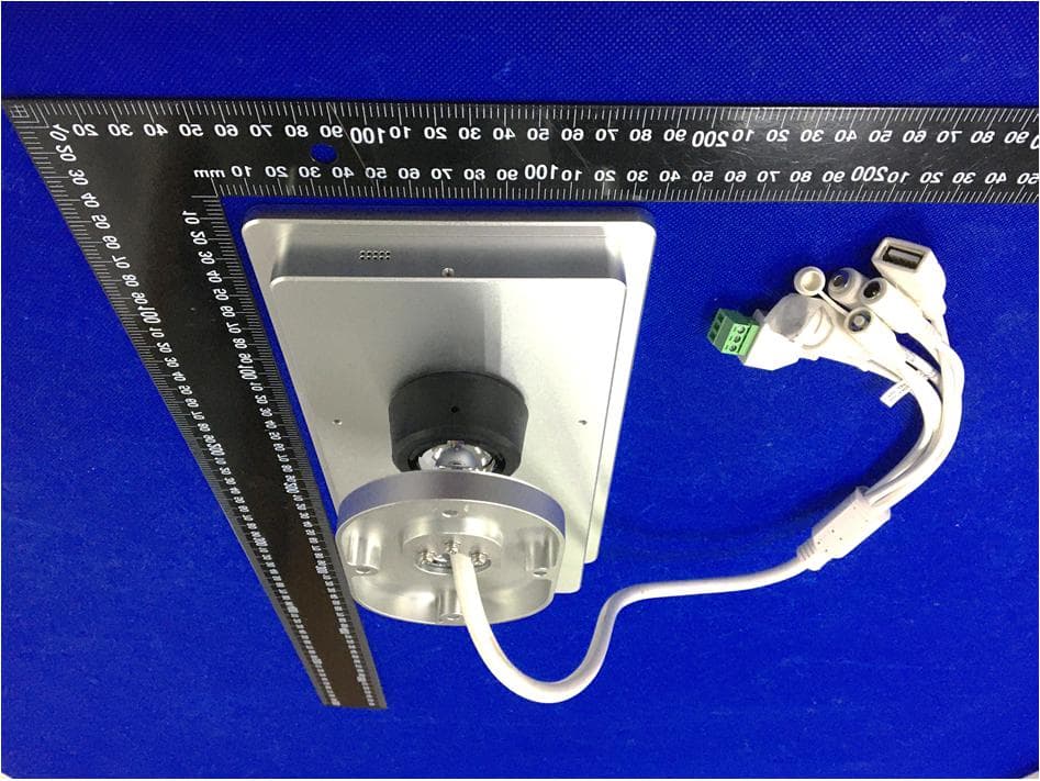
Click to zoom
Application Details
- Equipment Class
- DXX - Part 15 Low Power Communication Device Transmitter
- Date of Grant
- Feb 22, 2021
- Application Purpose
- Original Equipment
- Date of Application
- Feb 22, 2021
- Equipment Note
- Face Recognition Terminal
- Frequency Range
- 13.56000000 - 13.56000000
- Country
- China
Documents & Files
Document Text
Text extracted from the exhibit documents filed with the FCC. Open a document above to read the original.
Users Manual
PRODUCT BOOKLET Uface 8T-Temp ( OS-M385C2-C-R23WFC-TEMP03 ) Device introduction Parts list Dimensional drawing Platform/Software operating instruction Appearance description Illumination intensity Position Height Steps Wiring connection Features FAQ Installation Product description No. QuantityName 11Host 21Power adapter 31User manual 4 5 1 1Hexagonal wrench 613*12 Self-tapping screw 71Ziplock plastic bag - transparent Parts list Dimensional drawing Dear customer: Thank you for using our product. For better use, please carefully read this instruction. If you have any issues not mentioned here, please contact the provider. All parts of this booklet are reserved by our company, including words, pictures and graphics. Without written permission, no unit or individual shall extract, copy, translate or edit the content in this instruction. Unit: mm Appearance description Instruction 1 / 2 Infrared camera RGB camera Platform/Software Operating Instruction Thermometer sensor USB interface Audio interface Digital interface Reset buttonPowerNet mouth Wiegand WD0 GND WD1 Wiegand 26&34 signal output. Wiegand signal 0 output end, 1 output end GND gound lead Please mark the need for software version when place the order. For more detailed platform/software The recognized face, of which, the illumination intensity (“intensity” in short) shall not be lower than 30 Lux when the device put in a totally dark environ- ment, the face illumination intensity, 0.5m distance to the device, is about 100 Lux. The nearer to the device, the higher the intensity is. If there is overexposure on the face, the face characteristics will be unable to be extracted and may lead to hard recognition. image and registered image; backlight, side-light and (Analysis: from the view of human eyes, the color changes on face skin may result in wrong recognition of identity; unclear exposure area, no matter large or The test standard is as shown on the picture: the angle between dotted line A and dotted line B is 90°, the test adopts the common light meter with full spectrum, and applies U30 stan- dard light source; adjust the distance between source light and test object, subject to the illumination intensity of the object’s face at this time. Back light Intensity test Illumination intensity in actual scenarios Strong light Side light Light source is near the object Device stands between the light source and object Object stands between the device and light source Side-light may lead to uneven light on the face Backlight may make the face too dark Direct strong light may cause overexposure 500Lux, overexposure 30 Lux, dim 100 Lux, bright 50 Lux, normal 300 Lux, slight exposure Reference to intensity Illumination intensity 1. Install the device in a place with little impact from light source. 2. Add a registered image according to the site condition, and it is suggested to use this product to enroll images. 3. Properly lower the threshold value according to usage. Improvements Device 0.5m~1m d 90° Test object Light source A B When the sunlight shines indoor through the window, the face recognition terminal device shall not be installed in shown black shadow area, instead, shall be installed in place with little sunlight impact, no side-light and no backlight. (Glass window can be deemed as no walls) Sunlight shines indoor If the room has glass wall, there is no shield for sunlight, then it is suggested to hang curtains over the window, and install the the recognition. (Glass window can be deemed as no walls) Glass window Sunlight shines through the door, the device shall be installed at the place with shields and little light impact. Glass window can be deemed as no shields, the device shall be installed at the side without glass window or with curtain hung. Sunlight shines through the door, with glass window at one side Sunlight shines through the door, the device shall be installed at the place with shields and little light impact. Sunlight shines through the door Suggested installation height (the distance between the lens and the ground) is 1.4m, as the recognizable body height range, 0.5m distance away from the device, is 1.3m-1.7m; the recognizable body height range, 1m distance away from the device, is 1m-2m. (There are some deviations) Camera vertical wide-angleCamera horizontal wide-angle Position 3 / 4 Height Glass window (same as the semi-outdoor scene with no walls) DeviceLight DoorWall Person Curtain Device shall be installed in places avoiding backlight, side-light and strong light. This place, 3m away from the window, or does not Backlight, side-light or direct strong light, not suitable for installation. Other areas, install in suitable places according to actual light impact. Indoor Door Light Wall/Shields Indoor Door Light Wall/Shields Indoor LightDoor Door Wall/Shields Indoor Door Wall/Shields Light Glass wall FOV(H) FOV(H) User Recognition area Device Gate Steps 5 / 6 According to the site requirements, drill a 32mm-diameter hole in the gate (commonly in the middle or the front), as shown on the picture, is the suggested hole position. Single-channel gateDual-channel gate 50CM Attention: Hole position should be decided by actual scenes and applied gate type, 50cm is the reference value only. 1 2 4 3 Attention: a) At this time, do not connect cables such as network cable and power cable, to avoid the trouble of installation. b) Please thread the 4 cables out one by one, instead of threading all 4 cables together, as shown on the picture. Insert the column and cables into the hole on the gate, from top to bottom. Connect power and network cable, boot the device and display screen. Adjust the support angle to reach the optimal recognition angle as well as optimal recognition height range. Take down the nut Tighten the nut Inner hexagon screw Inner hexagon screw Plastic nut Use hexagon screw tool or hexagon screw driver to loosen the screw, adjust the angle and then tighten 7 / 8 Wiring for automatic doorInstallation…
Text truncated - open the document above for the full version.
External Photos
Reference No.: WTX20X12098109W-1/2 Page 2 of 15 Waltek Testing Group (Shenzhen) Co., Ltd. http://www.semtest.com.cn EXHIBIT 2 - EUT EXTERNAL PHOTOGRAPHS EUT View 1 EUT View 2 Reference No.: WTX20X12098109W-1/2 Page 3 of 15 Waltek Testing Group (Shenzhen) Co., Ltd. http://www.semtest.com.cn EUT View 3 EUT View 4 Reference No.: WTX20X12098109W-1/2 Page 4 of 15 Waltek Testing Group (Shenzhen) Co., Ltd. http://www.semtest.com.cn EUT View 5 EUT View 6 Reference No.: WTX20X12098109W-1/2 Page 5 of 15 Waltek Testing Group (Shenzhen) Co., Ltd. http://www.semtest.com.cn EUT View 7
ID Label/Location Info
Reference No.: WTX20X12098109W-1/2 Page 1 of 15 Waltek Testing Group (Shenzhen) Co., Ltd. http://www.semtest.com.cn ANNEX EXHIBIT 1 - PRODUCT LABELING Proposed FCC ID Label Format FCC ID: 2AUI4-OS-M385C2 Specifications: The label shall be securely affixed to a permanently attached part of the device, in a location where it is visible or easily accessible to the user, and shall not be readily detachable. The label shall be sufficiently durable to remain fully legible and intact on the device in all normal conditions of use throughout the device’s expected lifetime. Proposed Label Location on EUT FCC ID Label Location
Internal Photos
Reference No.: WTX20X12098109W-1/2 Page 6 of 15 Waltek Testing Group (Shenzhen) Co., Ltd. http://www.semtest.com.cn EXHIBIT 3 - EUT INTERNAL PHOTOGRAPHS EUT Housing and Board View 1 Solder Board-Component View 1 Reference No.: WTX20X12098109W-1/2 Page 7 of 15 Waltek Testing Group (Shenzhen) Co., Ltd. http://www.semtest.com.cn Solder Board-Component View 2 Solder Board-Component View 3 Reference No.: WTX20X12098109W-1/2 Page 8 of 15 Waltek Testing Group (Shenzhen) Co., Ltd. http://www.semtest.com.cn Solder Board-Component View 4 Solder Board-Component View 5 Reference No.: WTX20X12098109W-1/2 Page 9 of 15 Waltek Testing Group (Shenzhen) Co., Ltd. http://www.semtest.com.cn Solder Board-Component View 6 Solder Board-Component View 7 Reference No.: WTX20X12098109W-1/2 Page 10 of 15 Waltek Testing Group (Shenzhen) Co., Ltd. http://www.semtest.com.cn Solder Board-Component View 8 Solder Board-Component View 9 Reference No.: WTX20X12098109W-1/2 Page 11 of 15 Waltek Testing Group (Shenzhen) Co., Ltd. http://www.semtest.com.cn Solder Board-Component View 10 Antenna View Reference No.: WTX20X12098109W-1/2 Page 12 of 15 Waltek Testing Group (Shenzhen) Co., Ltd. http://www.semtest.com.cn Antenna View
Test Report
Waltek Testing Group (Shenzhen) Co., Ltd. http://www.semtest.com.cn Page 1 of 24 TEST REPORT Reference No. .................... : WTX20X12098109W-2 FCC ID ................................ : 2AUI4-OS-M385C2 Applicant ........................... : Universal Ubiquitous Co., Ltd. Address.............................. : Room 658, Building 1, No.1, Lvting Road, Cangqian Street, Yuhang District, Hangzhou City Product Name ................... : Face Recognition Terminal Test Model. ........................ : OS-M385C2-V-R23WFC-TEMP03 Standards .......................... : FCC Part 15.225 Date of Receipt sample .... : Dec.16, 2020 Date of Test........................ : Dec.16, 2020 to Dec.18, 2020 Date of Issue ..................... : Dec.18, 2020 Test Result ......................... : Pass Remarks: The results shown in this test report refer only to the sample(s) tested, this test report cannot be reproduced, except in full, without prior written permission of the company. The report would be invalid without specific stamp of test institute and the signatures of compiler and approver. Prepared By: Waltek Testing Group (Shenzhen) Co., Ltd. Address: 1/F., Room 101, Building 1, Hongwei Industrial Park, Liuxian 2nd Road, Block 70 Bao'an District, Shenzhen, Guangdong, China Tel.: +86-755-33663308 Fax.: +86-755-33663309 Tested by: Reviewed By: Approved & Authorized By: Mike Shi / Project Engineer Lion Cai / RF Manager Silin Chen / Manager Reference No.: WTX20X12098109W-2 Page 2 of 24 Waltek Testing Group (Shenzhen) Co., Ltd. http://www.semtest.com.cn TABLE OF CONTENTS 1. GENERAL INFORMATION ...................................................................................................................................4 1.1 PRODUCT DESCRIPTION FOR EQUIPMENT UNDER TEST (EUT) ...............................................................................4 1.2 TEST STANDARDS ...................................................................................................................................................5 1.3 TEST METHODOLOGY .............................................................................................................................................5 1.4 TEST FACILITY .......................................................................................................................................................5 1.5 EUT SETUP AND TEST MODE .................................................................................................................................6 1.6 MEASUREMENT UNCERTAINTY ..............................................................................................................................6 1.7 TEST EQUIPMENT LIST AND DETAILS .....................................................................................................................7 2. SUMMARY OF TEST RESULTS ...........................................................................................................................8 3. ANTENNA REQUIREMENT ..................................................................................................................................9 3.1 STANDARD APPLICABLE .........................................................................................................................................9 3.2 TEST RESULT..........................................................................................................................................................9 4. RADIATED EMISSIONS ....................................................................................................................................... 10 4.1 STANDARD APPLICABLE ....................................................................................................................................... 10 4.2 TEST PROCEDURE ................................................................................................................................................. 10 4.3 CORRECTED AMPLITUDE & MARGIN CALCULATION ............................................................................................ 12 4.4 SUMMARY OF TEST RESULTS/PLOTS .................................................................................................................... 13 5. OUT OF BAND EMISSIONS ................................................................................................................................. 16 5.1 STANDARD APPLICABLE ....................................................................................................................................... 16 5.2 TEST PROCEDURE ................................................................................................................................................. 16 5.3 SUMMARY OF TEST RESULTS/PLOTS .................................................................................................................... 16 6. FREQUENCY STABILITY ................................................................................................................................... 18 6.1 STANDARD APPLICABLE ....................................................................................................................................... 18 6.2 TEST PROCEDURE ................................................................................................................................................. 18 6.3 SUMMARY OF TEST RESULTS/PLOTS .................................................................................................................... 18 7. EMISSION BANDWIDTH ..................................................................................................................................... 19 7.1 APPLICABLE STANDARD ....................................................................................................................................... 19 7.2 TEST PROCEDURE ..................................................................................................…
Text truncated - open the document above for the full version.
Test Setup Photos
Reference No.: WTX20X12098109W-1/2 Page 13 of 15 Waltek Testing Group (Shenzhen) Co., Ltd. http://www.semtest.com.cn EXHIBIT 4 - TEST SETUP PHOTOGRAPHS Conducted Emission Test Setup Radiation Emission Test Setup (Below 30MHz) Reference No.: WTX20X12098109W-1/2 Page 14 of 15 Waltek Testing Group (Shenzhen) Co., Ltd. http://www.semtest.com.cn Radiation Emission Test Setup (30MHz to 1GHz) Radiation Emission Test Setup (1GHz to 18GHz) Reference No.: WTX20X12098109W-1/2 Page 15 of 15 Waltek Testing Group (Shenzhen) Co., Ltd. http://www.semtest.com.cn Radiation Emission Test Setup (Above 18GHz) ***** END OF REPORT *****
Contact Information
Applicant
Fangfang Liu(engineer)
Test Firm
Waltek Testing Group (Shenzhen) Co., Ltd.Jandy So
Technical Specifications
| # | Rule Parts | Frequency Range | Power Output |
|---|---|---|---|
| 1 | 15C | 13.56 MHz - 13.56 MHz | - |
Other Applications from Universal Ubiquitous AI Co., Ltd.
2AUI4-UFACE87
Sep 11, 2026Face Recognition Terminal
Equipment Class
DCD - Part 15 Low Power Transmitter Below 1705 kHz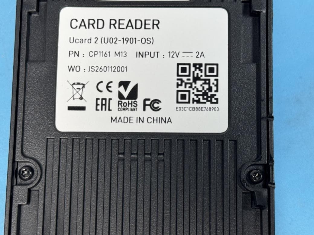
2AUI4-UCARD2
Apr 09, 2026CARD READER
Equipment Class
DCD - Part 15 Low Power Transmitter Below 1705 kHz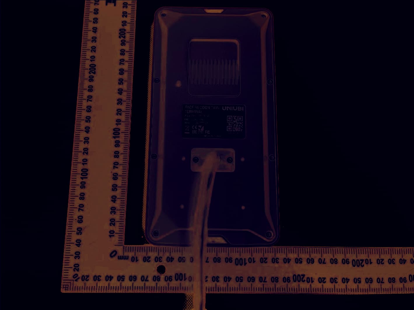
2AUI4-E73
Jan 11, 2024FACE RECOGNITION TERMINAL
Equipment Class
DSS - Part 15 Spread Spectrum Transmitter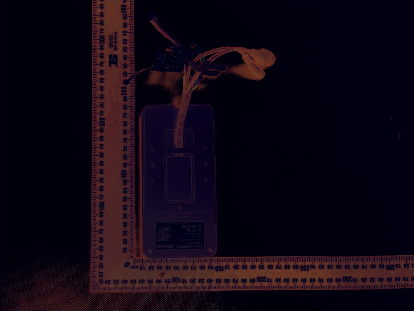
2AUI4-E53
Jan 10, 2024FACE RECOGNITION TERMINAL
Equipment Class
DXX - Part 15 Low Power Communication Device Transmitter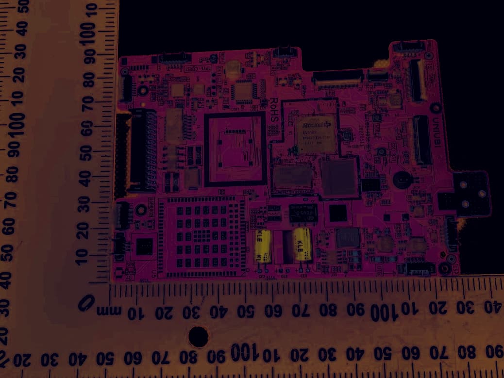
2AUI4-E86
Jan 10, 2024FACE RECOGNITION TERMINAL
Equipment Class
DTS - Digital Transmission System