2AUISION4Dual band 2X2 Outdoor Access Point (AP) with integrated antenna
HFCL Limited
Click to zoom
Application Details
- Equipment Class
- DTS - Digital Transmission System
- Date of Grant
- Mar 17, 2020
- Application Purpose
- Original Equipment
- Date of Application
- Mar 17, 2020
- Equipment Note
- Dual band 2X2 Outdoor Access Point (AP) with integrated antenna
- Frequency Range
- 2422.00000000 - 2452.00000000
- Company
- HFCL Limited
- Country
- India
Documents & Files
Document Text
Text extracted from the exhibit documents filed with the FCC. Open a document above to read the original.
Users Manual
Revision: A0-00 08 th Jan 2020 This document helps you to understand the product feature s , configura t io n, login and logout process of Thin and Thic k Access Point. This manua l guides you through the installa t io n process and the entire software user set. 2x2 Indoor & Outdoor Access Points Revision: A0-00 2 CONFIDENTIA L Copyright Notice This document is copyright of HFCL Limit e d, All Rights Reserved. No part of this document, in whole or in part, may be used, reproduced, stored in a retrieval system or transmitted, in any form, or by any means, electronic or otherwise, including photocopying, reprinting, or recording, for any purpose, without the express written permission of HFCL Limit e d. Legal Disclaimer The information contained in this document is subject to change without notice. The information in this document is provided for informational purposes only. HFCL Limit e d specifically d is claims all warran t ies , exp res s o r limit e d , including, but not limited, to the implied warranties of merchantability and fitness for a particular purpose, except as provided for in a separate software license agreement. About HFCL Limit e d HFCL Limit ed delivers innovative, customized and competitive products and latest solutions in the high technology telecommunications infrastructure sector, thereby enabling its customers to stay ahead of their peers in technology and network efficiency. The company’s core specialization lies in manufacturing and providing a wide range of turnkey solutions. HF CL Limit ed has implemented several Greenfield projects (setting up CDMA & GSM networks, satellite communications, wireless spectrum management and DWDM optical transmission network), rolled out over 100,000 kilometres of OFC network, implemented over 25,000 2G/3G cell sites, provided high security applications to Defence and has developed expertise in the areas of Railways, Homeland Security and Smart cities. Correspondence HFCL Limit ed 8, Commercial Complex, Masjid Moth, Greater Kailash II, New Delhi-11004 8, In d ia Co n tact u s at: +91 11308826 2 4/2 62 6 For your queries please mail us at: Sales: [email protected] Enquiry: [email protected] Investors: [email protected] 2x2 Indoor & Outdoor Access Points Revision: A0-00 3 CONFIDENTIA L Revision History Date Rev No. De s cription By 08-01-2020 A0-00 I nitia l D r a f t Himankush 2x2 Indoor & Outdoor Access Points Revision: A0-00 4 CONFIDENTIA L Table of Contents 1 ABOUT THIS DOCUMENT .......................................................................................................... 11 1.1 P URPOSE............................................................................................................................ 11 1.2 I NTENDED AU D IEN CE ............................................................................................................ 11 1.3 DOCUMENT CONVENTIONS..................................................................................................... 11 1.4 TERMS AND ABBREVIATIONS................................................................................................... 12 2 PRODUCT OVERVIEW ............................................................................................................... 15 3 FEDERAL COMMUNICATION COMMISSION CERTIFIED............................................................... 15 3.1 D UAL BAND 2X2:2 INDOOR ACCES S POI NT.................................................................................. 16 3.2 DUAL BAND 2X2:2 OU T D O OR ACCESS POI N T (I ON4/I ON4E)............................................................ 18 4 HARDWARE SETUP ................................................................................................................... 20 4.1 S YSTEM REQUI REMENTS ......................................................................................................... 20 4.2 PACKAGING CONTENT – FOR I ON4I/I ON4/I ON4E VARIANTS OF THIS PR ODUCT ...................................... 21 5 GETTING TO KNOW THE IO ACCESS POINT ................................................................................ 22 5.1 DUAL BAND 2X2:2 INDOOR ACCES S POI NT.................................................................................. 22 5.1.1 Back / Side View ........................................................................................................... 22 5.2 DUAL BAND 2X2:2 OU T D O OR ACCESS POI N T............................................................................... 24 5.2.1 Front / Side View .......................................................................................................... 24 5.3 BACK VIEW ......................................................................................................................... 25 6 INITIAL SETUP .......................................................................................................................... 27 6.1 D UAL BAND 2X2:2 INDOOR ACCES S POI NT.................................................................................. 28 6.1.1 Connect to the Indoor Access Point ................................................................................ 29 6.2 DUAL BAND 2X2:2 OU T D O OR ACCESS POI N T............................................................................... 30 6.2.1 Connect to the Outdoor Access Point ............................................................................. 31 7 CONNECT TO THE THIN MODE ACCESS POINT AND LOG IN ........................................................ 32 7.1 L OG IN THR OUG H GUI ............................................................................................................ 32 8 STATUS OVERVIEW SCREEN...................................................................................................... 33 8.1 S YSTEM SUMMARY................................................................................................................ 33 8.2 SYSTEM SOFTW A R E .................…
Text truncated - open the document above for the full version.
Users Manual
2x2 Indoor & Outdoor Access Points Revision: A0-00 47 CONFIDENTIA L Callout N a me De s cription 5. Model Displays the model number of the product. The same is configured with the factory settings of the device and reflects in this section on system boot up 6. Product Name Displays the name of the product 7. Current Mode Displays the current acting mode of the AP (Thick mode or Thin mode) 8. Current Partition Displays the current partition in use 9. Lo cal Time Displays the date and time details according to the time zone allocated in the “System Configuration” screen 10. System uptime Displays the time duration since the respective AP board is up and successfully running without any shutdown 11. Average Load Displays the average load on the device 12. M e mo ry Displays the free and available memory of the respective device 13. Network/IPv4 Address Displays the IPv4 address of the respective device 14. Network/IPv6 Address Displays the IPv6 address of the respective device 14.2 System software A basic layout of the system software is given below: Figure 26: Basic layout of the system software screen Follow the steps given below to view the system software information: Table 18: List of information displayed in the system software screen Callout N a me De s cription 1. Status Click on the “Status” dropdown 2. Overview Click on “Overview” option 3. Software Click on “Software” option 4. Firmware Vers ion Displays the current and alternate firmware vers ion of the respective AP. The operating system is based on openwrt project model 2x2 Indoor & Outdoor Access Points Revision: A0-00 48 CONFIDENTIA L 14.3 System hardware A basic layout of the system hardware is given below: Figure 27: Basic layout of the system hardware screen Follow the steps given below to view the system hardware information: Table 19: List of information displayed in the system hardware screen Callout N a me De s cription 1. Status Click on the “Status” dropdown 2. Overview Click on “Overview” option 3. Hardware Click on “Hardware” option 4. Hardware Version Displays the current hardware version of the respective AP 5. Device Type Displays the device type (Indoor or Outdoor) 6. Serial Number Displays the serial number of the respective AP. The same is configured with the factory settings of the device and reflects in this section on system boot up 7. MAC-Address Displays the MAC address assigned to the product. The same is configured with the factory settings of the device and reflects in this section on system boot up 2x2 Indoor & Outdoor Access Points Revision: A0-00 49 CONFIDENTIA L 14.4 S ys te m wire le s s A basic layout of the thick AP system wireless overview is given below: Figure 28: Basic layout of the thick AP system wireless ov erv iew screen Follow the steps given below to view thick AP system wireless overview: Table 20: List of information displayed in thick AP system wireless ov erv iew Callout N a me De s cription 1. Status Click on the “Status” dropdown 2. Overview Click o n “Overview” option 3. W ireles s Click o n “W ireles s ” o p t io n 4. Radio 5 GHz Displays the current radio operating mode of the access point at 5 GHz. Refer the section for 5 GHz radio configurations 5. SSID 5 GHz Displays all configured SSIDs operating at 5 GHz in a lis t ed form along with some basic details as shown in the figure above. Refer the section for configuration of SSIDs operating at 5 GHz radio 6. Rad io 2.4 GHz Displays the current radio operating mode of the access point at 2.4 GHz. Refer the section for 2.4 GHz rad io configurations 7. SSID 2.4 GHz Displays all configured SSIDs operating at 2.4 GHz in a listed form along with some basic details as shown in the figure above. Refer the section for configuration of SSIDs operating at 2.4 GHz radio 2x2 Indoor & Outdoor Access Points Revision: A0-00 50 CONFIDENTIA L 15 System maintenance screen The maintenance activities of the respective access point are executed from this screen. The list of options available for the user is given below: 1. System general and log settings 2. Admin password configuration 3. Backup/Flash Firmware 4. Reboot 5. Factory Reset 15.1 System general settings The user can configure the basic aspects of the respective access point, like its hostname and the timezone. A basic overview of the screen is given below: Figure 29: Basic overview of the system general settings screen for thick AP Follow the steps given below and configure the system general settings for the thick AP: Table 21: List of actions to configure the system general settings for thick AP Callout N a me De s cription 1. Sys tem Click on “System” dropdown 2. Sys tem Click on “System” option 3. General Settings Click on “General Settings” option 4. Lo cal Time Displays the local date and time of the region. The user can click on “Sync with browser” option to sync the date and time 5. Hos t Name Enter the “Hostname”. The same will be reflected in the system summary of status overview screen 6. Time Zone Select the respective “Timezone” from the dropdown list. It represents the region of the globe that observes a uniform standard time for legal, commercial, and social purposes. 2x2 Indoor & Outdoor Access Points Revision: A0-00 51 CONFIDENTIA L Callout N a me De s cription The date and time of the respective timezone will be reflected in the system summary of status overview screen. 7. Time sync/ NTP Click on the check box and enable or disable the NTP client 8. NTP Server candidates Click on the + icon and add multiple servers Click on “Save & Apply” to save the system admin password configuration or click “Reset” to configure the same again. 2x2 Indoor & Outdoor Access Points Revision: A0-00 52 CONFIDENTIA L 15.2 System log settings If user wants to see the back-end logs or if user faces any issue, logs relevant to the AP’s application software are populated in the Diagnostic/ System LogError! Reference source not found. screen for monitoring purpose. The same can be uploaded t…
Text truncated - open the document above for the full version.
Users Manual
2x2 Indoor & Outdoor Access Points Revision: A0-00 80 CONFIDENTIA L 16.4 DHC P and DN S configura t io n of thick AP The AP itself can act as a DHCP service provider for the connected clients and configuration for the same is executed from this screen. A basic overview of the screen to enable thick AP as DHCP server is given below: Figure 53: Basic ov erv iew of the screen to enable thick AP as DHCP serv er Follow the steps given below to enable thick AP as DHCP server: Table 43: List of actions to enable thick AP as DHCP serv er Callout N a me De s cription 1. Network Click o n “Network” dropdown 2. DHCP and DNS Click on “DHCP and DNS” option 3. DHCP Server Enable the thick AP as DHCP server and enter the following parameters 4. IPv4 Address Enter the address in IPv4 format for the DHCP server 5. IPv4 Netmask Select the netmask from the dropdown list 6. IPv4 Gateway Enter the address in IPv4 format for the DHCP gateway 7. Us e Cus tom DNS Servers Enter the IP address for DNS server. Click on add icon and mu lt ip le DNS s erv ers 8. Start IP Addres s Enter a start IP address. The DHCP server assigns the new IP addresses to the clients from the defined start IP address 9. End IP Address Enter an end IP address. The DHCP server assigns the IP addresses to the clients till the defined end IP address 10. Lease Time Enter a value to set a limit on the lease time. New addresses will be assigned to the associated clients once the previous lease has expired as per the specified lease time Click “Save & Apply” to enable thick AP as DHCP server or click “Reset” to configure the same again. 2x2 Indoor & Outdoor Access Points Revision: A0-00 81 CONFIDENTIA L 16.4.1 S tatic/Active lease settings Static leases are used to assign fixed IP addresses and symbolic hostnames to DHCP clients. They are also required for non-dynamic interface configurations where only hosts with a corresponding lease are served. A basic overview of the screen to configure a static lease is given below: Figure 54: Basic overview of the screen to configure a static lease Follow the steps given below to configure a static lease: Table 44: List of actions to configure a static lease Callout N a me De s cription 1. Network Click on “Network” dropdown 2. DHCP and DNS Click on “DHCP and DNS” option 3. Add Click on “Add” option to add a new static lease. The user can add multiple static leases 4. Hos t Name Provide a unique name to the static lease for identification 5. MAC-Address Click on the dropdown and select a MAC-address from the list. The selected MAC-address identifies the host 6. IPv4 Address Click on the dropdown and select an IPv4-address from the lis t . Th e selected IPv4-address is assigned to the host as a fixed address 7. IPv6-Suffix Enter the IPv6-suffix for the host Click “Save & Apply” to save the static lease or click “Reset” to configure the same again. 8. Delete Click on the “Delete” option to remove the respective static lease 9. Active DHCP Leases Dis p lay s all active IPv4 leases in a listed form 10. Active DHCPv6 Leases Displays all active IPv6 leases in a listed form 2x2 Indoor & Outdoor Access Points Revision: A0-00 82 CONFIDENTIA L 16.5 Static Routes User can configure static routes and redirect packets to the destination network. A static route is a pre-determined pathway that a packet must travel to reach a specific host or network. A basic overview of the static route configuration screen for thick AP is given below: Figure 55: Basic overview of the static route configuration screen for thick AP Follow the steps given below for static route configuration of thick AP: Table 45: List of actions for static route configuration of thick AP Callout N a me De s cription 1. Network Click on “Network” dropdown 2. Static Route Click on “Static Route” option Static IPv4 Routes 3. Add Click on “Add” option to add a new static route in IPv4 format 4. Interface Select the physical network interface through which this route is accessible from the dropdown list (WAN or LAN) 5. Target Enter the IP address of the destination host or network in IPv4 format to which the route leads. 6. IPv4-Netmask Enter the IPv4 netmas k for the destination host or network. By default subnet mask is set to 255.255.255.255 7. IPv4-Gateway Enter the IP address of the gateway in IPv4 format through which the destination host or network can be reached. If the current AP is being us ed to connect network with the Internet, then your gateway IP is the AP's IP address. If you 2x2 Indoor & Outdoor Access Points Revision: A0-00 83 CONFIDENTIA L Callout N a me De s cription have another router handling your network's Internet connection, enter the IP address of that router instead 8. M et ric Enter a value that defines the priority of the route. If multiple routes to the same destination exist, the route with the lowest metric is chosen 9. MTU Enter the MTU size, by default it is set to 1500. Click “Save & Apply” to save the static IPv 4 route configuration or click “Reset” to configure the same again. Static IPv6 Routes 10. Add Click on “Add” option to add a new static route in IPv6 format 11. Interface Select the physical network interface through which this route is accessible from the dropdown list (WAN or LAN) 12. Target Enter the IP address of the destination host or network in IPv6 format to which the route leads. 13. IPv6-Gateway Enter the IP address of the gateway in IPv6 format through which the destination host or network can be reached. If the current AP is being used to connect network with the Internet, then your gateway IP is the AP's IP address. If you have another router handling your network's Internet connection, enter the IP address of that router instead 14. M et ric Enter a value that defines the priority of the route. If multiple routes to the same destination exist, the route with the lowest metric is chosen 15. MTU Enter the MTU size, by default it is set to 1500. Click “Save & Apply” to save the static IPv6 route confi…
Text truncated - open the document above for the full version.
Users Manual
2x2 Indoor & Outdoor Access Points Revision: A0-00 101 CONFIDENTIA L 2. Pass the U-bolt through the cuts of pole holder and mounting bracket. Tighten it in place with attaching nuts. Figure 74: Final alignment of 2x2 outdoor AP and mounting bracket 3. As shown above, the 2x2 outdoor AP has the freedom of movement along the vertical and horizontal axis. 2x2 Indoor & Outdoor Access Points Revision: A0-00 102 CONFIDENTIA L 4. The final alignment of 2x2 outdoor AP in a pole mounting is shown in the figure below: Figure 75: Basic overview of pole mounted 2x2 outdoor AP 2x2 Indoor & Outdoor Access Points Revision: A0-00 103 CONFIDENTIA L 21.2.2 2x2 outdoor AP mounting to the Wall To mount the device onto the wall, foundation bolts and attaching bolts are needed along with the wall mounting bracket. Refer the image given below: Figure 76: Items needed for wall mounting of the dev ice Follow the steps given below and mount the device onto the wall: 1. Take the reference from the printed sheet provided along with the wall mounting bracket and mark the position of the holes on the wall. 2. Use the drill machine to drill 2 holes with a 6mm drill tool on respective marked positions. 3. Push the foundation bolts into the holes with a hammer. 4. Align the drilled holes with the holes of wall mounting bracket. 5. Insert the attaching bolts through the holes of mounting bracket into the wall. 6. Wall mounting bracket is fixed to the wall. 7. Mount the device on to the wall mounting bracket as discussed in pole mounting process. 2x2 Indoor & Outdoor Access Points Revision: A0-00 104 CONFIDENTIA L Figure 77: Basic overview of wall mounted 2x2 outdoor AP 2x2 Indoor & Outdoor Access Points Revision: A0-00 105 CONFIDENTIA L 21.3 Grounding of AP The AP should be properly grounded upon installment. The IO’s 2x2 outdoor AP has a grounding position at the back side of the device as shown below: Figure 78: Grounding point of 2x2 outdoor AP A grounding strap can be made from the ring lug terminal of M4 size and a medium length copper wire of suggested gauge AWG-6 (4.1 mm). Insert the grounding wire and flush it till the end of the terminal. Use the crimp tool and reshape or compress the terminal. Use an M4x10 machine screw and attach the crimped lug with AP. 2x2 Indoor & Outdoor Access Points Revision: A0-00 106 CONFIDENTIA L 22 Use Cases A. Indoor Access Point Figure 79: Use Case Diagram of Indoor AP B. Outdoor Access Point Figure 80: Use Case Diagram of Outdoor AP
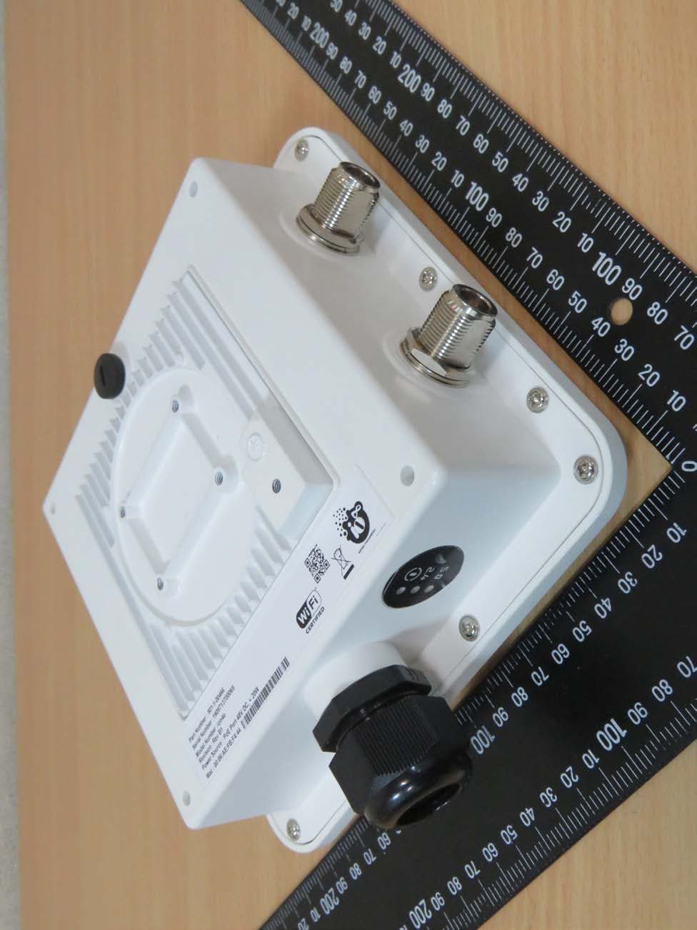
External Photos
Registration number: W6M22001-19621-FCC FCC ID: 2AUISION4 Worldwide Testing Services(Taiwan) Co., Ltd. Appendix page 2 of 15 External Photos Registration number: W6M22001-19621-FCC FCC ID: 2AUISION4 Worldwide Testing Services(Taiwan) Co., Ltd. Appendix page 3 of 15 Registration number: W6M22001-19621-FCC FCC ID: 2AUISION4 Worldwide Testing Services(Taiwan) Co., Ltd. Appendix page 4 of 15
Internal Photos
Registration number: W6M22001-19621-FCC FCC ID: 2AUISION4 Worldwide Testing Services(Taiwan) Co., Ltd. Appendix page 5 of 15 Internal Photos Registration number: W6M22001-19621-FCC FCC ID: 2AUISION4 Worldwide Testing Services(Taiwan) Co., Ltd. Appendix page 6 of 15 Registration number: W6M22001-19621-FCC FCC ID: 2AUISION4 Worldwide Testing Services(Taiwan) Co., Ltd. Appendix page 7 of 15 Registration number: W6M22001-19621-FCC FCC ID: 2AUISION4 Worldwide Testing Services(Taiwan) Co., Ltd. Appendix page 8 of 15 Registration number: W6M22001-19621-FCC FCC ID: 2AUISION4 Worldwide Testing Services(Taiwan) Co., Ltd. Appendix page 9 of 15 Registration number: W6M22001-19621-FCC FCC ID: 2AUISION4 Worldwide Testing Services(Taiwan) Co., Ltd. Appendix page 10 of 15 Registration number: W6M22001-19621-FCC FCC ID: 2AUISION4 Worldwide Testing Services(Taiwan) Co., Ltd. Appendix page 11 of 15 Registration number: W6M22001-19621-FCC FCC ID: 2AUISION4 Worldwide Testing Services(Taiwan) Co., Ltd. Appendix page 12 of 15 Registration number: W6M22001-19621-FCC FCC ID: 2AUISION4 Worldwide Testing Services(Taiwan) Co., Ltd. Appendix page 13 of 15
RF Exposure Info
Registration number: W6M22001-19621-C-1 FCC ID: 2AUISION4 3.2 Equivalent Isotropic Radiated Power (EIRP) FCC Rule: 15.247(b)(3) EIRP = max. conducted output power + antenna gain EIRP = 21.84 dBm+(11.01 dBi [antenna gain claimed by manufacturer]=32.85 dBm = 1927.5249 mW 3.3 Exemption Limits for Routine Evaluation according to 47 CFR FCC Part 2 Subpart J, section 2.1091 FCC OET Bulletin 65 Edition 97.01 determines the equations for predicting RF fields and applicable limits. The prediction for power density in the far-field but will over-predict power density in the near field, where it could be used for walking a “worst case” or conservative prediction. Systems operating under the provisions of this section shall be operated in a manner that ensures that the public is not exposed to radio frequency energy levels in excess limit for maximum permissible exposure. In accordance with 47 CFR FCC Part 2 Subpart J, section 2.1091 this device has been defined as a mobile device whereby a distance of 20 cm normally can be maintained between the user and the device. MPE Calculation Method Worldwide Testing Services(Taiwan) Co., Ltd. Page 28 of 70 Registration number: W6M22001-19621-C-1 FCC ID: 2AUISION4 E = Electric field (V/m) P = output power (W) G = EUT Antenna numeric gain (numeric) d = Separation distance between radiator and human body (m) The formula can be changed to mW/cm 2 . Established separation distance is 20 cm. Operating frequency band: 802.11b, g, n 20MHz: 2412-2462 MHz, 802.11n 40MHz: 2422-2452 MHz, The product meets RF exposure requirement. Because the power density of 0.3836 mW/cm 2 at 2462 MHz is below the power density limit of 1 mW/cm 2 . Limits: Limit for General Population / Uncontrolled Exposure Frequency (MHz) Power Density (mW/cm 2 ) 1500 – 100.000 1.0 Worldwide Testing Services(Taiwan) Co., Ltd. Page 29 of 70 Registration number: W6M22001-19621-C-54 FCC ID: 2AUISION4 3.6 Automatic Discontinuation of transmission, FCC 15.407 (c) The device shall automatically discontinue transmission in case of either absence of information to transmit or operational failure. This function will be declared by manufacturer. 3.7 Reserved, FCC 15.407 (d) 3.8 Indoor Operation Restriction, FCC 15.407 (e) Within the 5.15–5.25 GHz band, U- NII devices will be restricted to indoor operations to reduce any potential for harmful interference to co-channel MSS operations. This equipment has to be declared by manufacturer of the final product as content of the user manual. 3.9 Equivalent Isotropic Radiated Power (EIRP), FCC 15.407 (f) Band 1 EIRP = max. conducted output power + antenna gain EIRP = 19.55 dBm + (11.01 dBi [antenna gain claimed by manufacturer] = 30.56 dBm = 1137.6273 mW Band 4 EIRP = max. conducted output power + antenna gain EIRP = 19.38 dBm + (11.01 dBi [antenna gain claimed by manufacturer] = 30.39 dBm = 1093.9564 mW Test equipment used: ETSTW-RE 055 Worldwide Testing Services(Taiwan) Co., Ltd. Page 78 of 85 Registration number: W6M22001-19621-C-54 FCC ID: 2AUISION4 3.10 Exemption Limits for Routine Evaluation according to 47 CFR FCC Part 2 Subpart J, section 2.1091 FCC OET Bulletin 65 Edition 97.01 determines the equations for predicting RF fields and applicable limits. The prediction for power density in the far-field but will over-predict power density in the near field, where it could be used for walking a “worst case” or conservative prediction. Systems operating under the provisions of this section shall be operated in a manner that ensures that the public is not exposed to radio frequency energy levels in excess limit for maximum permissible exposure. In accordance with 47 CFR FCC Part 2 Subpart J, section 2.1091 this device has been defined as a mobile device whereby a distance of 20 cm normally can be maintained between the user and the device. E = Electric field (V/m) P = output power (W) G = EUT Antenna numeric gain (numeric) d = Separation distance between radiator and human body (m) The formula can be changed to mW/cm 2 . Worldwide Testing Services(Taiwan) Co., Ltd. Page 79 of 85 Registration number: W6M22001-19621-C-54 FCC ID: 2AUISION4 Band 1 Established separation distance is 20 cm. Operating frequency band: 5180-5240 MHz The product meets RF exposure requirement. Because the power density of 0.2264 mW/cm 2 at 5180 MHz is below the power density limit of 1 mW/cm 2 . Band 4 Established separation distance is 20 cm. Operating frequency band: 5745-5825 MHz The product meets RF exposure requirement. Because the power density of 0.2176 mW/cm 2 at 5795 MHz is below the power density limit of 1 mW/cm 2 . Limits: Limit for General Population / Uncontrolled Exposure Frequency (MHz) Power Density (mW/cm 2 ) 1500 – 100.000 1.0 Worldwide Testing Services(Taiwan) Co., Ltd. Page 80 of 85
Test Report
of Applicant: HFCL Limited Address: 8, Commercial Complex, Masjid Moth, Greater Kailash - 2, New Delhi-110048, India Tested and Prepared by Worldwide Testing Services (Taiwan) Co., Ltd. FCC Registration No.: TW1477, TW0020, TW1072 Industry Canada filed test laboratory Reg. No. 20037 A2LA Accredited No.: 2732.01 Report No.: W6M22001-19621-C-1 6F, NO. 58, LANE 188, RUEY-KUANG RD., NEIHU TAIPEI 114, TAIWAN, R.O.C. TEL: 886-2-66068877 FAX: 886-2-66068879 E-mail: [email protected] FCC PART 15 SUBPART C TEST REPORT for Dual band 2X2:2 Outdoor Access Point (AP) with integrated antenna Model No.: ion4 FCC ID: 2AUISION4 Registration number: W6M22001-19621-C-1 FCC ID: 2AUISION4 TABLE OF CONTENTS 1 GENERAL INFORMATION .......................................................................................................... 2 1.1 N OTES .......................................................................................................................................... 2 1.2 TESTING LABORATORY ................................................................................................................ 3 1.2.1 Location .............................................................................................................................. 3 1.2.2 Details of accreditation status ............................................................................................ 3 1.3 DETAILS OF APPROVAL HOLDER ................................................................................................... 3 1.4 APPLICATION DETAILS ................................................................................................................. 3 1.5 GENERAL INFORMATION OF TEST ITEM ........................................................................................ 4 1.6 T EST STANDARDS ......................................................................................................................... 6 2 TECHNICAL TEST ......................................................................................................................... 7 2.1 SUMMARY OF TEST RESULTS ........................................................................................................ 7 2.2 TEST ENVIRONMENT .................................................................................................................... 7 2.3 TEST EQUIPMENT LIST .................................................................................................................... 8 2.4 G ENERAL TEST PROCEDURE ...................................................................................................... 11 3 TEST RESULTS (ENCLOSURE) ................................................................................................ 13 3.1 PEAK OUTPUT POWER (TRANSMITTER) ...................................................................................... 14 3.2 EQUIVALENT ISOTROPIC RADIATED POWER ................................................................................ 28 3.3 RF EXPOSURE COMPLIANCE REQUIREMENTS ............................................................................ 28 3.4 TRANSMITTER RADIATED EMISSIONS IN RESTRICTED BANDS ...................…
Text truncated - open the document above for the full version.
Contact Information
Applicant
Bhuvnesh Sachdeva(Associate Vice President)
Technical Contact
Worldwide Testing Services (Taiwan) Co., Ltd.Danny Sung
[email protected]+886266068877
6F., No.58, Lane 188, Ruiguang Rd., Neihu District · Taipei · Taiwan
Test Firm
Worldwide Testing Services (Taiwan) Co., Ltd.Rex Kao
Technical Specifications
| # | Rule Parts | Frequency Range | Power Output |
|---|---|---|---|
| 2 | 15C | 2.42 GHz - 2.45 GHz | 78.30 mW |
Other Applications from HFCL Limited
2AUISION4E
Mar 18, 2020Dual band 2X2 Outdoor Access Point (AP) with external antenna
Equipment Class
NII - Unlicensed National Information Infrastructure TX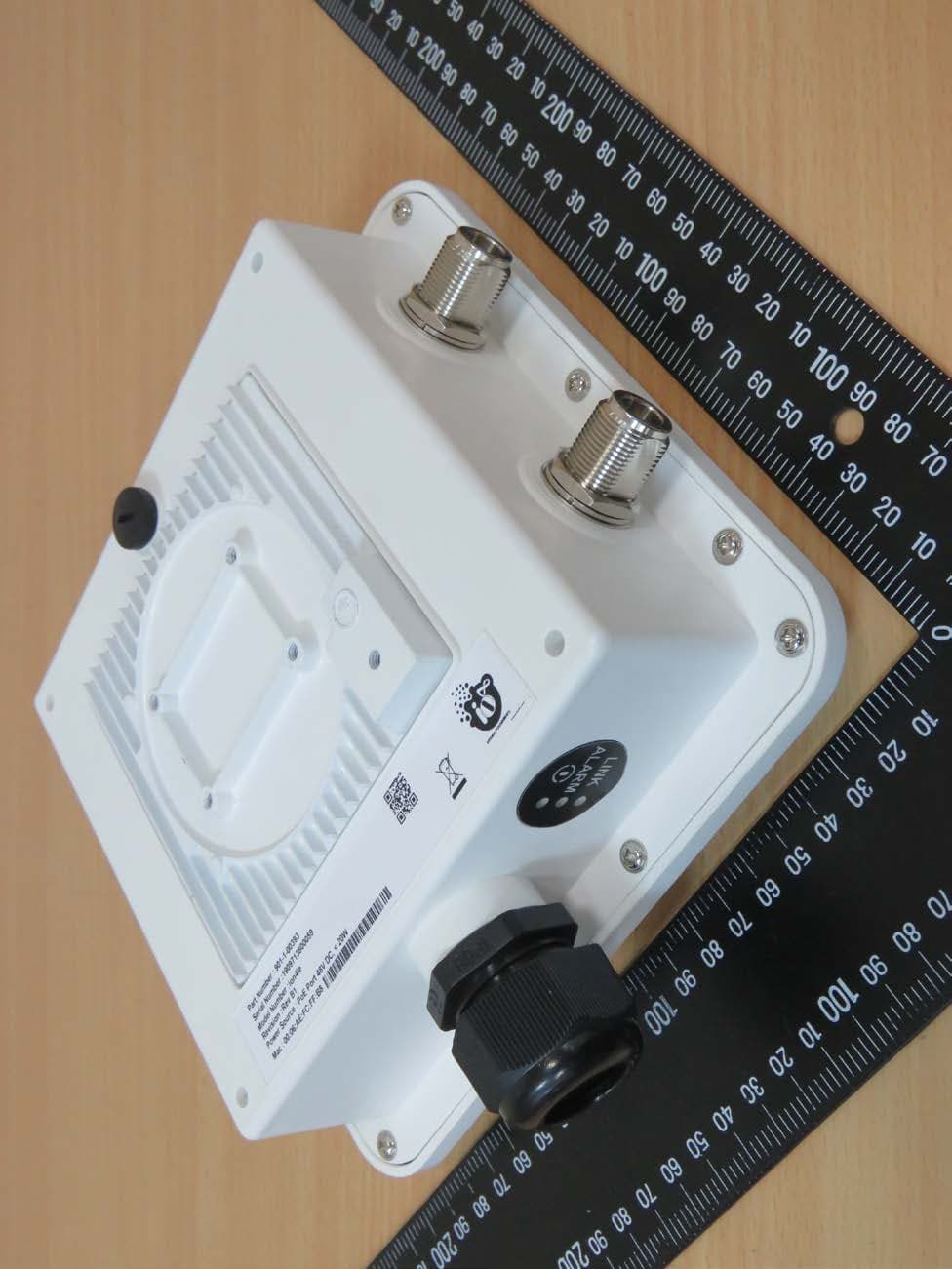
2AUISION4LE
Mar 17, 2020Unlicensed Band Radio (UBR) 2X2 with external antenna
Equipment Class
NII - Unlicensed National Information Infrastructure TX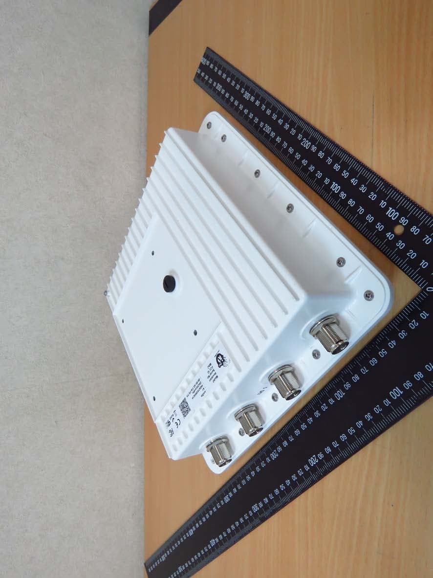
2AUISION8LE
Feb 27, 2020Unlicensed Band Radio (UBR) 4X4 with external antenna
Equipment Class
DTS - Digital Transmission System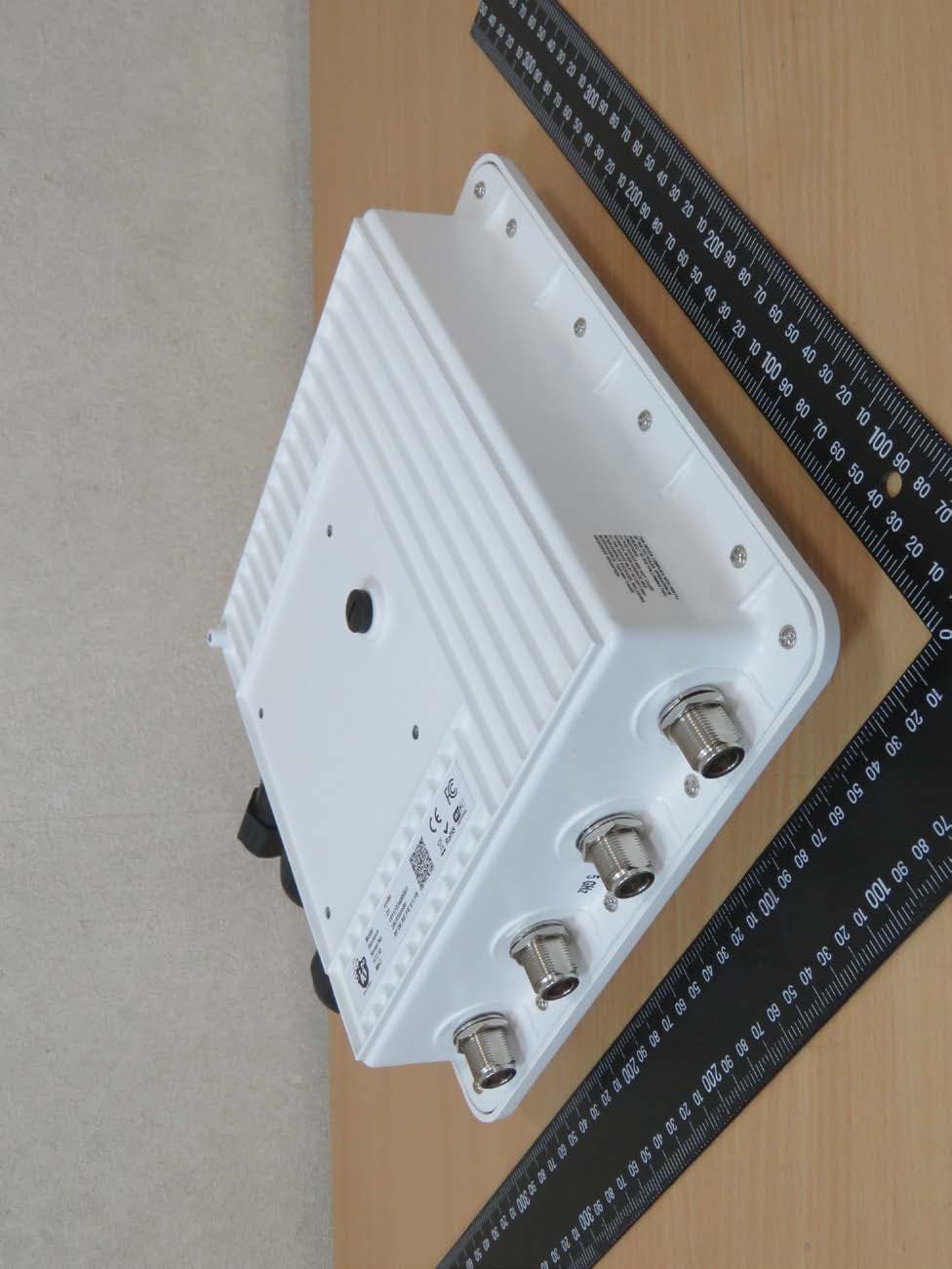
2AUISION8ION8E
Feb 04, 2020Dual band 4X4 0utdoor Access Point (AP) with integrated/external antenna
Equipment Class
NII - Unlicensed National Information Infrastructure TX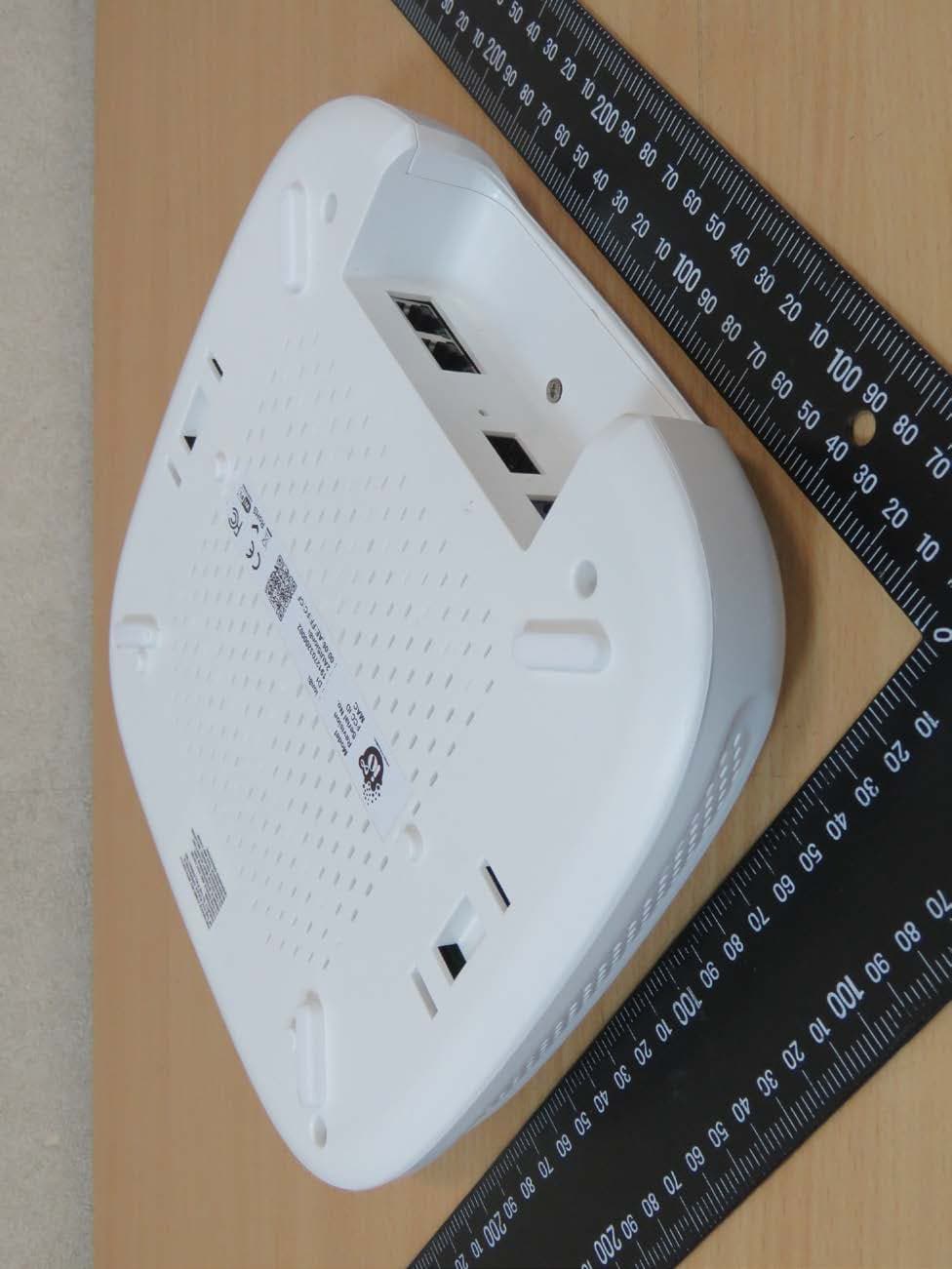
2AUISION8I
Jan 31, 2020Dual band 4X4 lndoor Access Point (AP) with integrated antenna
Equipment Class
NII - Unlicensed National Information Infrastructure TX