2AUNU433-RBWireless Reset Button
SMART CAREGIVER CORPORATION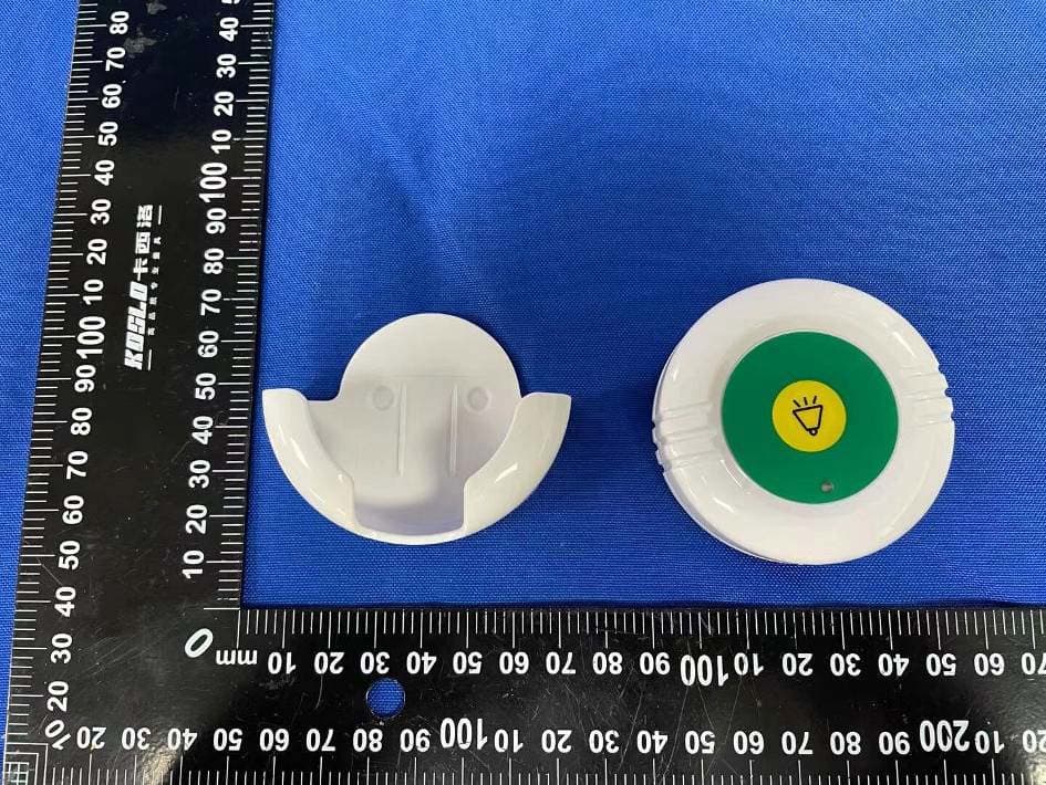
Click to zoom
Application Details
- Equipment Class
- DSC - Part 15 Security/Remote Control Transmitter
- Date of Grant
- Mar 01, 2023
- Application Purpose
- Original Equipment
- Date of Application
- Mar 01, 2023
- Equipment Note
- Wireless Reset Button
- Frequency Range
- 433.92000000 - 433.92000000
- Company
- SMART CAREGIVER CORPORATION
- Country
- United States
Documents & Files
Document Text
Text extracted from the exhibit documents filed with the FCC. Open a document above to read the original.
Users Manual
1. Open Reset Button fr om slot on bottom. (See Figure 1) 2. Install one 12V/23A Batt ery (S ee Figure 2) 3. Attach Lanyard Place loop in bottom of lanyard over pin at the top of the reset button. (See Figure 3)While holding lanyar d in place, snap reset button back together. 4. Mounting Reset button may be mounted using the screws or double sided tape provided. 5. Test Press reset button. Red light at the top of reset button should illuminate. Quick Start Instructions 433-RB Fall Prevention by Smart Caregiv er (800) 650-3637 | www.smartcaregiv er .c om (F igure 1)(F igure 2)(F igure 3) Red = Activated When Fades = Low Battery Not waterproof or water resistant. *Exposure to moisture for long periods of time is not recommended Works with 433-CMU and 433-EC 1. Open Reset Button fr om slot on bottom. (See Figure 1) 2. Install one 12V/23A Batt ery (S ee Figure 2) 3. Attach Lanyard Place loop in bottom of lanyard over pin at the top of the reset button. (See Figure 3)While holding lanyar d in place, snap reset button back together. 4. Mounting Reset button may be mounted using the screws or double sided tape provided. 5. Test Press reset button. Red light at the top of reset button should illuminate. Quick Start Instructions 433-RB Fall Prevention by Smart Caregiv er (800) 650-3637 | www.smartcaregiv er .c om (F igure 1)(F igure 2)(F igure 3) Red = Activated When Fades = Low Battery Not waterproof or water resistant. *Exposure to moisture for long periods of time is not recommended Works with 433-CMU and 433-EC 1. Open Reset Button fr om slot on bottom. (See Figure 1) 2. Install one 12V/23A Batt ery (S ee Figure 2) 3. Attach Lanyard Place loop in bottom of lanyard over pin at the top of the reset button. (See Figure 3)While holding lanyar d in place, snap reset button back together. 4. Mounting Reset button may be mounted using the screws or double sided tape provided. 5. Test Press reset button. Red light at the top of reset button should illuminate. Quick Start Instructions 433-RB Fall Prevention by Smart Caregiv er (800) 650-3637 | www.smartcaregiv er .c om (F igure 1)(F igure 2)(F igure 3) Red = Activated When Fades = Low Battery Not waterproof or water resistant. *Exposure to moisture for long periods of time is not recommended Works with 433-CMU and 433-EC Fall Prevention by Smart Caregiv er (800) 650-3637 | www.smartcaregiv er .c om Smart Caregiver 433-RB Reset Button Please be awar e that the 433-RB will reset an alarming 433-CMU Economy Centr al Monitor that has been triggered by one or more devices. For example, if a 433-CMU (and 433-PGD pager, if in use) has been triggered by a sensor pad and a motion sensor simultaneously, its display will show both devices have been triggered (by number). Car egivers may reset the Economy Centr al Monitor with a 433-RB, but it will reset the alert and clear from memory all currently active alerts . If multiple active alerts have been reset by the 433-RB, car egivers may still see which devices triggered recent alerts by pressing “REVIEW” button on the 433-PGD Car egiver Pager. 433-RB Reset Button 433-CMU Central Monitor 433-PGD Caregiver Pager Important Product Information IMPORTANT INFORMATION: Cordless and Wireless Systems rely on wireless technology which is subject to physical and environmental considerations. Please be aware that the transmitter will not be 100% accurate if it is out of range at any time. It is the end-user’s responsibility to make sure that the product is used correctly and within range of each other. Cordless and wireless systems and devices are intended as an adjunct to good caregiving practices and are not a substitute for proper sta ng and patient management practices. We recommend that all caregivers receive periodic training in the operation of these systems and that the devices are tested daily. It is important to read and follow the directions. Read the instructions and Legal Disclaimer. The Smart Caregiver Corporation devices are designed to be installed by the end user. As such, it is the entire responsibility of the buyer to insure that the system is properly installed and tested. Further, the system is not designed to replace good caregiving practices including, but not limited to: A.) Direct patient supervision B.) Adequate training for sta personnel for fall prevention and elopement C.) Testing of the system before each use WARNING: The manufacturer does not claim that this device will stop elopement and/or stop falls. This device is designed to augment caregivers’ comprehensive resident mobility management program. Failure to comply with the warning may result in injury or death. This device is not suitable for all individuals. Other devices may be required. This device is not a substitute for visual monitoring by a caregiver. Where permissible, it is the seller’s intent to limit any liability for special, consequential or incidental economic damages to refund of the purchase price or replacement of the goods. Seller disclaims any liability for compensatory or other damages arising out of the use of the goods. Limited Warranty: Seller warrants that the goods sold will be free from defects of workmanship and manufacturing, for a warranty period from the date of sale. Other than this limited warranty, seller makes no express or implied warranties. Except for this limited warranty. No express or implied warranties are given and no a rmation of seller, by words or action will constitute a warranty. The goods being purchased are being sold on a “with all faults” basis. The entire risk as to the quality and performance of the goods is with the buyer. Should the goods prove defective following their purchase, the buyer, and not the manufacturer, distributor or retailer, assumes the entire cost of all necessary installation, servicing or repairs. Fall Prevention by Smart Caregiv er (800) 650-3637 | www.smartcaregiv er .c om Smart Caregiver 433-RB Reset Button Please be awar e that the 433-RB will reset an alarming 4…
Text truncated - open the document above for the full version.
Attestation Statements
U.S. AGENT LETTER OF ATTESTATION Date: 2023-02-14 FEDERAL COMMUNICATIONS COMMISSION Authorization and Evaluation Division 7435 Oakland Mills Road Columbia, MD 21046 Ref: Attestation Statements Part 2.911(d)(7) Filing FCC ID: 2AUNU433-RB SMART CAREGIVER CORPORATION (“the Applicant”) certifies that, as of the date of the filing of the application, SMART CAREGIVER CORPORATION(U.S. agent). is our designated U.S. agent for service of process for the above referenced FCC ID. SMART CAREGIVER CORPORATION (“the Applicant”)accepts to maintain an agent for no less than one year after the grantee has terminated all marketing and importation or the conclusion of any Commission-related proceeding involving the equipment. SMART CAREGIVER CORPORATION (U.S. agent) accepts, as of the date of the filing of the application, the obligation of the designated U.S. agent for service of process for the above referenced FCC ID. Applicant and Designated U.S. Agent Information: Name: SMART CAREGIVER CORPORATION Address: 1229 N. MCDOWELL BLVD PETALUMA California United States 94954 Tel.: 707 781 7450 Email: [email protected] Signed by (printed name): [email protected] Signature:
External Photos
Shenzhen Accurate Technology Co., Ltd. Project No.: RA221124-56684E-RF External Photos Page 1 of 4 External Photos Shenzhen Accurate Technology Co., Ltd. Project No.: RA221124-56684E-RF External Photos Page 2 of 4 Shenzhen Accurate Technology Co., Ltd. Project No.: RA221124-56684E-RF External Photos Page 3 of 4 Shenzhen Accurate Technology Co., Ltd. Project No.: RA221124-56684E-RF External Photos Page 4 of 4
ID Label/Location Info
433-RB Made in China FCC ID:2AUNU433-RB 433-RB Made in China FCC ID:2AUNU433-RB label location
Internal Photos
Shenzhen Accurate Technology Co., Ltd. Project No.: RA221124-56684E-RF Internal Photos Page 1 of 3 Internal Photos Shenzhen Accurate Technology Co., Ltd. Project No.: RA221124-56684E-RF Internal Photos Page 2 of 3 Shenzhen Accurate Technology Co., Ltd. Project No.: RA221124-56684E-RF Internal Photos Page 3 of 3
RF Exposure Info
Shenzhen Accurate Technology Co., Ltd. Report No.: RA221124-56684E-RF Version 5: 2021-11-09 Page 8 of 19 FCC Part 15.231 FCC §1.1307 (b) & §2.1093 – RF EXPOSURE Applicable Standard According to FCC §2.1093 and §1.1307(b), systems operating under the provisions of this section shall be operated in a manner that ensure that the public is not exposed to radio frequency energy level in excess of the Commission’s guideline. According to KDB 447498 D04 Interim General RF Exposure Guidance v01, clause 2.1.2 – 1- mW test Exemption: Per § 1.1307(b)(3)(i)(A), a single RF source is exempt RF device (from the requirement to show data demonstrating compliance to RF exposure limits, as previously mentioned) if the available maximum time-averaged power is no more than 1 mW, regardless of separation distance. This exemption applies to all operating configurations and exposure conditions, for the frequency range 100 kHz to 100 GHz, regardless of fixed, mobile, or portable device exposure conditions. This is a standalone exemption, and it cannot be applied in conjunction with any other test exemption. Test Result: For worst case: Mode Frequency Maximum ERP 1-mW test Exemption (MHz) (dBm) (mW) SRD 433.92 -24.87 0.0033 Yes Note 1: use the maximum E-field strength (72.48dBuV/m) for the RF exposure evaluation Note 2: E(dBuV/m)=EIRP(dBm)-95.2 for distance 3m so the EIRP=72.48dBuV/m-95.2=-22.72dBm Note 3: EIRP(dBm)= ERP+2.15dBi so the ERP=-22.72dBm-2.15dBi=-24.87dBm Result: Compliant.
Test Report
Note: This report may contain data that are not covered by the A2LA accreditation and are marked with an asterisk “★”. Shenzhen Accurate Technology Co., Ltd. is not responsible for the authenticity of any test data provided by the applicant. Data included from the applicant that may affect test results are marked with an asterisk ’*’. Customer model name, addresses, names, trademarks etc. are not considered data. This report cannot be reproduced except in full, without prior written approval of the Company. Unless otherwise stated the results shown in this test report refer only to the sample(s) tested. This report is valid only with a valid digital signature. The digital signature may be available only under the Adobe software above version 7.0. Shenzhen Accurate Technology Co., Ltd. 1/F., Building A, Changyuan New Material Port, Science & Industry Park, Nanshan District, Shenzhen, Guangdong, P.R. China Tel: +86 755-26503290 Fax: +86 755-26503396 Web: www.atc-lab.com Version 5: 2021-11-09 Page 1 of 19 FCC Part 15.231 TEST REPORT Applicant Name : SMART CAREGIVER CORPORATION Address : 1229 N. MCDOWELL BLVD PETALUMA California United States 94954 Report Number : RA221124-56684E-RF FCC ID: 2AUNU433-RB Test Standard (s) FCC PART 15.231 Sample Description Product Type: Wireless Reset Button Model No.: 433-RB Trade Mark: SMART Date Received: 2022-11-24 Date of Test: 2022-12-12 to 2023-01-10 Report Date: 2023-01-11 Test Result: Pass* * In the configuration tested, the EUT complied with the standards above. Prepared and Checked By: Approved By: Bob.Liao Candy Li EMC Engineer EMC Engineer Shenzhen Accurate Technology Co., Ltd. Report No.: RA221124-56684E-RF Version 5: 2021-11-09 Page 2 of 19 FCC Part 15.231 TABLE OF CONTENTS GENERAL INFORMATION ....................................................................................................................................... 3 PRODUCT DESCRIPTION FOR EQUIPMENT UNDER TEST (EUT) ..................................................................................... 3 OBJECTIVE ................................................................................................................................................................... 3 TEST METHODOLOGY .................................................................................................................................................. 3 MEASUREMENT UNCERTAINTY .................................................................................................................................... 4 SYSTEM TEST CONFIGURATION .......................................................................................................................... 5 JUSTIFICATION ............................................................................................................................................................. 5 SPECIAL ACCESSORIES ................................................................................................................................................. 5 EQUIPMENT MODIFICATIONS ....................................................................................................................................... 5 SUPPORT EQUIPMENT LIST AND DETAILS .................................................................................................................... 5 EXTERNAL I/O CABLE.................................................................................................................................................. 5 BLOCK DIAGRAM OF TEST SETUP ................................................................................................................................ 5 SUMMARY OF TEST RESULTS ............................................................................................................................... 6 TEST EQUIPMENT LIST AND DETAILS ............................................................................................................... 7 FCC §1.1307 (B) & §2.1093 – RF EXPOSURE ........................................................................................................... 8 APPLICABLE STANDARD .............................................................................................................................................. 8 TEST RESULT: .............................................................................................................................................................. 8 FCC §15.203 - ANTENNA REQUIREMENT ............................................................................................................. 9 APPLICABLE STANDARD .............................................................................................................................................. 9 ANTENNA CONNECTOR CONSTRUCTION ...................................................................................................................... 9 FCC §15.205, §15.209, §15.231 (B) - RADIATED EMISSIONS ............................................................................. 10 APPLICABLE STANDARD ............................................................................................................................................ 10 EUT SETUP ................................................................................................................................................................ 10 EMI TEST RECEIVER SETUP ....................................................................................................................................... 11 TEST PROCEDURE ...................................................................................................................................................... 11 CORRECTED AMPLITUDE & MARGIN CALCULATION ................................................................................................. 12 TEST RESULTS SUMMARY ....................................................................................................…
Text truncated - open the document above for the full version.
Test Setup Photos
Shenzhen Accurate Technology Co., Ltd. Project No.: RA221124-56684E-RF Test Photos Page 1 of 1 Radiated Spurious Emissions Test View (Below 1GHz) Radiated Spurious Emissions Test View (Above 1GHz)
Contact Information
Applicant
Tim Long(Director)
Test Firm
Shenzhen Accurate Technology Co., Ltd.Lisa Zhang
[email protected]+86-755-26503290
Technical Specifications
| # | Rule Parts | Frequency Range | Power Output |
|---|---|---|---|
| 1 | 15.231 | 433.92 MHz - 433.92 MHz | - |
Other Applications from SMART CAREGIVER CORPORATION
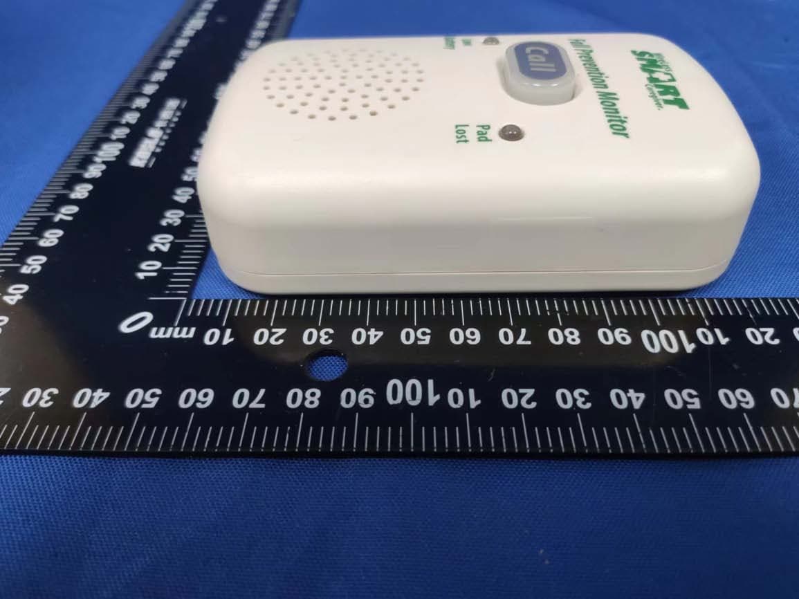
2AUNUTL-2020
Dec 07, 2022Wireless Economy Alarm Monitor
Equipment Class
DSC - Part 15 Security/Remote Control Transmitter