2AUNUTL-2020Wireless Economy Alarm Monitor
SMART CAREGIVER CORPORATION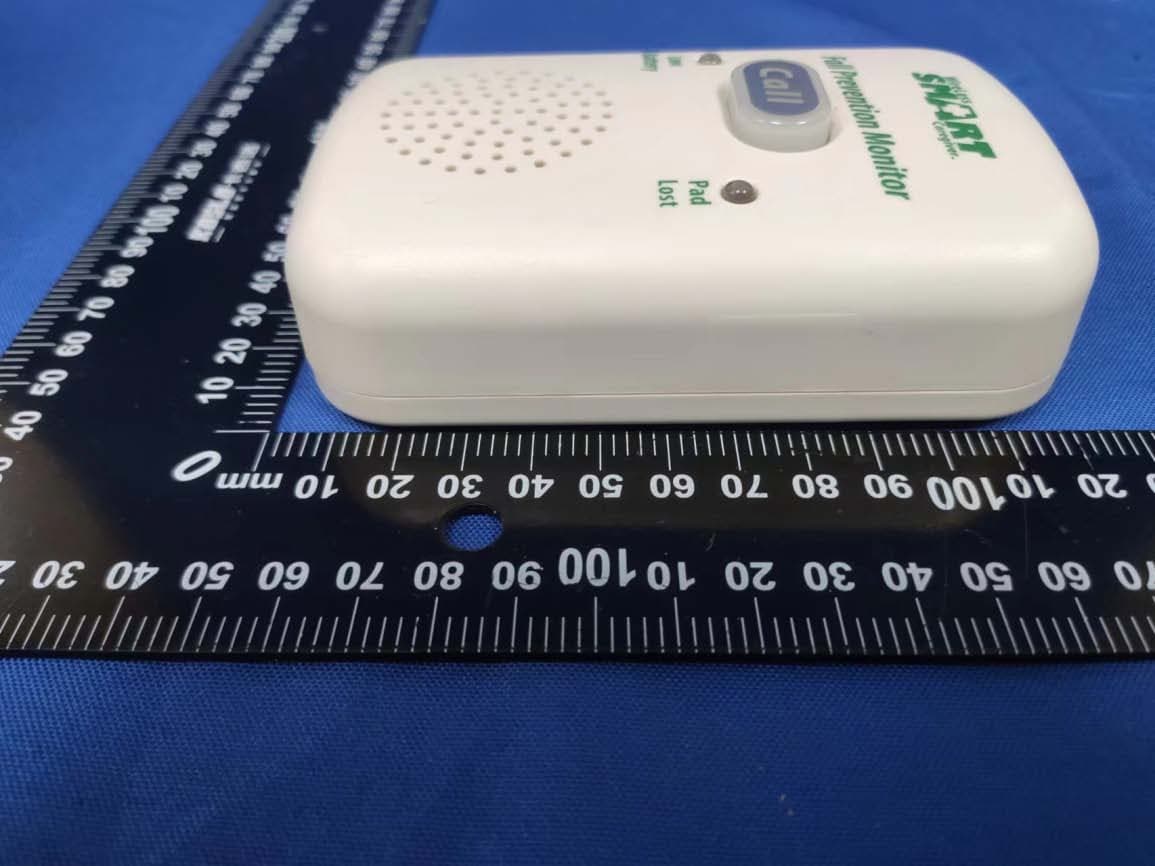
Click to zoom
Application Details
- Equipment Class
- DSC - Part 15 Security/Remote Control Transmitter
- Date of Grant
- Dec 07, 2022
- Application Purpose
- Original Equipment
- Date of Application
- Dec 07, 2022
- Equipment Note
- Wireless Economy Alarm Monitor
- Frequency Range
- 433.92000000 - 433.92000000
- Company
- SMART CAREGIVER CORPORATION
- Country
- United States
Documents & Files
Document Text
Text extracted from the exhibit documents filed with the FCC. Open a document above to read the original.
Users Manual
TL-2020 Wireless Economy Fall Prevention Monitor Installation and Use Instructions • Reduces in room alert noise • Monitor can be set to silent • Wireless paging directly from the monitor • Works with corded weight-sensing pads and floor mats TL-2020 Economy Wireless Fall Prevention Monitor Seat Belts SEAT BELT PLACEMENT • Unscrew one screw on either side of wheelchair that holds seat in place. • Attach seat belt to wheelchair by lining up the grommet holes on seat belt with the screw holes. Re-insert screws through both seat belt and wheelchair to hold seat belt in place. Make sure the screws are tightened. • Adjust seat belt to desired length using the black buckle that holds the adjustment strap in place. • Place the monitor out of reach of the resident. Suitable mounting location is the back of wheelchair, so that the resident cannot tamper with monitor. TEST THE SYSTEM • Buckle and unbuckle the seat belt to set off the alert. The alert will sound whenever the seat belt is unbuckled. • When the alert is activated, press the “Call” button on front of the monitor to silence the alert. The status light on front of monitor will blink when the seat belt is plugged into the monitor and buckled. Bed and Chair Weight-Sensing Pads BED PLACEMENT • Place the pad under shoulders to be alerted when the resident sits up in bed. • Place pad under lower back/buttocks to be alerted when the resident vacates the bed. • Place the monitor out of reach of resident. Suitable mounting locations include: back of headboard, wall or under bed. Make sure the resident cannot tamper with monitor. (It is the caregiver’s responsibility to route the cord under the sheet so the resident cannot tamper with it). WHEELCHAIR/CHAIR PLACEMENT • Center pad on the chair seat under buttocks. • Place the monitor out of reach of the resident. Suitable mounting location is the back of wheelchair, so that the resident cannot tamper with monitor. IMPORTANT: TEST THE SYSTEM • Plug the pad into the monitor and apply weight to the pad to activate the system. The monitor will beep twice when activated. • The alert tone will sound when weight is removed from pad. Press the “Call” button on front of monitor to silence the alert. The call button light on the front of monitor will blink when pad is plugged into monitor and pressure is on pad. CordLess™ Be d Pa d Wi reless Fall M onito r Ca ll L o w B a t te r y P a d L o s t Wi rel ess Fa ll M onitor Ca ll L o w B a t te r y P a d L o s t Wi rel ess F all M on itor Ca ll L o w B a t te r y Pa d L o s t 12 Need Set-up Help? (800) 650-3637 IMPORTANT INFORMATION: Cordless and Wireless Systems rely on wireless technology which is subject to physical and environmental considerations. Please be aware that the transmitter will not be 100% accurate if it is out of range at any time. It is the end-user’s responsibility to make sure that the product is used correctly and within range of each other. Cordless and wireless systems and devices are intended as an adjunct to good caregiving practices and are not a substitute for proper staffing and patient management practices. We recommend that all caregivers receive periodic training in the operation of these systems and that the devices are tested daily. It is important to read and follow the directions. Read the instructions and Legal Disclaimer. The Smart Caregiver Corporation devices are designed to be installed by the end user. As such, it is the entire responsibility of the buyer to insure that the system is properly installed and tested. Further, the system is not designed to replace good caregiving practices including, but not limited to: A.) Direct patient supervision B.) Adequate training for staff personnel for fall prevention and elopement C.) Testing of the system before each use WARNING: The manufacturer does not claim that this device will stop elopement and/or stop falls. This device is designed to augment caregivers’ comprehensive resident mobility management program. Failure to comply with the warning may result in injury or death. This device is not suitable for all individuals. Other devices may be required. This device is not a substitute for visual monitoring by a caregiver. Where permissible, it is the seller’s intent to limit any liability for special, consequential or incidental economic damages to refund of the purchase price or replacement of the goods. Seller disclaims any liability for compensatory or other damages arising out of the use of the goods. Limited Warranty: Seller warrants that the goods sold will be free from defects of workmanship and manufacturing, for a warranty period from the date of sale. Other than this limited warranty, seller makes no express or implied warranties. Except for this limited warranty. No express or implied warranties are given and no affirmation of seller, by words or action will constitute a warranty. The goods being purchased are being sold on a “with all faults” basis. The entire risk as to the quality and performance of the goods is with the buyer. Should the goods prove defective following their purchase, the buyer, and not the manufacturer, distributor or retailer, assumes the entire cost of all necessary installation, servicing or repairs. SMART CAREGIVER CORPORATION 1229 North McDowell Blvd., Petaluma, CA. 94954 | Tel: 800-650-3637 csr @ smartcaregiver.com | www.smartcaregiver.com Wi re le ss Fa ll Monit or Call L ow B a t te ry Pa d L o s t Bed Pa d Wi rel ess Fa ll M onito r Ca ll L ow B a t te r y Pa d L o s t Fl oor Ma t Wi reless Fa ll M oni tor Ca ll L o w B a t te r y Pa d L o s t Fl oor Ma t Wi rel ess Fall M on it or Ca ll L o w B a t t e r y Pa d L o s t Floor Mats FLOOR MAT PLACEMENT • Place the floor mat in the desired location such as a critical doorway or next to a bed. • Place the monitor out of reach of resident. Suitable mounting locations include the back of the headboard, wall or under the bed so the resident cannot tamper with the monitor. TEST THE SYSTEM • St…
Text truncated - open the document above for the full version.
External Photos
Shenzhen Accurate Technology Co., Ltd. Project No.: SZNS1220812-36596E-RF Page 1 of 3 External Photos Shenzhen Accurate Technology Co., Ltd. Project No.: SZNS1220812-36596E-RF Page 2 of 3 Shenzhen Accurate Technology Co., Ltd. Project No.: SZNS1220812-36596E-RF Page 3 of 3
ID Label/Location Info
Fall Prevention Monitor PadLow Batt eryLost Call 6V DC 300mA MA X + - ARTWORK Revised 4-13-22 www.smar tcar egiv er .c om IMPORTANT: Read the detailed user instructions for complete setup and all warnings before use. Warning: This product must be tested by the end user before each use in the setting in which it is to be used. F ailure to comply with warning may result in injury or death. This is not suitable for all fall risk individuals. The manufacturer does not claim that this device will st op elopement and/or stop falls. This device is designed to augment car egivers’ c omprehensive resident mobility management program and This device may utilize wireless technology which is subject to physical and environmental considerations. Be awar e transmitter will not be accurate if out of range. All personnel should receive periodic training in the operation of these systems. Read the instructions and legal disclaimers. Read Instructions Before Use: Batt ery not included. Use 3 x AA alkaline batt eries. Setup: Plug sensor pad into the fall monitor . Apply pressure to the sensor pad to test the system. The monitor will emit two beeps, indicating that the system is working. The Monitor Call Button will blink every 3 seconds when the system is activated and operating properly. MADE IN CHINA TL-2020 Manufactured to ISO 9001 CONFORMS TO UL 60601-1 FCC ID:2AUNUTL-2020
Internal Photos
Shenzhen Accurate Technology Co., Ltd. Project No.: SZNS1220812-36596E-RF Internal Photos Page 1 of 4 Internal Photos Shenzhen Accurate Technology Co., Ltd. Project No.: SZNS1220812-36596E-RF Internal Photos Page 2 of 4 Shenzhen Accurate Technology Co., Ltd. Project No.: SZNS1220812-36596E-RF Internal Photos Page 3 of 4 Shenzhen Accurate Technology Co., Ltd. Project No.: SZNS1220812-36596E-RF Internal Photos Page 4 of 4 Antenna
Test Report
Note: This report may contain data that are not covered by the A2LA accreditation and are marked with an asterisk “★”. Shenzhen Accurate Technology Co., Ltd. is not responsible for the authenticity of any test data provided by the applicant. Data included from the applicant that may affect test results are marked with an asterisk ’*’. Customer model name, addresses, names, trademarks etc. are not considered data. This report cannot be reproduced except in full, without prior written approval of the Company. Unless otherwise stated the results shown in this test report refer only to the sample(s) tested. This report is valid only with a valid digital signature. The digital signature may be available only under the Adobe software above version 7.0. Shenzhen Accurate Technology Co., Ltd. 1/F., Building A, Changyuan New Material Port, Science & Industry Park, Nanshan District, Shenzhen, Guangdong, P.R. China Tel: +86 755-26503290 Fax: +86 755-26503396 Web: www.atc-lab.com Version 5: 2021-11-09 Page 1 of 24 FCC Part 15.231 TEST REPORT Applicant Name : SMART CAREGIVER CORPORATION Address : 1229 N. MCDOWELL BLVD PETALUMA California United States 94954 Report Number : SZNS1220812-36596E-RF FCC ID: 2AUNUTL-2020 Test Standard (s) FCC PART 15.231 Sample Description Product Type: Wireless Economy Alarm Monitor Model No.: TL-2020 Trade Mark: SMART Date Received: 2022-08-12 Date of Test: 2022-09-20 to 2022-10-14 Report Date: 2022-10-14 Test Result: Pass* * In the configuration tested, the EUT complied with the standards a bove. Prepared and Checked By: Approved By: Audy.Yu Candy Li EMC Engineer EMC Engineer Shenzhen Accurate Technology Co., Ltd. Report No.: SZNS1220812-36596E-RF Ve r s i o n 5: 2021-11-09 Page 2 of 24 FCC Part 15.231 TABLE OF CONTENTS GENERAL INFORMATION ....................................................................................................................................... 3 PRODUCT DESCRIPTION FOR EQUIPMENT UNDER TEST (EUT) ..................................................................................... 3 OBJECTIVE ................................................................................................................................................................... 3 TEST METHODOLOGY .................................................................................................................................................. 3 MEASUREMENT UNCERTAINTY .................................................................................................................................... 4 SYSTEM TEST CONFIGURATION .......................................................................................................................... 5 JUSTIFICATION ............................................................................................................................................................. 5 SPECIAL ACCESSORIES ................................................................................................................................................. 5 EQUIPMENT MODIFICATIONS ....................................................................................................................................... 5 SUPPORT EQUIPMENT LIST AND DETAILS .................................................................................................................... 5 EXTERNAL I/O CABLE.................................................................................................................................................. 5 BLOCK DIAGRAM OF TEST SETUP ................................................................................................................................ 6 SUMMARY OF TEST RESULTS ............................................................................................................................... 7 TEST EQUIPMENT LIST AND DETAILS ............................................................................................................... 8 FCC §1.1307 (B) & §2.1093 – RF EXPOSURE ........................................................................................................... 9 APPLICABLE STANDARD .............................................................................................................................................. 9 TEST RESULT: .............................................................................................................................................................. 9 FCC §15.203 - ANTENNA REQUIREMENT ........................................................................................................... 10 APPLICABLE STANDARD ............................................................................................................................................ 10 ANTENNA CONNECTOR CONSTRUCTION .................................................................................................................... 10 FCC §15.207 (A) – AC LINE CONDUCTED EMISSIONS .................................................................................... 11 APPLICABLE STANDARD ............................................................................................................................................ 11 EUT SETUP ................................................................................................................................................................ 11 EMI TEST RECEIVER SETUP ....................................................................................................................................... 11 TEST PROCEDURE ...................................................................................................................................................... 12 FACTOR & MARGIN CALCULATION ........................................................................................................................... 12 TEST DATA .................................................................................…
Text truncated - open the document above for the full version.
Test Setup Photos
Shenzhen Accurate Technology Co., Ltd. Project No.: SZNS1220812-36596E-RF Page 1 of 2 Photo of Conducted Emission Measurement Shenzhen Accurate Technology Co., Ltd. Project No.: SZNS1220812-36596E-RF Page 2 of 2 Photo of Radiated Emission Measurement Below 1GHz Photo of Radiated Emission Measurement Above 1GHz
Contact Information
Applicant
Tim Long(Director)
Test Firm
Shenzhen Accurate Technology Co., Ltd.Lisa Zhang
[email protected]+86-755-26503290
Technical Specifications
| # | Rule Parts | Frequency Range | Power Output |
|---|---|---|---|
| 1 | 15.231 | 433.92 MHz - 433.92 MHz | - |
Other Applications from SMART CAREGIVER CORPORATION
2AUNU433-RB
Mar 01, 2023Wireless Reset Button
Equipment Class
DSC - Part 15 Security/Remote Control Transmitter