2AUTR-966Quantum TRM
SVAB Hydraulik AB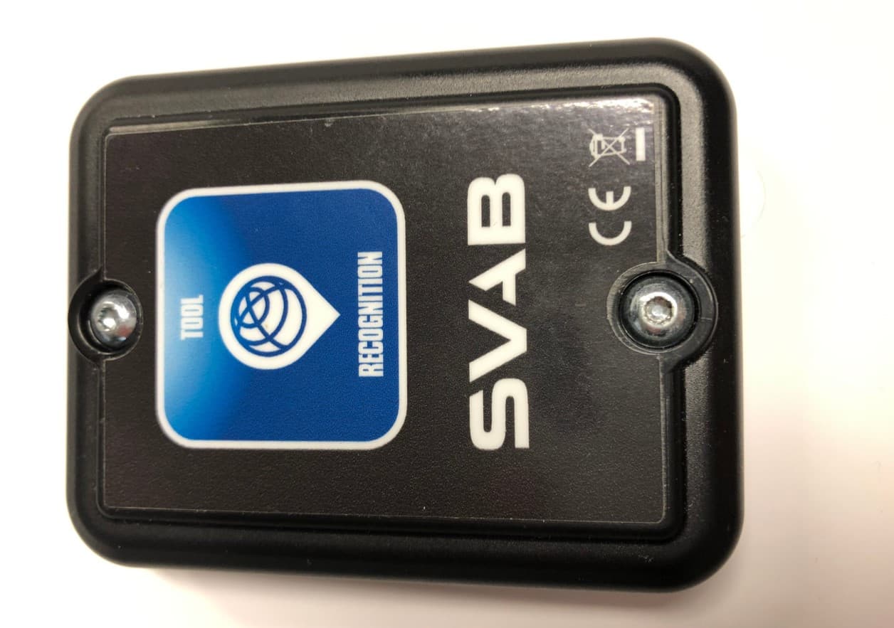
Click to zoom
Application Details
- Equipment Class
- DXX - Part 15 Low Power Communication Device Transmitter
- Date of Grant
- Dec 18, 2020
- Application Purpose
- Original Equipment
- Date of Application
- Dec 17, 2020
- Equipment Note
- Quantum TRM
- Frequency Range
- 2402.00000000 - 2480.00000000
- Company
- SVAB Hydraulik AB
- Country
- Sweden
Documents & Files
Document Text
Text extracted from the exhibit documents filed with the FCC. Open a document above to read the original.
Users Manual
Quantum Installation instruction DOC-0001404 2020-12-02 Copyright © 2020 SVAB Hydraulik AB All rights reserved SVAB accepts no responsibility for possible errors in catalogs, brochures and other printed material. SVAB reserves the right to alter its products without prior notice. This also applies to products already ordered provided that such alterations can be made without affecting agreed specifications. All trademarks in this material are properties of their respective owners. Table of Contents Introduction ........................................................................................................................... 4 General ......................................................................................................................... 4 Support ......................................................................................................................... 5 Environment .................................................................................................................. 5 Certificate of compliance ................................................................................................ 6 Safety ................................................................................................................................... 7 General safety ............................................................................................................... 7 Warning signs ................................................................................................................ 7 Levels of risks ............................................................................................................... 7 System overview ................................................................................................................... 9 Technical description ............................................................................................................ 10 Main parts ................................................................................................................... 10 Quantum Hub ...................................................................................................... 10 TRM (Tool Recognition Module) ............................................................................ 10 Technical data Quantum Hub ........................................................................................ 11 Technical data TRM ..................................................................................................... 13 Function ...................................................................................................................... 14 Installation ........................................................................................................................... 16 Check of delivery ......................................................................................................... 16 Install the Quantum hub ............................................................................................... 16 Install quick coupler switch ........................................................................................... 17 Connecting quick coupler; original and tiltrotator-system ................................................ 18 Connect feed and external excvatator system (when applicable) ..................................... 21 Connecting to tiltrotatorsystem (MACS-RT, XCG2) ......................................................... 22 Mount the TRM ............................................................................................................ 22 Start up ............................................................................................................................... 25 Start up the system ...................................................................................................... 25 Start the Quantum hub ................................................................................................. 25 Register user ............................................................................................................... 27 Register new machine .................................................................................................. 27 Register a new tool ...................................................................................................... 29 Electric diagram ................................................................................................................... 30 Checklist ............................................................................................................................. 31 Quantum 3 Introduction General Quantum Tool Recognition is a system for wireless toolrecognition on excavators. This is the only usage intended for this product. All other usages of this machine, without written permission from SVAB, are strictly prohibited. This document gives instructions how to do installation work on a Quantum Tool Recognition system. SVAB reserves the right to change the contents of this instruction at any time without further notice. SVAB develops and produces their products in accordance to european legislation and teh macinery directive 2006/42/EG. The CE marking shows that the system fulfills the directive of electromagnetic compatibility EMC, RoHS and radiodirective RED. This installation instruction shall be used in the technical file which will be the base for the final CE marking of the machine. Therefore, the checklist in this instruction shall be thouroughly performed, com- pletely filled out and signed by responsible fitter. Save this instruction in the technical file. The installation of the system referred to in this document is to be performed by experienced personnel. If there’s unclarities regarding the use, installation, understanding of the system or regarding this docu- ment - disengage the installation work and contact the system provider for i…
Text truncated - open the document above for the full version.
Users Manual
Quantum Tool Recognition User manual Quantum - Tool recognition Content Content Introduction 4 General 4 Support 5 Approved areas of use 5 Environment 6 Technical Description 7 System overview 7 Main parts 8 Technical data TRM 9 Technical data HUB 10 Funktion 11 Start using Quantum ToolRec 12 Start the Quantum hub 12 Quantum App 13 Service 20 Maintenance 21 Maintenance schedule 21 Maintenance instructions 21 Recommended spare parts 24 Recycling 24 Quantum - Tool Recognition Introduction Doc-0001374, Rev B Sida 4 Introduction Quantum Tool Recognition is a system for wireless toolrecognition on excavators. This is the only usage intended for this product. All other usages of this machine, without written permission from SVAB, are strictly prohibited. This document gives instructions how to do installation work on a Quantum Tool Recognition system. SVAB reserves the right to change the contents of this instruction at any time without further notice. SVAB develops and produces their products in accordance to european legislation and teh macinery directive 2006/42/EG. The CE marking shows that the system fulfills the directive of electromagnetic compatibility EMC, RoHS and radiodirective RED. This installation instruction shall be used in the technical file which will be the base for the final CE marking of the machine. Therefore, the checklist in this instruction shall be thouroughly performed, completely filled out and signed by responsible fitter. Save this instruction in the technical file. The installation of the system referred to in this document is to be performed by experienced personnel. If there’s unclarities regarding the use, installation, understanding of the system or regarding this document - disengage the installation work and contact the system provider for information. By using common sense you can avoid accidents from happening yourself. This instruction is protected by copyright and may not be reproduced, distributed or altered. Violation of the law may lead to prosecutions and fines, imprisonment or duty to pay compensation to the creator / proprietor. FCC and ISED Changes or modifications to the equipment not expressly approved by the party responsible for compliance could void the user’s authority to operate the equipment. This device complies with Part 15 of the FCC Rules. Operation is subject to the following two conditions: (1) this device may not cause harmful interference, and (2) this device must accept any interference received, including interference that may cause undesired operation. To comply with FCC/IC RF exposure limits for general population / uncontrolled exposure, the antenna(s) used for this transmitter must be installed to provide a separation distance of at least 20 cm from any persons and must not be co-located or operating in conjunction with any other antenna or transmitter. NOTE: This equipment has been tested and found to comply with the limits for a Class B digital device, pursuant to Part 15 of the FCC Rules. These limits are designed to provide reasonable protection against harmful interference in a residential installation. This equipment generates, uses and can radiate radio frequency energy and, if not installed General Quantum - Tool Recognition Introduction Doc-0001374, Rev B Sida 5 RSS standard This equipment is exempt from the routine RF exposure evaluation requirement of RSS-102. This equipment should be installed and operated with a minimum distance of 20 cm between the antenna and the user or bystanders. This device contains licence-exempt transmitter(s)/ receiver(s) that comply with Innovation, Science and Economic Development Canada’s licence- exempt RSS(s). Operation is subject to the following two conditions: (1) This device may not cause interference. (2) This device must accept any interference, including interference that may cause undesired operation of the device. Ce matériel n’est pas sujet à l’évaluation habituelle d’exposition RF selon RSS102. Ce matériel devrait être installé et exploité en gardant une distance minimale de 20 cm entre l’antenne et l’utilisateur ou lesspectateurs. L’émetteur/récepteur exempt de licence contenu dans le présent appareil est conforme aux CNR d’Innovation, Sciences et Développement économique Canada applicables aux appareils radio exempts de licence. L’exploitation est autorisée aux deux conditions suivantes : (1) L’appareil ne doit pas produire de brouillage; (2) L’appareil doit accepter tout brouillage radioélectrique subi, même si le brouillage est susceptible d’en compromettre le fonctionnement. CAN ICES-3 (B)/NMB-3(B) Contact SVAB at: SVAB, Ulvsättersgatan 2SE-694 35 Hallsberg Phone: +46 (0)582 152 30 (main) +46 (0)0582 152 33 (Support) On our website www.svab.se you will find additional information. Support Approved areas of use If you are unsure whether the function is allowed to control, always ask a technician from your system provider. Approved areas of use for Quantum ToolRec: - Tool recognition on excavator - Provide input signal to compatible systems Quantum shall only be used for approved areas of use and functions as mentioned above. SVAB will not take part in injuries or accidents that occurs due to unauthorized use. and used in accordance with the instructions, may cause harmful interference to radio communications. However, there is no guarantee that interference will not occur in a particular installation. If this equipment does cause harmful interference to radio or television reception, which can be determined by turning the equipment off and on, the user is encouraged to try to correct the interference by one or more of the following measures: -- Reorient or relocate the receiving antenna. -- Increase the separation between the equipment and receiver. -- Connect the equipment into an outlet on a circuit different from that to which the receiver is connected. -- Consult the dealer or an experienced radio/TV technician for help. Quantum - Tool Recognition Introduction Do…
Text truncated - open the document above for the full version.
External Photos
EXTERNAL PHOTOS Project no.: 371810 FCC ID: 2AUTR-966 Page 1 (1)
ID Label/Location Info
TRM Model: P-0000966
Internal Photos
INTERNAL PHOTOS Project no.: 371810 FCC ID: 2AUTR-966 Page 1 (1)
RF Exposure Info
FCC ID: 2AUTR‐966 MPE limits for FCC, 1.1310 Frequency FField StrengthEIRP 1 EIRPDistance DPD 2 PD Limit 3 Margin MHzdBμV/m @ 3mdBmmWcmmW/m^2 mW/cm^2dB 240294.1‐1.100.776200.000154138.1 Certification Number: 25895‐966 HVIN: 878375 MPE limits for Innovation, Science and Economic Development Canada, RSS‐102 Issue 5 Frequency FField StrengthEIRP 1 EIRPDistance DPD 2 PD Limit 3 Magin EIRP Exemption Limit 4 Exemption Limit Margin MHzdBμV/m @ 3mdBmWmW/m^2W/m^2dBWdB 240294.1‐1.100.0007760.20.001545.3535.42.6835.4 1 ANSI C63.10‐2013 Eq. 39, for d = 3 m, EIRP[dBm] = E[dB V/m]− 95.2 2 PD = EIRP / (4xπxD 2 ) [Health Canada Technical Guide ‐ Safety Code 6_2015, Eq. 5‐6 at 5.2; OET Bulletin 65, Edition 97‐01, August 1997, Eq (4)] 3 RSS‐102 Issue 5 Table 4, 0.02619xF 0.6834 ; FCC 1.1310 Table 1, General Public (Uncontrolled Environment) 4 RSS‐102 Issue 5 at 2.5.2, 1.31 ‐2 xF 0.6834
Test Report
Report No. 371810-02-R02 Template version: C Nemko Norway Nemko AS, Instituttveien 6, P.O. Box 96 Kjeller, 2027 Kjeller, Norway TEL +47 22 96 03 30 FAX +47 22 96 05 50 EMAIL [email protected] ENTERPRISE NUMBER NO974404532 nemko.com/no Test Report Product Tool Recognition Module with Bluetooth LE Transceiver Name and address of the applicant SVAB Hydraulik AB Ulvsättersgatan 2 69491 Hallsberg, Sweden Name and address of the manufacturer SVAB Hydraulik AB Ulvsättersgatan 2 69491 Hallsberg, Sweden Model Quantum TRM Rating 3.6V DC Trademark SVAB Serial number / Additional information Bluetooth Low Energy Tested according to FCC Part 15.249 Low Power Device Industry Canada RSS-210, Issue 10 Licence-Exempt Radio Apparatus: Category I Equipment Order number 371810 Tested in period 2019-07-23 to 2019-07-23 Issue date 2020-12-18 Name and address of the testing laboratory Instituttveien 6 Kjeller, Norway CAB Number: FCC: NO0001 ISED: NO0470 An accredited technical test executed under the Norwegian accreditation scheme Prepared by [Frode Sveinsen] Approved by [G.Suhanthakumar] This report shall not be reproduced except in full without the written approval of Nemko. Opinions and interpretations expressed within this report are not part of the current accreditation. This report was originally distributed electronically with digital signatures. For more information contact Nemko. TEST REPORT FCC Part 15.247 Report no.: 371810-02-R02 FCC ID: 2AUTR-966 IC: 25895-966 Nemko Norway, Instituttveien 6, Kjeller, Norway Page 2 (34) CONTENTS 1 INFORMATION ......................................................................................................................... 3 1.1 Test Item .................................................................................................................................... 3 1.2 Normal test condition ................................................................................................................. 4 1.3 Test Engineer ............................................................................................................................ 4 1.4 Antenna Requirement ................................................................................................................ 4 1.5 Test configuration ...................................................................................................................... 4 1.6 Comments ................................................................................................................................. 4 2 TEST REPORT SUMMARY ...................................................................................................... 5 2.1 General ...................................................................................................................................... 5 2.2 Test Summary ........................................................................................................................... 6 3 TEST RESULTS ........................................................................................................................ 7 3.1 Occupied Bandwidth (99% BW)................................................................................................. 7 3.2 Field Strength of Fundamental................................................................................................. 10 3.3 Restricted Bands of operation.................................................................................................. 13 3.4 Radiated Emissions, Band Edge ............................................................................................. 14 3.5 Radiated Emissions, 30 – 1000 MHz ....................................................................................... 16 3.6 Radiated Emissions, 1 – 26 GHz ............................................................................................. 18 4 Measurement Uncertainty ..................................................................................................... 32 5 LIST OF TEST EQUIPMENT................................................................................................... 33 6 BLOCK DIAGRAM .................................................................................................................. 34 6.1 Test Site Radiated Emission .................................................................................................... 34 TEST REPORT FCC Part 15.247 Report no.: 371810-02-R02 FCC ID: 2AUTR-966 IC: 25895-966 Nemko Norway, Instituttveien 6, Kjeller, Norway Page 3 (34) 1 INFORMATION 1.1 Test Item Name SVAB Hydraulik FCC ID 2AUTR-966 ISED ID 25895-966 Model/version Quantum TRM Serial number N/A Hardware identity and/or version 2.5.0 Software identity and/or version 2.1.1 Frequency Range 2402–2480 MHz Number of Channels 40 Operating Modes Bluetooth Low Energy Type of Modulation Digital (Gaussian Frequency Shift Keying) Conducted Output Power 0.77 mW (Peak) Antenna Connector None Number of Antennas 1 Antenna Diversity Supported No Power Supply Primary Battery (3.6V AA Lithium Cell) Description of Test Item The tested device is a BT Low Energy Tool Recognition Module. Description Brand Model Regulatory Information Bluetooth Controller Texas Instruments Dual-Mode Bluetooth Controller N/A TEST REPORT FCC Part 15.247 Report no.: 371810-02-R02 FCC ID: 2AUTR-966 IC: 25895-966 Nemko Norway, Instituttveien 6, Kjeller, Norway Page 4 (34) 1.2 Normal test condition Temperature: 20–25 °C Relative humidity 20–50 % Normal test voltage 3.6 V DC (Nominal BatteryVoltage) All tests were performed with the EUT powered from a new battery. Values above are the limit registered during the test period. 1.3 Test Engineer Frode Sveinsen 1.4 Antenna Requirement Does the EUT have detachable antenna(s)? ☐ YES ☒ NO If detachable, is the antenna connector(s) non-standard? ☐ YES ☐ NO The tested equipment has only integral antennas. Conducted tests with a temporary antenna connector. Requirement: FCC 15.203, 1…
Text truncated - open the document above for the full version.
Test Setup Photos
TEST SET-UP PHOTOS Project no.: 371810 FCC ID: 2AUTR-966 Page 1 (2) Radiated Emission, Below 1 GHz Radiated Emissions, 1 - 18 GHz TEST SET-UP PHOTOS Project no.: 371810 FCC ID: 2AUTR-966 Page 2 (2) Radiated Emissions, above 18 GHz
Contact Information
Applicant
Lennart Hedlund(R&D Manager)
Test Firm
Nemko Scandinavia ASTor Erik Pedersen
[email protected]+4798228176
Technical Specifications
| # | Rule Parts | Frequency Range | Power Output |
|---|---|---|---|
| 1 | 15C | 2.40 GHz - 2.48 GHz | - |
Other Applications from SVAB Hydraulik AB
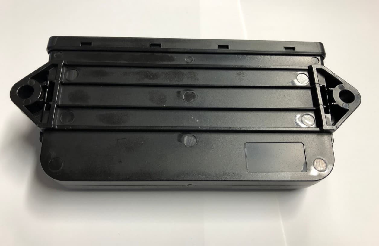
2AUTR-963
Dec 18, 2020Quantum HUB
Equipment Class
DTS - Digital Transmission System