Text extracted from the exhibit documents filed with the FCC. Open a document above to read the original.
User manual Model: ESL-SPETAP-WH-75W-V1 1. This product (module) is used in ESL Visions ESL-DVAN-SLR/PNL product series. The module can be connected to a DVAN driver to achieve 0-10 dimming. It can also work with an ESL VISION App to perform other functionalism. 2. To download ESL Vision’s APP, you can visit www.eslvision.com or find it in the app store 3. Once the module is learned-in via the ESL Vision APP. The user will be able to set specified settings such as 0-10V Dimming, high and trim, LED driver ON / OFF, and real-time power monitoring, grouping and other such features. 4. Please make sure this product is set up with the corresponding DVAN driver model. 5. For how to use ESL Vision’s app to control the TAP Module, please refer to the ESL Vision app manual. 6. Bluetooth Version: V4.1 APP introduction: The Login page: 1: new account registration 2: account login, forgot password, you can retrieve password 3: For new account registration, you can choose Mobile number or Email address to register according to the country or region. Mobile number, Email address accept the verification code, and also serve as a login account. 4: When registering, set the account password at the same time. 5:PRESETS 6:DEVICES 7:GROUPS 8:SCENES 9:SCHEDULES 10:ALERTS 11:REPORTS 12:ACCOUNT 13:ABOUT FCC STATEMENT This device complies with Part 15 of the FCC rules. Operation is subject to the following two conditions: 1) this device may not cause harmful interference, and 2) this device must accept any interference received, including interference that may cause undesired operation. Changes or modifications not expressly approved by the party responsible for compliance could void your authority to operate the equipment. The device has been evaluated to meet general RF exposure requirement, the device can be used in portable exposure condition without restriction. NOTE: This equipment has been tested and found to comply with the limits for a Class B digital device, pursuant to Part 15 of the FCC Rules. These limits are designed to provide reasonable protection against harmful interference in a residential installation. This equipment generates uses and can radiate radio frequency energy and, if not installed and used in accordance with the instructions, may cause harmful interference to radio communications. However, there is no guarantee that interference will not occur in a particular installation. If this equipment does cause harmful interference to radio or television reception, which can be determined by turning the equipment off and on, the user is encouraged to try to correct the interference by one or more of the following measures: Reorient or relocate the receiving antenna. Increase the separation between the equipment and receiver Connect the equipment into an outlet on a circuit different from that to which the receiver is connected. Consult the dealer or an experienced radio/TV technician for help.
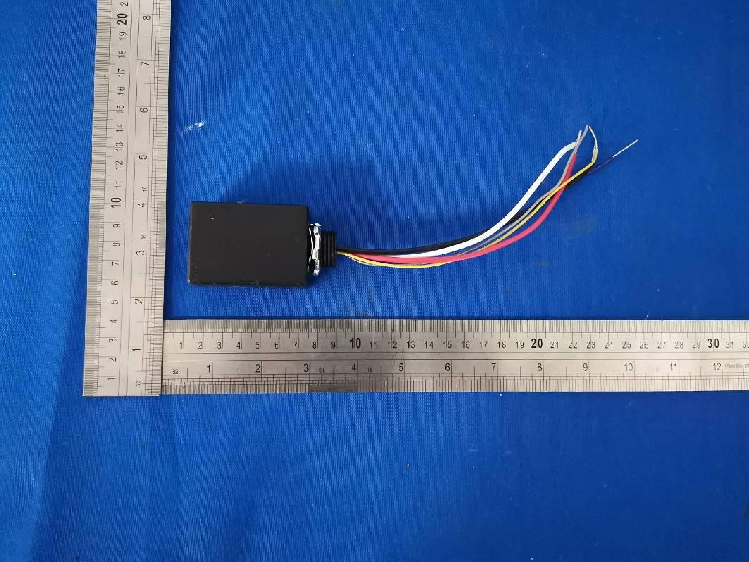
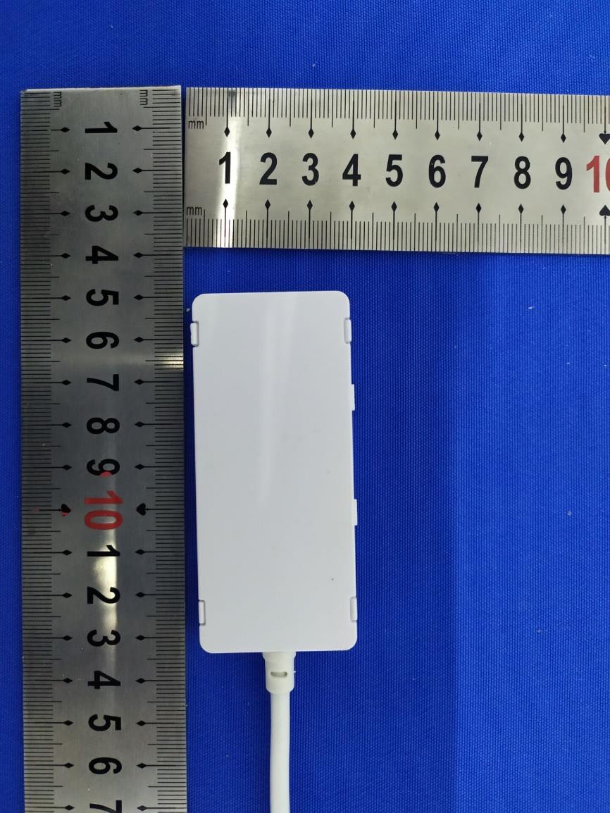
External photos
Label and label location
Internal Photos BT Antenna
Report No.:NTCER1911011 Dongguan New Testing Centre Co., Ltd E-mail: [email protected] 3F, No. 1 the 1st North Industry Road, Songshan Lake Science & Technology Park, Dongguan, Guangdong, China, 523808 FCC PART 15 SUBPART C TEST REPORT Issued By: Dongguan New Testing Centre Co., Ltd Add: 3F, No. 1 the 1st North Industry Road, Songshan Lake Science & Technology Park, Dongguan, Guangdong, China, 523808. A2LA Number:5426.01 Tel: 86-769-22212079 http://www.ntc-cert.com Marking: 1. The test report is invalid without the official stamp of test center. 2. Nobody is allowed to photocopy or partly photocopy this test report without written permission of test center. 3. The test report is invalid without the signatures of approver, reviewer and testing engineer. 4. The test report is invalid if altered. 5. Objections to the test report must be submitted to NTC within 15 days. 6. The test report is valid for the tested samples only. 7. As for test verdict, “—”means is “no need for judgment” “N/A” means is “not applicable”, “P” means “pass”, “F” means “fail”. Dongguan New Testing Centre Co., Ltd E-mail: [email protected] 3F, No. 1 the 1st North Industry Road, Songshan Lake Science & Technology Park, Dongguan, Guangdong, China, 523808 Page 1 of 91 Report No.:NTCER1911011 TABLE OF CONTENTS Test Report Declare ...................................................................................................................... 3 1. Summary Of Test Results ....................................................................................................... 4 2. General Test Information ......................................................................................................... 4 2.1. Description of EUT ................................................................................................................... 4 2.2. Assistant equipment used for test .......................................................................................... 6 2.3. Block diagram EUT configuration for test ............................................................................. 6 2.4. Test environment conditions ................................................................................................... 7 2.5. Measurement uncertainty ........................................................................................................ 8 3. Power Line Conducted Emission Test .................................................................................. 9 3.1. Test equipment ......................................................................................................................... 9 3.2. Block diagram of test setup ..................................................................................................... 9 3.3. Power line conducted emission limits (class B) ................................................................... 9 3.4. Test procedure ........................................................................................................................ 10 3.5. Test result ................................................................................................................................ 10 4. Radiated Emission Test ......................................................................................................... 13 4.1. Test equipment ....................................................................................................................... 13 4.2. Block diagram of test setup ................................................................................................... 14 4.3. Limit .......................................................................................................................................... 16 4.4. Test procedure ........................................................................................................................ 17 4.5. Test result ................................................................................................................................ 17 5. Maximum Peak Output Power .............................................................................................. 23 5.1. Applied procedures / limit ...................................................................................................... 23 5.2. Test procedure ........................................................................................................................ 23 5.3. Deviation from standard ......................................................................................................... 23 5.4. Test setup ................................................................................................................................ 23 5.5. Test Results ............................................................................................................................. 23 6. -6dB Bandwidth Test .............................................................................................................. 26 6.1. Applied procedures / limit ...................................................................................................... 26 6.2. Test procedure ........................................................................................................................ 26 6.3. Deviation from standard ......................................................................................................... 26 6.4. Test setup ................................................................................................................................ 26 6.5. Test results .............................................................................................................................. 26 7. Power Spectral Density ......................................................................................................... 29 Dongguan New Testing Centre Co., Ltd E-mail: [email protected] 3F, No. 1 the 1st North Industry Road, Songshan Lake …
Text truncated - open the document above for the full version.
Setup photos Model: ESL-DVAN-SLR-xx-yyW-2YK Conducted emission test Radiated emission test 30MHz – 1GHz Above 1GHz
| # | Rule Parts | Frequency Range | Power Output |
|---|---|---|---|
| 1 | 15C | 2.40 GHz - 2.48 GHz | 600.00 µW |

Power Pack
Equipment Class
DTS - Digital Transmission System