2AVDH-JREMO4LIndustrial wireless remote controller
JEICO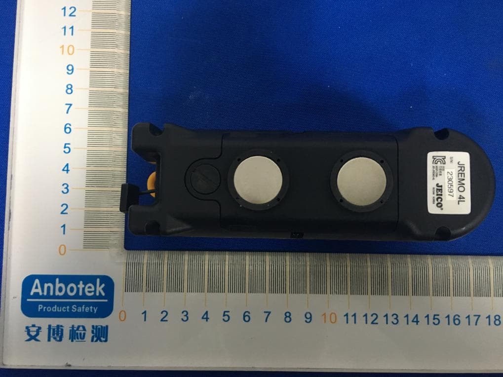
Click to zoom
Application Details
- Equipment Class
- DSC - Part 15 Security/Remote Control Transmitter
- Date of Grant
- Feb 26, 2020
- Application Purpose
- Original Equipment
- Date of Application
- Feb 26, 2020
- Equipment Note
- Industrial wireless remote controller
- Frequency Range
- 433.05000000 - 434.77500000
- Company
- JEICO
- Country
- South Korea
Documents & Files
Document Text
Text extracted from the exhibit documents filed with the FCC. Open a document above to read the original.
Users Manual
O&M MANUAL JREMO 4L REMOTE CONTROL www.jeico.com JEICO® INDUSTRIAL REMOTE CONTROLLER MODEL JREMO 4LJREMO 4L Serial No. Channel No. Lot No. JREMO® Remote Controllers must be handled, installed, operated, and maintained by (an) authorized and (a) qualified person(s), and Upon the above condition guaranty period from the date of (delivery, installation, inspection) shall be one calendar year. Subject to confirming defects not caused by improper installation, improper operation and/or insufficient maintenance, unauthorized modification, ignorance of environmental specifications, or improper interfacing, irresistible forces such as war(s), strike(s), Act(s) of God, and so on; all such the defects shall be treated as in no warranty. WARRANTY 03 JREMO 4L Industrial radio remote controller Contents PRECAUTIONS .........................................................04 CHAPTER I. GENERAL SPECIFICATIONS ...............06 1.1. COMMON SPECIFICATION ....................................06 1.2 Transmitter (Tx) ...................................................06 1.3 RECEIVER (Rx) ......................................................06 1.4 Model Suffixing ...................................................06 CHAPTER 2. JREMO 4L Standard Set ..................07 2-1 Standard set ......................................................07 2-2 CONTROL CONTACTS WIRE DIAGRAMS ..................08 CHAPTER 3. INSTALLATION & FUNCTION SETTING ......... 09 3-1 CAUTIONS FOR INSTALLATION .................................... 09 3-2 HOW TO INSTALL JREMO® SERIES TX ........................ 10 3-3 HOW TO INSTALL JREMO® SERIES RX ........................ 11 3-4 HOW TO START & USE PASSWORD(PWD) .................. 12 CHAPTER 4. MAINTENANCE .......................................... 13 4-1 STANDARD OPERATION ................................................ 13 4-2 FUSES ........................................................................... 13 CHAPTER 5. TROUBLESHOOTING .............................. 14 5-1 SELF DIAGNOSIS (LED SIGNAL ERROR MESSAGE) ...... 14 5-2 LED Diagnosis ............................................................... 14 5-3 Troubleshooting ............................................................ 15 APPENDIX I - 433 BAND FREQUENCY TABLE ..................... 16 APPENDIX II - OPTIONAL ACCESSORIES .............................. 17 04 JREMO 4L Industrial radio remote controller A. ANNOUNCEMENT ▪ This O&M Manual is for JREMO 4L and the specification is referred to Chapter 1. ▪ Before installation and operation look through this manual and make sure having a full acknowledgement of this manual. ▪ JREMO® series' remote controllers compose a High-Tech systemized, and a full knowledge of this manual is a must in advance of installation as well as operation of this remote controllers. ▪ Do not try to dismantle or unscrew JREMO® series except a skilful, an expert, and an authorized. ▪ This manual is for reference and good for installation and for maintenance, for better functions and qualities it may be changed, modified, revised without notice in advance. For more details consult an adjacent agent and/ or supplier. ▪ Each and all the JREMO® series' remote controller is tested under severe condition and passed without any default found at factory and is ready for an immediate use for a normal/insufficient condition or so, however, in an emergency and/or in an any dangerous possibility, do not use. ▪ After use switch off the main power of the equipment(ex. winch) and confirm the receiver power off, and also confirm EMS button of the transmitter is in a pressed down position. ▪ When not in use stay the transmitter in a safety area and do not allow an unauthorized to attempt to use it. ▪ Equipment(ex. winch) using this remote controller must have main relays, limit switches, separate COM lines, and other appropriate devices for safety operation. ▪ When metal container for receiver casing is used make sure Ground(GND) to be sure connected to metal part of equipment(ex. winch). ▪ Do not use in a severe interfered area and/or lightening or so. ▪ Make sure power sources are correct. ▪ Power off and do not use during installation and/or maintenance so as to avoid any electric shock or so. ▪ Do not try to copy, modify, or release this remote controllers without permis- sion in advance by JEICO, such an action is illegal. JREMO® series' remote controller have many international patents, certificates, and so on. PRECAUTIONS 05 JREMO 4L Industrial radio remote controller B. GENERAL CAUTIONS ▪ Every operator must be healthy both physically and mentally. ▪ Even though this remote controller is versatile, durable, and good for outdoor use try to avoid to contact directly by an excessive shock, pressure, wind, snow, rain, ices, or sunlight, high temperature, humid, gas, and etc. ▪ During operation when found power is weak Recharge battery by using of a suitable charger. ▪ When not in use for a long time Make sure the transmitter is full charged before use. ▪ In an emergency follow up the below emergency measures. C. EMERGENCY MEASURES JREMO® Series has designed for safety, meeting with various kind of emer- gencies and for self-recovering. Billions of different I.D. code, Self-Diagnoses, super qualified and isolated protection against voltage surges and/or inter- feres, etc. are the basic integral functions for solving any unexpected accident or trouble in an emergency. So when such an emergent function is detected, JREMO® series will off the work immediately and stop all the function auto- matically. For emergency follow up the below procedure in advance and then call an adjacent JEICO® agent and/or supplier for an emergency service. 1. Press down EMS Button(red mushroom button placed at top). 2. Power off receiver power. Power off main power of Equipment. 3. Inquire adjacent JEICO® agent and or supplier who can help. PRECAUTIONS ▪ Without notice in advance and within JEICO's discretion this manual may be revised, added…
Text truncated - open the document above for the full version.
Cover Letter(s)
SCS-F18: Project and Product Certification Representative Authorization Letter Page 1 of 2 Rev 6.0 775 Montague Expressway Milpitas, CA 95035 Tel: 408-526-1188 Fax: 408-526-1088 Email: [email protected] Project and Product Certification Representative Authorization Letter Reason for Amendment (current / obsolete) Revision History Approved Date FromTo Initial Release (obsolete)1.01.0Nov-14-2006 Revised wording (obsolete)1.02.0Sept–25-2007 Updated company template (obsolete)2.03.0Jan-31-2012 Updated letter information (obsolete)3.04.0May-23-2014 Added FCC ID field (obsolete)4.05.0Sep-16-2014 Updated company name & logo (current)5.06.0Jun-27-2018 SCS-F18: Project and Product Certification Representative Authorization Letter Page 2 of 2 Rev 6.0 (JEICO) (2020-02-18) To: BVCPS, INC. 775 Montague Expressway, Milpitas, CA 95035 USA Dear Sir/Madam, Re: Product Certification Representative Authorization Letter We, _____JEICO_____hereby authorize Bureau Veritas Consumer Product Services, Inc. to act as a Certification Body for certifying for the following project(s): FCC ID: 2AVDH-JREMO4L Product Description: Industrialwireless remote controller Model: JREMO 4L, JREMO 4LA, JREMO 4LB, JREMO 4LC, JREMO 4LM Sincerely, Client’s signature Byun Juyong/Manager Company Name: JEICO Address: 94-1, Choryang-ro, Dong-gu, Busan 48805, South Korea
Cover Letter(s)
SCS-F19: Confidentiality Request LetterPage 1 of 2 Rev 6.0 775 Montague Expressway Milpitas, CA 95035 Tel: 408-526-1188 Fax: 408-526-1088 Email: [email protected] Confidentiality Request Letter Reason for Amendment (current / obsolete) Revision History Approved Date FromTo Initial Release (obsolete)1.01.0Nov-14-2006 Adding CFR 2.459 (obsolete)1.02.0August – 11 - 2008 Updated company template & Added text box (obsolete) 2.03.0Jan-31-2012 Added IC confidentiality letter form (obsolete)3.04.0March-26-2015 Corrections to STC form. Added reference to KDB (obsolete) 4.05.0Nov-19-2015 Updated company logo (current)5.06.0Jun-26-2019 SCS-F19: Confidentiality Request LetterPage 2 of 2 Rev 6.0 (JEICO) (2020-02-18) To: Federal Communications Commission Authorization and Evaluation Division 7435 Oakland Mills Road Columbia, MD Subject:Permanent Confidentiality Requestfor FCC ID:2AVDH-JREMO4L Pursuant to sections 0.457 and 0.459 of CFR 47, we respectfully request permanent confidential treatment of the following Exhibits accompanying this application as: -Block Diagram -Schematics -Operational Description The above materials contain trade secrets and proprietaryinformation not customarily released to the public. The public disclosure of these materials may be harmful tothe applicant and provide unjustified benefits to its competitors. The applicant understands that disclosure of this application and all accompanying documentation will not be made before the date of the Grant for this application. Sincerely, Client’s signature Byun Juyong/Manager Company Name: JEICO Address: 94-1, Choryang-ro, Dong-gu, Busan 48805, South Korea
Cover Letter(s)
JEICO Declaration on Model Differences We, JEICO 94-1, Choryang-ro, Dong-gu, Busan 48805, South Korea Declare that the following product(s): Product Name:Industrial wireless remote controller Model No.:JREMO 4L, JREMO 4LA, JREMO 4LB, JREMO 4LC, JREMO 4LM FCC ID:2AVDH-JREMO4L Utilize the identical circuit design, PCB layout, shielding and interface with(JREMO 4L),only the appearance color and buttons type different. Therefore this application can be regarded as identical in performance to the submitted test sample. The manufacturer would take all the responsibilities for the above product(s). For and on behalf of Busan 48805, South Korea Authorized personLocation Name:Byun Juyong Position:Manager Date of issue:2020-02-18 *I hereby declare that I am entitled to sign on behalf of the applicant and that the information supplied is correct and complete.
ID Label/Location Info
Product Name: Industrial wireless remote controller Model No.: JREMO 4L FCC ID: 2AVDH-JREMO4L This device complies with Part 15 of the FCC Rules. Operation is subject to the following two conditions: (1) This device may not cause harmful interference, and (2)This device must accept any interference received, including interference that may cause undesired operation.
ID Label/Location Info
Label Location On EUT
Test Report
Report No.: SZAWW191130009-01FCC ID: 2AVDH-JREMO4LPage 1 of 39 Code:AB-RF-05-a FCC Test Report Client Name: JEICO Address: 94-1, Choryang-ro, Dong-gu, Busan 48805, Korea Product Name: Industrial wireless remote controller Date: Feb. 17, 2020 Shenzhen Anbotek Compliance Laboratory Limited Report No.: SZAWW191130009-01FCC ID: 2AVDH-JREMO4LPage 2 of 39 Code:AB-RF-05-a Contents 1. General Information ............................................................................................................................................... 4 1.1. Client Information ....................................................................................................................................... 4 1.2. Description of Device (EUT) ..................................................................................................................... 4 1.3. Auxiliary Equipment Used During Test ................................................................................................... 4 1.4. Description of Test Modes ........................................................................................................................ 5 1.5. List of channels ........................................................................................................................................... 6 1.6. Description Of Test Setup ......................................................................................................................... 7 1.7. Test Equipment List .................................................................................................................................... 8 1.8. Measurement Uncertainty ......................................................................................................................... 9 1.9. Description of Test Facility ........................................................................................................................ 9 2. Summary of Test Results ................................................................................................................................... 10 3. Conducted Emission Test ................................................................................................................................... 11 3.1. Test Standard and Limit .......................................................................................................................... 11 3.2. Test Setup .................................................................................................................................................. 11 3.3. Test Procedure .......................................................................................................................................... 11 3.4. Test Data .................................................................................................................................................... 11 4. Radiation Spurious Emission and Band Edge ................................................................................................ 12 4.1. Test Standard and Limit .......................................................................................................................... 12 4.2. Test Setup .................................................................................................................................................. 13 4.3. Test Procedure .......................................................................................................................................... 14 4.4. Test Data .................................................................................................................................................... 14 5. 20DB Occupy Bandwidth Test ........................................................................................................................... 26 5.1. Test Standard and Limit .......................................................................................................................... 26 5.2. Test Setup .................................................................................................................................................. 26 5.3. Test Procedure .......................................................................................................................................... 26 5.4. Test Data .................................................................................................................................................... 26 6. Dwell Time Test .................................................................................................................................................... 29 6.1. Test Standard and Limit .......................................................................................................................... 29 6.2. Test Setup .................................................................................................................................................. 29 6.3. Test Procedure .......................................................................................................................................... 29 6.4. Test Data .................................................................................................................................................... 29 7. Antenna Requirement ......................................................................................................................................... 32 7.1. Test Standard and Requirement ............................................................................................................ 32 7.2. Antenna Connected Construction .......................................................................................................... 32 APPENDIX I -- TEST SETUP PHOTOGRAPH ................................................................................................... 33 APPENDIX II -- EXTERNAL PHOTOGRAPH ........................…
Text truncated - open the document above for the full version.
Test Setup Photos
Photo of Radiated Emission Measurement
Contact Information
Applicant
Byun Juyong(manager)
Test Firm
Shenzhen Anbotek Compliance Laboratory LimitedJeff Zhu
Technical Specifications
| # | Rule Parts | Frequency Range | Power Output |
|---|---|---|---|
| 1 | 15.231 | 433.05 MHz - 434.775 MHz | - |
Other Applications from JEICO
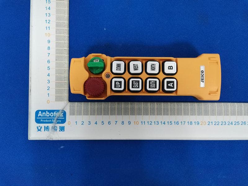
2AVDH-JREMO8K
Jul 27, 2021Industrial wireless remote controller
Equipment Class
DSC - Part 15 Security/Remote Control Transmitter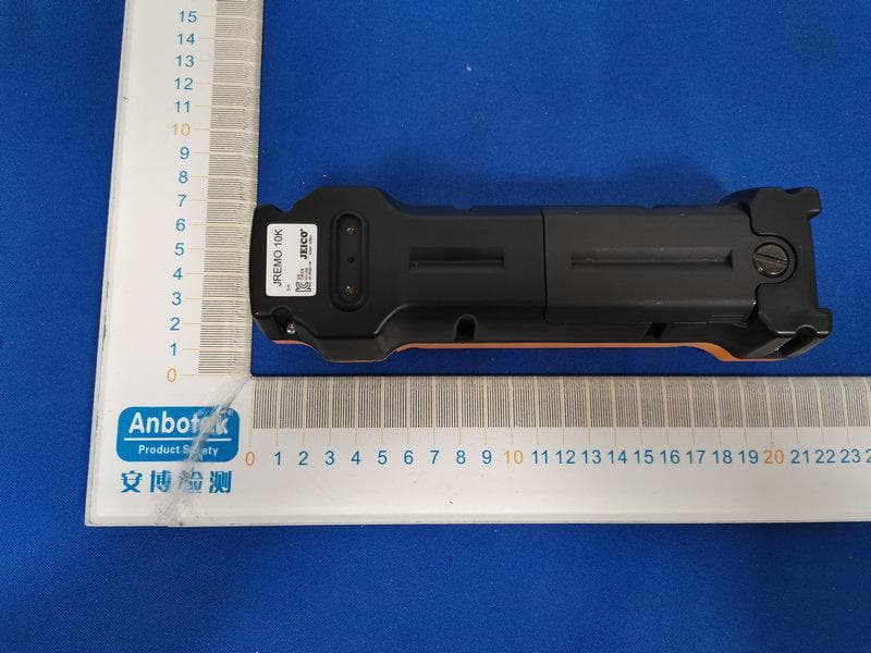
2AVDH-JREMO10K
Jul 27, 2021Industrial wireless remote controller
Equipment Class
DSC - Part 15 Security/Remote Control Transmitter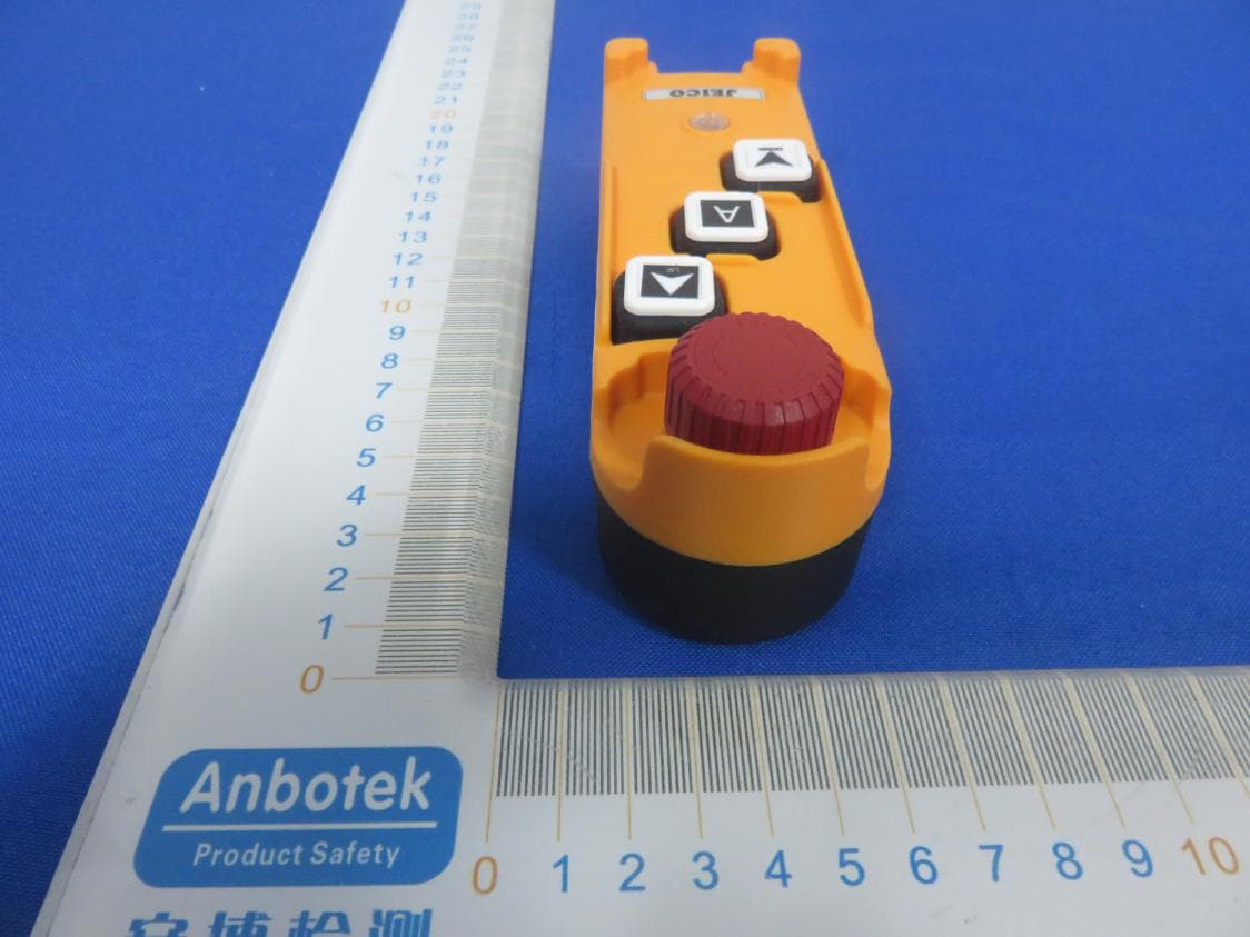
2AVDH-JREMO3K
Jan 08, 2020Industrial wireless remote controller
Equipment Class
DSC - Part 15 Security/Remote Control Transmitter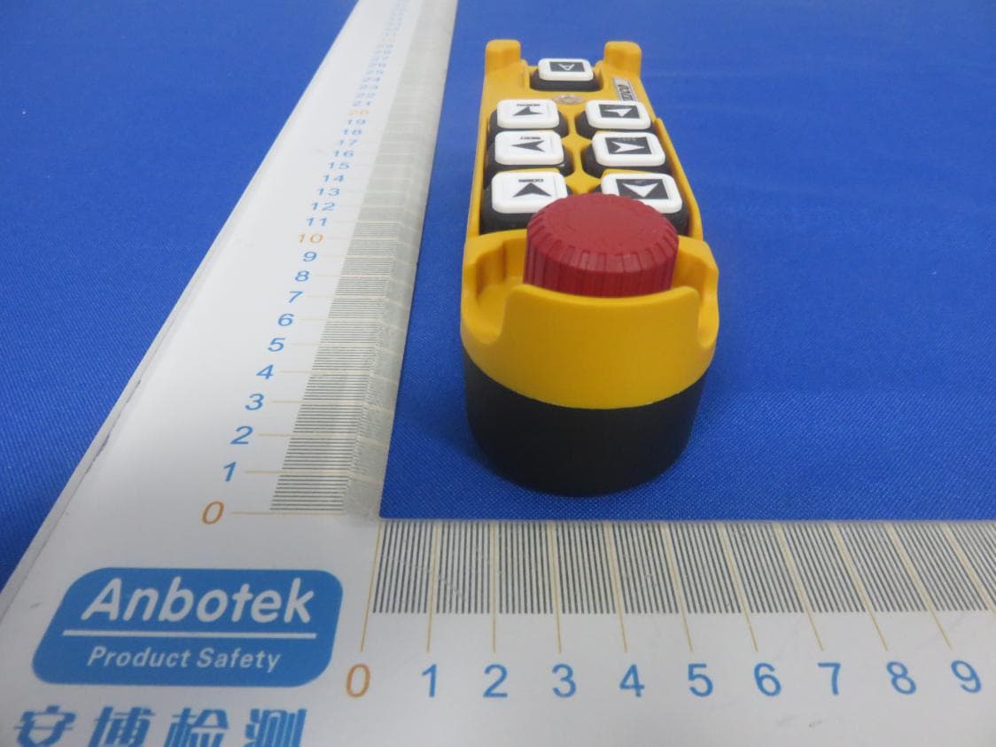
2AVDH-JREMO6K
Jan 08, 2020Industrial wireless remote controller
Equipment Class
DSC - Part 15 Security/Remote Control Transmitter