FCCID.CO- FCC ID Database
HomeCompaniesEquipment ClassesSearch

© 2026 FCC ID Database. All rights reserved.

AboutContactData sourced from FCC public records
  1. Home/
  2. Apricity Code Corporation/
  3. 2AVFOARA-001V3

2AVFOARA-001V3APHW-02A

Apricity Code Corporation
APHW-02A - FCC ID 2AVFOARA-001V3 - Apricity Code Corporation
Click to zoom

Application Details

Equipment Class
DTS - Digital Transmission System
Date of Grant
Feb 08, 2021
Application Purpose
Original Equipment
Date of Application
Feb 08, 2021
Equipment Note
APHW-02A
Frequency Range
2402.00000000 - 2480.00000000
Company
Apricity Code Corporation
Country
United States

Documents & Files

Select a file to view
Users Manual

↗

Cover Letter(s)

↗
↗

External Photos

↗

ID Label/Location Info

↗

Internal Photos

↗

Operational Description

↗
↗

RF Exposure Info

↗

Test Report

↗

Test Setup Photos

↗

Document Text

Text extracted from the exhibit documents filed with the FCC. Open a document above to read the original.

Users Manual

©2020 Apricity Code Inc. ARA Load Control Switch LTE Connected Installation Instructions – Model: APHW-02A 1 Introduction The Apricity ARA Load Control Switch is a utility-connected LTE communication and switch device for energy management of residential hot water heaters. This manual describes the physical installation of the ARA. Installation is straightforward and can be completed by a qualified homeowner but is typically completed by an agent of the electrical utility. The installer should always consult state and local codes to ensure a compliant installation. Once the unit is installed and powered on, it will automatically connect over cellular networks and be available for grid power management. Units are pre-configured by Apricity on a client-by-client basis. 2 Installation Preparation Installation will require, at a minimum, the following tools. Some circumstances may require additional tools depending on the conditions around the existing electrical panel and hot water heater. • Phillips-head and flat-head screwdrivers • Wire strippers • Pliers or Wrenches (for cable clamp/conduit connection) • Recommended: voltage tester or sniffer (to confirm hot water heater is disconnected by circuit breaker panel) This procedure simply describes the steps for connecting the ARA to the hot water heater circuit and is not an introduction to electrical wiring or safety. If you are not confident that you can proceed safely with this work, contact a licensed electrician to complete the installation for you. Installation instructions may vary depending on the configuration of your hot water heater, some adjustments may be required. Installation consists of removing the top plate from the existing water heater junction box, and building the ARA into the circuit with the mains AC power supply connected to the “Line In” terminals, and the water heater load connected to the “Output” terminals. Proceed with the installation as follows: Existing Junction Disassembly 1. Turn off the electricity to the hot water heater by switching the circuit breaker to the “OFF” position. Confirm that there is no voltage at the hot water heater connection before proceeding. 2. Remove the electrical cover plate from the junction box on top of the water heater. Check voltages to confirm that power is disconnected. 3 3. Remove the wire nuts from the wires and sepARAte. The panel-side wires (always on) will connect to “Line In,” and the heater load wires will connect to “Output” 4. Loosen and remove the cable clamp from the junction box cover. Remove the cover plate from the wires and set aside. 5. Unscrew the cover of the Apricity ARA and set the cover aside. 6. Check the length of the existing ground, it will need to pass through both conduit ports on the ARA and return to the heater’s bonding screw or post in the same way as it does without the ARA in place. Provide additional length with a junction inside the ARA if necessary. Mounting the Controller 7. Instructions are provided for mounting the ARA to either the water heater or to the wall. We recommend mounting to the water heater where space permits: Heater Mount: • Remove one washer and one nut from the conduit fitting leaving the closest to the ARA. Ensure the that the nut closest to the ARA is secure. • Mount the cover plate from the water heater onto the conduit fitting at the bottom of the ARA, with the ARA facing into the room. Replace washer and nut, tighten. • Thread the load wires from the hot water heater through the cover plate and the connected hole of the ARA. Place the ARA and cover plate back onto the hot water heater and fasten the cover plate in place using the original screws. o If the cover plate cannot be refastened to the heater with the ARA in place, then install the supplied conduit fitting on the cover plate with the ARA detached, fasten the conduit plate to the hot water heater, and then install the ARA on the plate, with the load wires threaded through the assembly as above. Wall Mount (Alternative): 4 • If there is insufficient space above the hot water heater for the controller, wall mounting must be used. • An additional length of flexible conduit, clamps, and wires are required (not included). • Select a suitable location to mount the controller to the wall, and mount the controller to the wall using the provided mounting holes. • Attach the additional conduit to the bottom of the controller and attach the other end to the junction box cover. Feed hot water heater wires through the conduit (additional wire, including a ground extension, will likely be needed: use code compliant wire for your jurisdiction as necessary). Finally, secure the junction box cover back to hot water heater. 8. Connect the load wires from the water heater to the terminal block labeled “OUTPUT” inside the ARA. Route the wires to the terminal block and trim to length with ¼” of bare wire exposed on the ends. 9. Open the terminal blocks by turning its screws counterclockwise until the screw threads click. Insert the wire into the opening on the side of the terminal block and tighten the screw until snug. Do not over-tighten, or the ARA may be damaged, and the wires may not hold. Terminal blocks accept 10-30 AWG wire. 10. Install the heater’s original cable clamp for the supply wires in the conduit port at the top of the ARA. 11. Thread the supply wires through the Line In conduit port on the ARA, and provide an extension of the ground wire if necessary. The line and neutral wires should be long enough to reach the terminal blocks on the ARA – if not, provide extensions as necessary. Trim, strip, and connect the supply wires to the Line In terminal block on the ARA. a. Note: If it is necessary to preserve line and neutral orientation for the model hot water heater you are working on (i.e. a 120v hot water heater), when the ARA’s relay is closed the two nearest screw posts are connected (lower Line In to upper Output), and the two furthest screw posts are connected …

Text truncated - open the document above for the full version.

Cover Letter(s)

Connect Bend Boston (541) 204-4450 2789 NW Lolo Drive 288 Norfolk Street [email protected] Bend, OR 97703 Suite 3A www.apricitycode.com Cambridge, MA 02139 Date: 19 November 2020 Federal Communications Commission Authorization and Evaluation Decision 7435 Oakland Mills Road Columbia, Maryland 21046 Re: Cover Letter for FCC Application FCC ID: 2AVFOARA-001V3 We hereby request original FCC certification under rule part 15.247 for “ARA Load Control Switch”, model number APHW-02A. This device contains an FCC Certified LTE CAT-M1 radio module (FCC ID: 2ANPO00NRF9160), an optional FCC Certified Wi-Fi 802.11b/g/n radio module (FCC ID: 2AC7Z- ESPWROOM02D), and a Bluetooth 5 radio transmitter. The radios do not transmit simultaneously. The Bluetooth radio has been tested for intentional radiation by Element Materials Technology, and the unit has been tested for unintentional radiation at the same facility. Sincerely, Jacob Betcher COO – Apricity Code Corporation

Cover Letter(s)

Connect Bend Boston (541) 204-4450 2789 NW Lolo Drive 288 Norfolk Street [email protected] Bend, OR 97703 Suite 3A www.apricitycode.com Cambridge, MA 02139 Date: 6 November 2020 Federal Communications Commission Authorization and Evaluation Division 7435 Oakland Mills Road Columbia, Maryland 21046 Re: Request for confidentiality FCC ID: 2AVFOARA-001V3 To whom it may concern, We hereby respectfully request that under the provision of 47 CFR 0.459 and 0.457(d) the documents listed below and attached with this application for certification be provided with confidential status. Type of Confidentiality Requested Exhibit Short Term Permanent Block Diagrams Short Term Permanent Internal Photos Short Term Permanent Operation Description/Theory of Operation Short Term Permanent Schematics Short Term Permanent User’s Manual Any exhibit / information for which we have requested confidentiality, but which may not be accorded such treatment by the FCC, should be returned to us. The documents listed above contain trade secrets that are treated as confidential by us. Substantial competitive harm to us could result should they be made available to the public. Sincerely, Jacob Betcher COO

External Photos

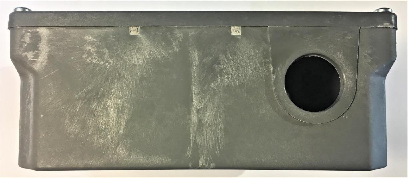
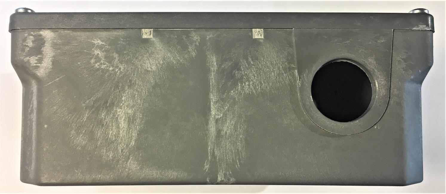
Connect Bend Boston (541) 204-4450 2789 NW Lolo Drive 288 Norfolk Street [email protected] Bend, OR 97703 Suite 3A www.apricitycode.com Cambridge, MA 02139 External Photos | FCC ID: 2AVFOARA-001V3 | IC: 25756-ARA001V3 Front Back Connect Bend Boston (541) 204-4450 2789 NW Lolo Drive 288 Norfolk Street [email protected] Bend, OR 97703 Suite 3A www.apricitycode.com Cambridge, MA 02139 Top Bottom Connect Bend Boston (541) 204-4450 2789 NW Lolo Drive 288 Norfolk Street [email protected] Bend, OR 97703 Suite 3A www.apricitycode.com Cambridge, MA 02139 Right Side Left Side

ID Label/Location Info

Connect Bend Boston (541) 204-4450 2789 NW Lolo Drive 288 Norfolk Street [email protected] Bend, OR 97703 Suite 3A www.apricitycode.com Cambridge, MA 02139 Label and Location | FCC ID: 2AVFOARA-001V3 | IC: 25756-ARA001V3 Label Location Connect Bend Boston (541) 204-4450 2789 NW Lolo Drive 288 Norfolk Street [email protected] Bend, OR 97703 Suite 3A www.apricitycode.com Cambridge, MA 02139 Label (without WiFi module) Label (with WiFi module)

Internal Photos

Internal Photos | FCC ID: 2AVFOARA-001V3 | IC: 25756-ARA001V3 Connect Bend Boston (541) 204-4450 2789 NW Lolo Drive 288 Norfolk Street [email protected] Bend, OR 97703 Suite 3A www.apricitycode.com Cambridge, MA 02139 LTE Antenna: ANT-LTE-CER-T BT Antenna: 2450AT18D0100E Internal Photos | FCC ID: 2AVFOARA-001V3 | IC: 25756-ARA001V3 Connect Bend Boston (541) 204-4450 2789 NW Lolo Drive 288 Norfolk Street [email protected] Bend, OR 97703 Suite 3A www.apricitycode.com Cambridge, MA 02139 Internal Photos | FCC ID: 2AVFOARA-001V3 | IC: 25756-ARA001V3 Connect Bend Boston (541) 204-4450 2789 NW Lolo Drive 288 Norfolk Street [email protected] Bend, OR 97703 Suite 3A www.apricitycode.com Cambridge, MA 02139 WITHOUT SHIELD Internal Photos | FCC ID: 2AVFOARA-001V3 | IC: 25756-ARA001V3 Connect Bend Boston (541) 204-4450 2789 NW Lolo Drive 288 Norfolk Street [email protected] Bend, OR 97703 Suite 3A www.apricitycode.com Cambridge, MA 02139 WITH SHIELD (ACCESS LEVEL OF AN ELECTRICIAN/INSTALLER)

Operational Description

P/N 2450AT18D0100 Detail Specification: Page 1 of 7 ¹Efficiency measured on Johanson's evaluation board PN 2450AT18D0100-EB1SMA No. ±± 1 ±± 2 ±± 3 4 ±± Function 1: Antenna fed from left Function 2: Antenna fed from right https://www.johansontechnology.com 4001 Calle Tecate • Camarillo, CA 93012 • TEL 805.389.1166 FAX 805.389.1821 Ver. 4.2 2019 Johanson Technology, Inc. All Rights Reserved 2.45 GHz SMD Antenna, EIA 1210, Detuning resilient, Edge Mount Design 10 min. +5 to +35°C Humidity 45 - 75% RH Radiated Efficiency¹ 72% Return Loss (dB) Impedance (Ω) Input Power (W) 50 2 max. (CW) mm e.g. 2450AT18D0100E e.g. 2450AT18D0100SSuffix = S Part Number Explanation Function 1Function 2 Terminal Configuration FEED GND GND GND GND GND GND FEED b 0.0200.500.20.008 a 0.0120.30 +0.1 / -0.2+0.004 / -0.008 T 0.0471.200.10.004 3.200.2 W 0.0630.0081.600.2 Johanson Technology, Inc. reserves the right to make design changes without notice. All sales are subject to Johanson Technology, Inc. terms and conditions. e.g. 2450AT18D0100(E or S)100% Tin Packing Style Evaluation Board 2450AT18D0100-EB1SMA Bulk (loose) T&R Suffix = E or S Suffix = E P/N Suffix Mechanical Dimensions In L 0.1260.008 Operating Temperature -40 to +125°C Recommended Storage Conditions and Period for unused T&R Product 18 months max. High Frequency Ceramic Solutions Part Number 3/26/2019 Peak Gain (dBi) Let us help you with the antenna design, optimization, and tuning! 2450AT18D0100 2.4 - 2.48 1.5 dBi General Specifications Frequency (GHz) Average Gain (dBi) -1.0 dBi 1 2 4 3 b T L a w b P/N 2450AT18D0100 Detail Specification: Page 2 of 7 https://www.johansontechnology.com 4001 Calle Tecate • Camarillo, CA 93012 • TEL 805.389.1166 FAX 805.389.1821 Ver. 4.2 2019 Johanson Technology, Inc. All Rights Reserved High Frequency Ceramic Solutions 3/26/2019 Mounting Considerations 1: Evaluation Board (Standard Layout) Johanson Technology, Inc. reserves the right to make design changes without notice. All sales are subject to Johanson Technology, Inc. terms and conditions. 2.45 GHz SMD Antenna, EIA 1210, Detuning resilient, Edge Mount Design To order a pre‐tuned 50Ω EVB with a female SMA connector click here: www.johansontechnology.com/request‐a‐sample Reference p/n: 2450AT18D0100‐EB1SMA Units in mm Ground Vias Feeding Line Ground clearance 40mm 20mm Matching Circuits Measured radiated efficiency of 2450AT18D0100 on this evaluation board is 72% 1.02.01.0 0.6 0.7 0.6 4.1 4.0 0 Ohm Matching Circuits No ground, metal PCB layers, or other metallic components like batteries directly underneath antenna! Ground Ground Ground 6.0 Land Solder Resist 50Ω Trace (Grounded CPWG type is preferred) GND Vias P/N 2450AT18D0100 Detail Specification: Page 3 of 7 https://www.johansontechnology.com 4001 Calle Tecate • Camarillo, CA 93012 • TEL 805.389.1166 FAX 805.389.1821 Ver. 4.2 2019 Johanson Technology, Inc. All Rights Reserved High Frequency Ceramic Solutions 3/26/2019 Mounting Considerations 1: Electrical Performance @25°C Johanson Technology, Inc. reserves the right to make design changes without notice. All sales are subject to Johanson Technology, Inc. terms and conditions. 2.45 GHz SMD Antenna, EIA 1210, Detuning resilient, Edge Mount Design Measured Return Loss Would you like the antenna layout? Have antenna tuning issues? Please contact us if you have any questions regarding the implementation of this antenna in your PCB's layout. We'll be happy to guide you to maximize the antenna's performance. Contact our applications engineers at: www.johansontechnology.com/ask-a-question 2.22.42.62.82.03.0 -20 -10 -30 0 freq, GHz dB(S(1,1)) m1 m2 m3 m1 freq= dB(S(1,1))=-13.935 2.400GHz m2 freq= dB(S(1,1))=-14.774 2.500GHz m3 freq= dB(S(1,1))=-24.894 2.450GHz P/N 2450AT18D0100 Detail Specification: Page 4 of 7 https://www.johansontechnology.com 4001 Calle Tecate • Camarillo, CA 93012 • TEL 805.389.1166 FAX 805.389.1821 Ver. 4.2 2019 Johanson Technology, Inc. All Rights Reserved High Frequency Ceramic Solutions 3/26/2019 Mounting Considerations 1: Typical 2D radiation patterns @ 2.44GHz Johanson Technology, Inc. reserves the right to make design changes without notice. All sales are subject to Johanson Technology, Inc. terms and conditions. 2.45 GHz SMD Antenna, EIA 1210, Detuning resilient, Edge Mount Design YZ‐plane XZ‐plane XY‐plane θ +Z (θ= 0°) +Y (θ= 90°) -Y -Z θ +Z (θ= 0°) +X (θ= 90°) -X -Z φ +X (φ= 0°) -X +Y (φ= 90°) -Y +Z -Z +Y -Y +Z -Z +X-X +X -X +Y -Y P/N 2450AT18D0100 Detail Specification: Page 5 of 7 https://www.johansontechnology.com 4001 Calle Tecate • Camarillo, CA 93012 • TEL 805.389.1166 FAX 805.389.1821 Ver. 4.2 2019 Johanson Technology, Inc. All Rights Reserved Johanson Technology, Inc. reserves the right to make design changes without notice. All sales are subject to Johanson Technology, Inc. terms and conditions. Mounting Considerations 3: "Thin edge" application on circular PCB Mounting Considerations 2: Small Clearance or "Thin edge" Applications* High Frequency Ceramic Solutions 3/26/2019 2.45 GHz SMD Antenna, EIA 1210, Detuning resilient, Edge Mount Design Units in mm * 1.02.01.0 0.6 0.7 0.6 1.5 8.0 Reserve for Pi-matching circuit Ground 0.6 2.8 0.63.4 Blue Area = LCD/Metal/CAN/GND/Battery etc. 3.4 Land Solder Resist GND clearance *Evaluation board not available *Evaluation board not available 50Ω Trace (Grounded CPWG type is preferred) No ground, metal PCB layers, or other metallic components like batteries and displays directly underneath antenna! Ground Want the layout file of this example? Send us a message at: www.johansontechnology.com/ask‐a‐question P/N 2450AT18D0100 Detail Specification: Page 6 of 7 https://www.johansontechnology.com 4001 Calle Tecate • Camarillo, CA 93012 • TEL 805.389.1166 FAX 805.389.1821 Ver. 4.2 2019 Johanson Technology, Inc. All Rights Reserved Johanson Technology, Inc. reserves the right to make design changes without notice. All sales are subject to Johanson Technology, Inc. terms and conditions. High Frequency Ce…

Text truncated - open the document above for the full version.

Operational Description

Connect Bend Boston (541) 204-4450 2789 NW Lolo Drive 288 Norfolk Street [email protected] Bend, OR 97703 Suite 3A www.apricitycode.com Cambridge, MA 02139 Antenna Information | FCC ID: 2AVFOARA-001V3 | IC: 25756-ARA001V3 A list of antennas to be used with the transmitter. include manufacturer, model number, gain (dbi) and description (e.g.dipole, yagi, patch, etc.) BT Antenna: Johanson Technology, 2450AT18D0100E, 1.5dBi, Chip LTE Antenna: Linx Technologies, ANT-LTE-CER-T, 4.0dBi, Chip Wi-Fi Antenna: Expressif, on-module PCB trace antenna. For FCC Part 15 transmitters, describe compliance with FCC 15.203 Snippet of 15.203: “An intentional radiator shall be designed to ensure that no antenna other than that furnished by the responsible party shall be used with the device. The use of a permanently attached antenna or of an antenna that uses a unique coupling to the intentional radiator shall be considered sufficient to comply with the provisions of this section.” The antennas are located inside the product enclosure and are not designed to be user replaceable. No external access to the antennas or antenna connectors is provided. For transmitters below 30 MHz, instead of the gain, please provide the dimensions of the loop antenna and / or a ruler in the photograph of the loop. The size of the loop, the dimensions, and the number of turns should be documented. N/A Please see next page for detailed antenna photos. Connect Bend Boston (541) 204-4450 2789 NW Lolo Drive 288 Norfolk Street [email protected] Bend, OR 97703 Suite 3A www.apricitycode.com Cambridge, MA 02139 Antenna Information | FCC ID: 2AVFOARA-001V3 | IC: 25756-ARA001V3 BT ANTENNA LTE ANTENNA

RF Exposure Info

This report must not be used to claim product certification, approval, or endorsement by NVLAP, NIST, or any agency of the U.S. Government. This Report shall not be reproduced, except in full without written approval of the laboratory. EAR-Controlled Data - This document contains technical data whose export and reexport/retransfer is subject to control by the U.S. Department of Commerce under the Export Administration Act and the Export Administration Regulations. The Department of Commerce’s prior written approval may be required for the export or re- export/retransfer of such technical data to any foreign person, foreign entity or foreign organization whether in the United States or abroad. More: https://www.bis.doc.gov/index.php/forms-documents/regulations-docs/14-commerce-country-chart/fileT Apricity Code APHW-02A FCC 2.1091:2021 802.11 Bluetooth LE Cellular Report: APRI0011.3 NVLAP Lab Code: 200630-0 CERTIFICATE OF EVALUATION 2018-09-14 Product compliance is the responsibility of the client; therefore, the tests and equipment modes of operation represented in this report were agreed upon by the client, prior to testing. The results of this test pertain only to the sample(s) tested. The specific description is noted in each of the individual sections of the test report supporting this certificate of test. This report reflects only those tests from the referenced standards shown in the certificate of test. It does not include inspection or verification of labels, identification, marking or user information. As indicated in the Statement of Work sent with the quotation, Element’s standard process is to always use the latest published version of the test methods even when earlier versions are cited in the test specification. Issuance of a purchase order was de facto acceptance of this approach. Otherwise, the client would have advised Element in writing of the specific version of the test methods they wanted applied to the subject testing Last Date of Evaluation: Thursday, January 14, 2021 Apricity Code EUT: APHW-02A RF Exposure Evaluation Standards Specification Method FCC 2.1091:2021 FCC 447498 D01 General RF Exposure Guidance v06 Results Method Clause Description Applied Results Comments 7.1 Maximum Permissible Exposure Yes Pass None Deviations From Evaluation Standards None Approved By: Donald Facteau, Process Architect Report No. APRI0011.3EAR-Controlled Data2/10 REVISION HISTORY 2018.07.17 Revision Number Description Date (yyyy-mm-dd) Page Number 00 None Report No. APRI0011.3EAR-Controlled Data3/10 ACCREDITATIONS AND AUTHORIZATIONS 2019.03.08 United States FCC - Designated by the FCC as a Telecommunications Certification Body (TCB). Certification chambers, Open Area Test Sites, and conducted measurement facilities are listed with the FCC. A2LA - Accredited by A2LA to ISO / IEC 17065 as a product certifier. This allows Element to certify transmitters to FCC and IC specifications. NVLAP - Each laboratory is accredited by NVLAP to ISO 17025 Canada ISED - Recognized by Innovation, Science and Economic Development Canada as a Certification Body (CB) and as a CAB for the acceptance of test data. European Union European Commission – Within Element, we have a EU Notified Body validated for the EMCD and RED Directives. Australia/New Zealand ACMA - Recognized by ACMA as a CAB for the acceptance of test data. Korea MSIT / RRA - Recognized by KCC’s RRA as a CAB for the acceptance of test data. Japan VCCI - Associate Member of the VCCI. Conducted and radiated measurement facilities are registered. Taiwan BSMI – Recognized by BSMI as a CAB for the acceptance of test data. NCC - Recognized by NCC as a CAB for the acceptance of test data. Singapore IDA – Recognized by IDA as a CAB for the acceptance of test data. Israel MOC – Recognized by MOC as a CAB for the acceptance of test data. Hong Kong OFCA – Recognized by OFCA as a CAB for the acceptance of test data. Vietnam MIC – Recognized by MIC as a CAB for the acceptance of test data. SCOPE For details on the Scopes of our Accreditations, please visit: https://www.nwemc.com/emc-testing-accreditations Report No. APRI0011.3EAR-Controlled Data4/10 FACILITIES 2020.12.15 California Labs OC01-17 41 Tesla Irvine, CA 92618 (949) 861-8918 Minnesota Labs MN01-11 9349 W Broadway Ave. Brooklyn Park, MN 55445 (612)-638-5136 Oregon Labs EV01-12 6775 NE Evergreen Pkwy #400 Hillsboro, OR 97124 (503) 844-4066 Texas Labs TX01-09 3801 E Plano Pkwy Plano, TX 75074 (469) 304-5255 Washington Labs NC01-05 19201 120 th Ave NE Bothell, WA 98011 (425)984-6600 NVLAP NVLAP Lab Code: 200676-0 NVLAP Lab Code: 200881-0 NVLAP Lab Code: 200630-0 NVLAP Lab Code:201049-0 NVLAP Lab Code: 200629-0 Innovation, Science and Economic Development Canada 2834B-1, 2834B-3 2834E-1, 2834E-3 2834D-1 2834G-1 2834F-1 BSMI SL2-IN-E-1154R SL2-IN-E-1152R SL2-IN-E-1017 SL2-IN-E-1158R SL2-IN-E-1153R VCCI A-0029 A-0109 A-0108 A-0201 A-0110 Recognized Phase I CAB for ISED, ACMA, BSMI, IDA, KCC/RRA, MIC, MOC, NCC, OFCA US0158 US0175 US0017 US0191 US0157 Report No. APRI0011.3EAR-Controlled Data5/10 PRODUCT DESCRIPTION 2018-07-17 Client and Equipment Under Evaluation Information Company Name: Apricity Code Address: 2783 NW Lolo Dr., Suite 130 City, State, Zip: Bend, OR 97702 Evaluation Requested By: Gavin Lund EUT: APHW-02A Date of Evaluation: Thursday, January 14, 2021 Information Provided by the Party Requesting the Evaluation Functional Description of the Equipment: The APHW-02A is a controller for water heaters or other home appliances for energy demand management. It contains a Bluetooth LE radio, an 802.11 module (FCC ID: 2AC7Z-ESPWROOM02D) and a cellular module (FCC ID: 2ANPO00NRF916). Each radio includes a separate amplifier and antenna. The radios are not designed to transmit simultaneously. Objective: To demonstrate compliance with FCC requirements for RF exposure for 2.1091 mobile/fixed devices Report No. APRI0011.3EAR-Controlled Data6/10 RF Exposure Condition 2018-07-17 The following RF Exposu…

Text truncated - open the document above for the full version.

Test Report

This report must not be used to claim product certification, approval, or endorsement by NVLAP, NIST, or any agency of the U.S. Government. This Report shall not be reproduced, except in full without written approval of the laboratory. EAR-Controlled Data - This document contains technical data whose export and reexport/retransfer is subject to control by the U.S. Department of Commerce under the Export Administration Act and the Export Administration Regulations. The Department of Commerce’s prior written approval may be required for the export or re- export/retransfer of such technical data to any foreign person, foreign entity or foreign organization whether in the United States or abroad. Apricity Code Water Heater Controller FCC 15.247:2020 Bluetooth LE Radio Report: APRI0011.1, Issue Date: December 22, 2020 NVLAP LAB CODE: 200630-0 CERTIFICATE OF TEST 2018-09-14 Product compliance is the responsibility of the client; therefore, the tests and equipment modes of operation represented in this report were agreed upon by the client, prior to testing. The results of this test pertain only to the sample(s) tested. The specific description is noted in each of the individual sections of the test report supporting this certificate of test. This report reflects only those tests from the referenced standards shown in the certificate of test. It does not include inspection or verification of labels, identification, marking or user information. As indicated in the Statement of Work sent with the quotation, Element’s standard process is to always use the latest published version of the test methods even when earlier versions are cited in the test specification. Issuance of a purchase order was de facto acceptance of this approach. Otherwise, the client would have advised Element in writing of the specific version of the test methods they wanted applied to the subject testing. Last Date of Test: November 13, 2020 Apricity Code EUT: Water Heater Controller Radio Equipment Testing Standards Specification Method FCC 15.207:2020 ANSI C63.10:2013 FCC 15.247:2020 ANSI C63.10:2013, KDB 558074 Results Method Clause Test Description Applied Results Comments 6.2 Powerline Conducted Emissions Yes Pass 6.5, 6.6, 11.12.1, 11.13.2 Spurious Radiated Emissions Yes Pass 11.6 Duty Cycle Yes Pass 11.8.2 Occupied Bandwidth Yes Pass 11.9.1.1 Output Power Yes Pass 11.9.1.1 Equivalent Isotropic Radiated Power Yes Pass 11.10.2 Power Spectral Density Yes Pass 11.11 Band Edge Compliance Yes Pass 11.11 Spurious Conducted Emissions Yes Pass Deviations From Test Standards None Approved By: Kyle Holgate, Operations Manager Report No. APRI0011.1EAR-Controlled Data2/49 REVISION HISTORY 2018.07.17 Revision Number Description Date (yyyy-mm-dd) Page Number 00 None Report No. APRI0011.1EAR-Controlled Data3/49 ACCREDITATIONS AND AUTHORIZATIONS 2019.03.08 United States FCC - Designated by the FCC as a Telecommunications Certification Body (TCB). Certification chambers, Open Area Test Sites, and conducted measurement facilities are listed with the FCC. A2LA - Accredited by A2LA to ISO / IEC 17065 as a product certifier. This allows Element to certify transmitters to FCC and IC specifications. NVLAP - Each laboratory is accredited by NVLAP to ISO 17025 Canada ISED - Recognized by Innovation, Science and Economic Development Canada as a Certification Body (CB) and as a CAB for the acceptance of test data. European Union European Commission – Within Element, we have a EU Notified Body validated for the EMCD and RED Directives. Australia/New Zealand ACMA - Recognized by ACMA as a CAB for the acceptance of test data. Korea MSIT / RRA - Recognized by KCC’s RRA as a CAB for the acceptance of test data. Japan VCCI - Associate Member of the VCCI. Conducted and radiated measurement facilities are registered. Taiwan BSMI – Recognized by BSMI as a CAB for the acceptance of test data. NCC - Recognized by NCC as a CAB for the acceptance of test data. Singapore IDA – Recognized by IDA as a CAB for the acceptance of test data. Israel MOC – Recognized by MOC as a CAB for the acceptance of test data. Hong Kong OFCA – Recognized by OFCA as a CAB for the acceptance of test data. Vietnam MIC – Recognized by MIC as a CAB for the acceptance of test data. SCOPE For details on the Scopes of our Accreditations, please visit: https://www.nwemc.com/emc-testing-accreditations Report No. APRI0011.1EAR-Controlled Data4/49 FACILITIES 2019.03.08 California Labs OC01-17 41 Tesla Irvine, CA 92618 (949) 861-8918 Minnesota Labs MN01-10 9349 W Broadway Ave. Brooklyn Park, MN 55445 (612)-638-5136 Oregon Labs EV01-12 6775 NE Evergreen Pkwy #400 Hillsboro, OR 97124 (503) 844-4066 Texas Labs TX01-09 3801 E Plano Pkwy Plano, TX 75074 (469) 304-5255 Washington Labs NC01-05 19201 120 th Ave NE Bothell, WA 98011 (425)984-6600 NVLAP NVLAP Lab Code: 200676-0 NVLAP Lab Code: 200881-0 NVLAP Lab Code: 200630-0 NVLAP Lab Code:201049-0 NVLAP Lab Code: 200629-0 Innovation, Science and Economic Development Canada 2834B-1, 2834B-3 2834E-1, 2834E-3 2834D-1 2834G-1 2834F-1 BSMI SL2-IN-E-1154R SL2-IN-E-1152R SL2-IN-E-1017 SL2-IN-E-1158R SL2-IN-E-1153R VCCI A-0029 A-0109 A-0108 A-0201 A-0110 Recognized Phase I CAB for ISED, ACMA, BSMI, IDA, KCC/RRA, MIC, MOC, NCC, OFCA US0158 US0175 US0017 US0191 US0157 Report No. APRI0011.1EAR-Controlled Data5/49 MEASUREMENT UNCERTAINTY TMU.2015.07.10 Measurement Uncertainty When a measurement is made, the result will be different from the true or theoretically correct value. The difference is the result of tolerances in the measurement system that cannot be completely eliminated. To the extent that technology allows us, it has been our aim to minimize this error. Measurement uncertainty is a statistical expression of measurement error qualified by a probability distribution. A measurement uncertainty estimation has been performed for each test per our internal quality document QM205.4.6. The estimation is used to compare the measured result with its "true" or…

Text truncated - open the document above for the full version.

Test Setup Photos

POWERLINE CONDUCTED EMISSIONS WTD.2020.03.25.0 , POWERLINE CONDU…

Text truncated - open the document above for the full version.

Contact Information

Applicant

Jacob Betcher(COO)
[email protected]5412044422Fax: 5412044450

Test Firm

Element Materials TechnologyRenee Walker
[email protected]503-844-4066Fax: 503-844-3826

Technical Specifications

#Rule PartsFrequency RangePower Output
115C2.40 GHz - 2.48 GHz500.00 µW
Confidentiality
Long Term
Grant Notes
Output power listed is conducted. The antenna(s) used for the transmitter must be installed to provide a separation distance of at least 20 cm from all person and must not be collocated or operating in conjunction with any other antenna or transmitter, except in accordance with FCC multi-transmitter product procedures.

Other Applications from Apricity Code Corporation

APHW-01A - FCC ID 2AVFOARA-001V2 - Apricity Code Corporation
2AVFOARA-001V2

APHW-01A

Feb 12, 2020

Equipment Class

DTS - Digital Transmission System