2AVFRLED-DC12Remote Controller
Oriental Recreational Products(Shanghai)Co.,Ltd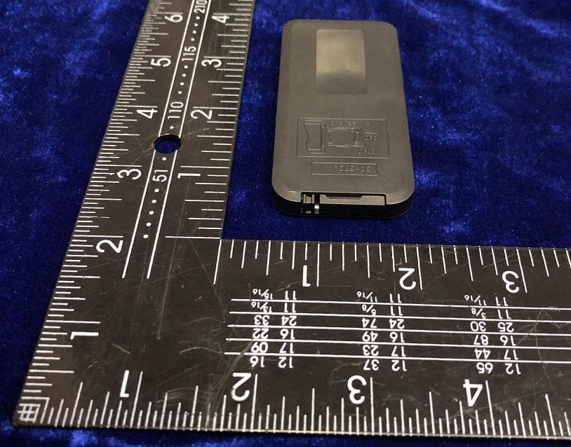
Click to zoom
Application Details
- Equipment Class
- DSC - Part 15 Security/Remote Control Transmitter
- Date of Grant
- Dec 28, 2020
- Application Purpose
- Original Equipment
- Date of Application
- Dec 28, 2020
- Equipment Note
- Remote Controller
- Frequency Range
- 433.92000000 - 433.92000000
- Country
- China
Documents & Files
Document Text
Text extracted from the exhibit documents filed with the FCC. Open a document above to read the original.
Users Manual
LEDStrip with remote control www.the-mspa.com ENJOY THEMOMENT OWNER’SMANUAL Congratulations on your purchase of MSpa. We are confident that you will enjoy many benefits of using MSpa with the LED strip for years to come. Carefully and thoroughly read this manual before using the product for the firsttime. For your own safety and that of your equipment, make sure to take the following precautions. Failure to follow the warning notices and instruction may result in property damage, serious injury ordeath. WARNING PRODUCTCONTENTS a) 1 X LED strip b) 1 X AC poweradapter Picture for reference only. The actual adapters may vary for different regionalstandards. Power connectionend C) 1 X remote control SAFETYPRECAUTIONS • Do not pull or break the light strip with excessiveforce when install or disassemblethe LED strip to or from the spa pool. • Only use the MSpa AC power adapter to connect the LED strip. • Be aware of the LED strip chip is not exchangeable or removable. • Do not operate the LED strip or connect to the power if the package isunpacked. • Be aware of the linear LED strip can only be operated individually. Do not connect the strip with other LEDstrip. • It is recommended to keep the original package or user’smanual. • The external flexible cable or cord of this luminaire cannot be replaced; if the cord is damaged, the LED strip shall be destroyed. LED STRIP MODEL&SPECIFICATIONS ItemModelLength(m)LED Chips(pcs) LED Strip forD-AU04LED - 4DC12R5150 LED Strip forU-AU061LED - 6DC12R5.7171 Power supply: DC12V, 18W (for LED -4DC12R ), 22W (forLED -6DC12R. ) IP Rating: IP65 ; Do not put the LED strip intowater Lighting Mode: : Colors - Green, blue, lime, white, cyan and purple. Changing every five to six seconds.(for LED- 4DC12R / LED -6DC12R) INSTALLATION 1. Take out the LED strip from the package box, spread itgently. 2. Refer to your MSpa User’s Manual for spa inflation. Assemble the LED strip onto spa bottom after the spa pool is properlyinflated. 3. Put the spa pool up side down. Make sure the installation location must be free of sharp objects or debris. It is recommended to place a ground mat to protect the spa tub before installation. Connect the LED strip (End point) to the spa bottom beside the control box, either clockwise or counterclockwise isgood. 4. Find the PVC connecting channels on the spa pool bottom to secure the LED strip. Starting from either side of the control box, take the end point of the LED strip, make it get trough the PVC channel one by one. Ensure the strip light front side (with the chips) face to the spa poolbottom. Please note the Power connection end of the LED strip can not be passed through the PVCchannel. To help reduce the friction between the LED strip and PVC channel during assembly or disassembly, please gently spray the LED strip with some water before install or uninstall the LEDstrip. 5. During the installation, make sure the LED strip pass through each PVC channel completely and correctly before to the next PVC channel, no twist or bump. Never pull the strip with excessive force, which will cause damage to the strip and void the warranty. Place the LED strip on the spa bottom and chips face inside the spa for best lightingeffect. 6. After passing through all the PVC connection channels smoothly, the LED strip makes an even circle at the spa tub bottom. Now turn the spa tub over and place it on the floor gently. Find the Power connection end of LED strip bottom, and then connect it to the AC power adapter, plug into the outlet and check if the LED strip operates normally. Connect LED strip to the ACadapter PVC Channel Front side of the strip Choose either side ofthe control box to start connecting the LED strip Front side face to thespa bottom Remote Controller 1 2 3 4 5 6 7 8 9 10 11 Dynamicmode22 modes Static Color20 colors PWM Grade256 levels BrightnessGrade5 levels Speed Grade10 levels Demo modeYes Direct Color SelectYes Output Color Switchable Yes, 6 options Working VoltageDC 5~24V Modulation Type Antenna type and Gain ASK PCB antenna,0dBi Remote frequency433.92MHZ Remote distance>15m at open area SPECIFICATIONS FUNCTIONALITY 1. Turn On / Standby Press the button to turn on the light strip or switch to standby mode. When being powered on, the light strip will automatically turn on and restore to the previous state. 2/9. Dynamic Mode Adjust Switch to dynamic mode from static color, or switch between dynamic modes. 3/10. Dynamic Speed Adjust Adjust the dynamic playing speed. The light will switch to dynamic mode If press this button at static color mode. 4/5. Static Color Adjust Switch to static color mode from dynamic mode, or switch between static colors. 6. Direct Color Select Select static colors directly. When press the specific color button, light strip will play the same static color. The direct colors are included in “COLOR+” and “COLOR- “operation. 7/8. Brightness Adjust Adjust static color brightness. The light will switch to static color mode If press this button at dynamic mode. 11. Demo Mode Press this button will switch to Demo mode. At demo mode, it plays 17 dynamic modes in loop, each mode repeats 3 times. OPERATION Using Remote Controller Pull out the battery insulating tape before using. Install button batteries (not included). Pairing New Remote The light strip and remote controller from the same set have already been paired. To pair light strip to additional or new remote controller, please follow the step below: 1. Unplug the light strip. Plug it back after 5 seconds. 2. Press “SPEED+” and “SPEED-” at the same time and hold for 5 seconds. The pairing is completed. Switch Color Sequence If the direct color button doesn't match output LED light, follow below steps to adjust the light sequences: 1. Unplug the light strip. Plug it back after 5 seconds. 2. Press RED and BLUE button together and hold for 5 seconds. With this operation, the output light sequence will switch between 6 possible combinations. ORIENTAL RECREATIONAL …
Text truncated - open the document above for the full version.
External Photos
FCC ID: 2AVFRLED-DC12 IC: 26710-LEDDC12 External Picture FCC ID: 2AVFRLED-DC12 IC: 26710-LEDDC12
ID Label/Location Info
Label & Label Location Label
Internal Photos
FCC ID: 2AVFRLED-DC12 IC: 26710-LEDDC12 Internal Picture FCC ID: 2AVFRLED-DC12 IC: 26710-LEDDC12 Antenna
Test Report
Oriental Recreational Products (shanghai) Co., Ltd. RF TEST REPORT Report Type: FCC Part 15.231 & ISED RSS-210 RF report Model: WM-RF17 REPORT NUMBER: 200901952SHA-001 ISSUE DATE: Nov 18, 2020 DOCUMENT CONTROL NUMBER: TTRF15.231_V1 © 2018 Intertek Intertek Testing Services Shanghai Building No.86, 1198 Qinzhou Road (North) Caohejing Development Zone Shanghai 200233, China Telephone: 86 21 6127 8200 www.intertek.com TEST REPORT This report is for the exclusive use of Intertek's Client and is provided pursuant to the agreement between Intertek and its Client. Intertek's responsibility and liability are limited to the terms and conditions of the agreement. Intertek assumes no liability to any party, other than to the Client in accordance with the agreement, for any loss, expense or damage occasioned by the use of this report. Only the Client is authorized to permit copying or distribution of this report and then only in its entirety. Any use of the Intertek name or one of its marks for the sale or advertisement of the tested material, product or service must first be approved in writing by Intertek. The observations and test results in this report are relevant only to the sample tested. This report by itself does not imply that the material, product, or service is or has ever been under an Intertek certification program. TTRF15.231_V1 © 2018 Intertek Page 2 of 29 Report no.: 200901952SHA-001 Applicant: Oriental Recreational Products (Shanghai) Co., Ltd. No 1699 DaYe Road WuQiao FengXian ShangHai P. R. China Manufacturer: Same as applicant Manufacturing site: Same as applicant FCC ID: 2AVFRLED-DC12 IC: 26710-LEDDC12 SUMMARY: The equipment complies with the requirements according to the following standard(s) or Specification: 47CFR Part 15 (2019): Radio Frequency Devices (Subpart C) ANSI C63.10 (2013): American National Standard of Procedures for Compliance Testing of Unlicensed Wireless Devices RSS-210 Issue 10 (December 2019): Licence-exempt Radio Apparatus (All Frequency Bands): Category I Equipment RSS-Gen Issue 5 (April 2018): General Requirements for Compliance of Radio Apparatus PREPARED BY: REVIEWED BY: Project Engineer Stephanie Zhang Reviewer Wakeyou Wang Report No.: 200901952SHA-001 TEST REPORT TTRF15.231_V1 © 2018 Intertek Page 3 of 29 Content REVISION HISTORY................................................................................................................................................ 4 MEASUREMENT RESULT SUMMARY ..................................................................................................................... 5 1 GENERAL INFORMATION ............................................................................................................................. 6 1.1 DESCRIPTION OF EQUIPMENT UNDER TEST (EUT) ..................................................................................................... 6 1.2 TECHNICAL SPECIFICATION .................................................................................................................................... 6 1.3 DESCRIPTION OF TEST FACILITY .............................................................................................................................. 7 2 TEST SPECIFICATIONS ................................................................................................................................... 8 2.1 STANDARDS OR SPECIFICATION ............................................................................................................................... 8 2.2 MODE OF OPERATION DURING THE TEST ................................................................................................................... 8 2.3 TEST SOFTWARE LIST ............................................................................................................................................ 8 2.4 TEST PERIPHERALS LIST ......................................................................................................................................... 8 2.5 TEST ENVIRONMENT CONDITION: ............................................................................................................................ 9 2.6 INSTRUMENT LIST .............................................................................................................................................. 10 2.7 MEASUREMENT UNCERTAINTY ............................................................................................................................. 11 3 FUNDAMENTAL & SPURIOUS EMISSION & RESTRICT BAND RADIATED EMISSION ...................................... 12 3.1 LIMIT .............................................................................................................................................................. 12 3.2 MEASUREMENT PROCEDURE ............................................................................................................................... 13 3.3 TEST CONFIGURATION ........................................................................................................................................ 14 3.4 TEST RESULTS OF RADIATED EMISSIONS ................................................................................................................. 16 4 POWER LINE CONDUCTED EMISSION ......................................................................................................... 22 4.1 LIMIT .............................................................................................................................................................. 22 4.2 TEST CONFIGURATION ........................................................................................................................................ 22 4.3 MEASUREMENT PROCEDURE ............................................................................................................................... 23 4.4 TEST RESULTS OF POWER LINE CONDUCTED EMISSION...............................................…
Text truncated - open the document above for the full version.
Test Setup Photos
FCC ID: 2AVFRLED-DC12 IC: 26710-LEDDC12 Test Setup 30M~1GHz FCC ID: 2AVFRLED-DC12 IC: 26710-LEDDC12 1G~18GHz
Contact Information
Applicant
Qiang Liu
Technical Contact
Intertek Testing Services ShanghaiStephanie Zhang
[email protected]86-21-61278471
Building No.86, 1198 Qinzhou Road(North) · Shanghai · China
Test Firm
Intertek Testing Services ShanghaiLeah Xu
[email protected]+86 21 61278200
Technical Specifications
| # | Rule Parts | Frequency Range | Power Output |
|---|---|---|---|
| 1 | 15.231 | 433.92 MHz - 433.92 MHz | - |
Other Applications from Oriental Recreational Products(Shanghai)Co.,Ltd

2AVFRRE-23BX
Nov 04, 2023BLUEDRIVE X REPEATER
Equipment Class
DSC - Part 15 Security/Remote Control Transmitter
2AVFRRC-23BX
Mar 05, 2023BLUEDRIVE X Remote Control
Equipment Class
DSC - Part 15 Security/Remote Control Transmitter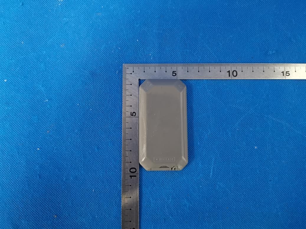
2AVFRPF-240S
Jan 15, 2020BlueDrive S Power Fin
Equipment Class
DTS - Digital Transmission System