2AVFX-GENEVATIMEGENEVA TIME
Huizhou LEMEDIA Technology Co.,Limited
Click to zoom
Application Details
- Equipment Class
- DSS - Part 15 Spread Spectrum Transmitter
- Date of Grant
- Nov 21, 2022
- Application Purpose
- Original Equipment
- Date of Application
- Nov 21, 2022
- Equipment Note
- GENEVA TIME
- Frequency Range
- 2402.00000000 - 2480.00000000
- Country
- China
Documents & Files
Document Text
Text extracted from the exhibit documents filed with the FCC. Open a document above to read the original.
Users Manual
Safety Instructions (FCC) NOTE: This equipment has been tested and found to comply with the limits for a Class B digital device, pursuant to part 15 of the FCC Rules. These limits are designed to provide reasonable protection against harmful interference in a residential installation. This equipment generates uses and can radiate radio frequency energy and, if not installed and used in accordance with the instructions, may cause harmful interference to radio communications. However, there is no guarantee that interference will not occur in a particular installation. If this equipment does cause harmful interference to radio or television reception, which can be determined by turning the equipment off and on, the user is encouraged to try to correct the interference by one or more of the following measures: - Reorient or relocate the receiving antenna. - Increase the separation between the equipment and receiver. -Connect the equipment into an outlet on a circuit different from that to which the receiver is connected. -Consult the dealer or an experienced radio/TV technician for help. -Changes or modifications not expressly approved by the party responsible for compliance could void the user’s authority to operate the equipment. This device contains licence-exempt transmitter(s)/receiver(s) that comply with Innovation, Science and Economic Development Canada’s licence-exempt RSS(s). Operation is subject to the following two conditions: (1) This device may not cause interference. (2) This device must accept any interference, including interference that may cause undesired operation of the device. L’émetteur/récepteur exempt de licence contenu dans le présent appareil est conforme aux CNR d’Innovation, Sciences et Développement économique Canada applicables aux appareils radio exempts de licence. L’exploitation est autorisée aux deux conditions suivantes : (1) L’appareil ne doit pas produire de brouillage; (2) L’appareil doit accepter tout brouillage radioélectrique subi, même si le brouillage est susceptible d’ en compromettre le fonctionnement. Safety Instructions Please store this instruction manual for future reference. • WARNING: To reduce the risk of fire or electric shock, do not expose this apparatus to rain or moisture. The apparatus shall not be exposed to dripping or splashing and that objects filled with liquids, such as vases, shall not be placed on apparatus. • WARNING: The direct plug-in adapter is used as disconnect device, the disconnect device shall remain readily operable. • This lightning flash with arrowhead symbol within an equilateral triangle is intended to alert the user to the presence of non-insulated “dangerous voltage” within the product’s enclosure that may be of sufficient magnitude to constitute a risk of electric shock. • Warning: To reduce the risk of electric shock, do not remove cover (or back) as there are no user- serviceable parts inside. Refer servicing to qualified personnel. • The exclamation point within an equilateral triangle is intended to alert the user to the presence of important operating and maintenance instructions in the literature accompanying the appliance. • Correct Disposal of this product. This marking indicates that this product should not be disposed with other household wastes throughout the EU. To prevent possible harm to the environment or human health from uncontrolled waste disposal, recycle it responsibly to promote the sustainable reuse of material resources. To return your used device, please use the return and collection systems or contact the retailer where the product was purchased. They can take his product for environmental safe recycling. • No naked flame sources, such as lighted candles, should be placed on the apparatus. • Do not use this product near water or moisture. • Clean only with a dry cloth. • Unplug this product from the wall outlet before cleaning. • Place the unit on a solid surface. • Do not put it in a closed bookcase or a cabinet that may keep air from flowing through its ventilation openings. • Do not install near any heat sources, such as radiators, heat registers, stoves or other appliances that produce heat. • Protect the power cord from being walked on or pinched, particularly at plugs and the point where they exit from the product. • Servicing is required when the product has been damaged. Do not attempt to service this product yourself. Opening or removing covers may expose you to dangerous voltages or other hazards. Please contact the manufacturer to be referred to an authorized service center near you. • To prevent risk of fire or electric shock, avoid over loading wall outlets, extension cords, or integral convenience receptacles. • Do not let objects or liquids enter the product. • Use proper power sources. Plug the product into a proper power source, as described in the operating instructions or as marked on the product. • In the rare event you experience an error, unplug the power cord for 60 seconds and then plug it back in firmly. 1. On / Off / Volume dial Rotate the dial clockwise to switch on GENEVA TIME. Rotate clockwise to increase volume Rotate anti-clockwise to decrease volume and to switch OFF 2. Speaker LED in Bluetooth mode (See “Bluetooth”chapter for more informations): - blinking blue: GENEVA TIME is in pairing mode - fix blue: GENEVA TIME is paired to a device in Line-IN / AUX mode - LED is red NOTE: after 5 minutes non-playing, GENEVA TIME turns automatically off. To turn it on please rotate anticlockwise until you hear the click sound, then rotate clockwise again to switch it on 3. Alarm ON LED. Set alarm time by rotating the dial “SET ALARM” on the back of the product. If the LED is RED, Alarm is ON 4. Alarm ON/OFF button If the button is pressed, alarm is ON (LED is ON) 1 234 1. Battery slot for clock. Use AA 1.5V battery only 2. Rotate the “set clock” dial to adjust time. 3. Line In connector 4. USB charge connector. Max output is 5V - 1A 5. Set alarm dial 6. AC-DC adap…
Text truncated - open the document above for the full version.
Cover Letter(s)
Huizhou LEMEDIA Technology Co.,Limited Agent Authorization Company: Huizhou LEMEDIA Technology Co.,Limited Address: Yuanzhou Town, BOLUO County, Huizhou City, Guangdong Province, China Product Name: GENEVA TIME Model Number(s): J002 Product Description: GENEVA TIME We authorize MiCOM Labs Inc., 575 Boulder Court, Pleasanton, California 94566, USA, to act on our behalf on all matters concerning the certification of above named equipment. We declare that MiCOM Labs Inc. is allowed to forward all information related to the approval and certification of equipment to the regulatory agencies as required and to discuss any issues concerning the approval application. Any and all acts carried out by MiCOM Labs on our behalf shall have the same effect as acts of our own. Signature: Date: 2022-11-04 Name: Angel wang Company: HuiZhou LEMEDIA TECHNOLOGY Co., Limited
External Photos
Report No.: AGC14413220601AP02 Page 1 of 5 EXTERNAL PHOTOS ALL VIEW OF EUT TOP VIEW OF EUT Report No.: AGC14413220601AP02 Page 2 of 5 BOTTOM VIEW OF EUT FRONT VIEW OF EUT Report No.: AGC14413220601AP02 Page 3 of 5 BACK VIEW OF EUT LEFT VIEW OF EUT Report No.: AGC14413220601AP02 Page 4 of 5 RIGHT VIEW OF EUT PORT VIEW OF EUT Report No.: AGC14413220601AP02 Page 5 of 5 ADAPTER VIEW OF EUT ****************************************End of Report****************************************
ID Label/Location Info
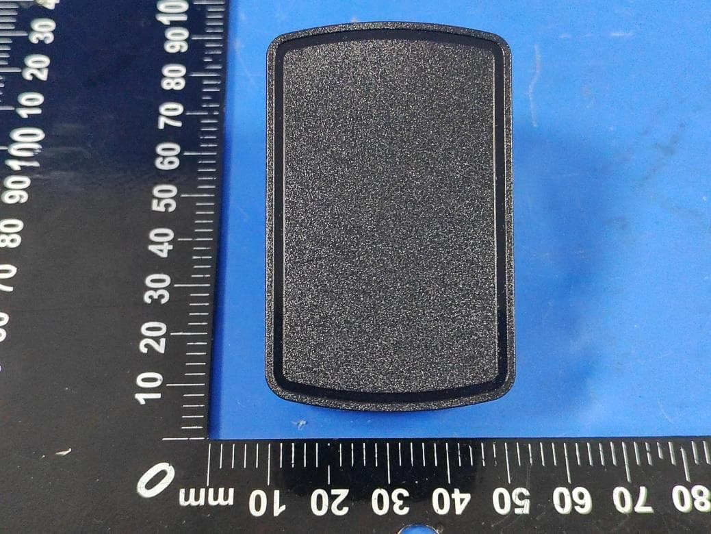
FCC ID Label Location 40mm&40mm FCC ID: 2AVFX-GENEVATIME
Internal Photos
Report No.: AGC14413220601AP02 Page 1 of 6 INTERNAL PHOTOS OPEN VIEW OF EUT INTERNAL VIEW OF EUT (FIGURE 1) Report No.: AGC14413220601AP02 Page 2 of 6 INTERNAL VIEW OF EUT (FIGURE 2) INTERNAL VIEW OF EUT (FIGURE 3) Report No.: AGC14413220601AP02 Page 3 of 6 INTERNAL VIEW OF EUT (FIGURE 4) INTERNAL VIEW OF EUT (FIGURE 5) Report No.: AGC14413220601AP02 Page 4 of 6 INTERNAL VIEW OF EUT (FIGURE 6) INTERNAL VIEW OF EUT (FIGURE 7) Report No.: AGC14413220601AP02 Page 5 of 6 INTERNAL VIEW OF EUT (FIGURE 8) ANTENNA CLOSE-UP PHOTO-1 BT Antenna Report No.: AGC14413220601AP02 Page 6 of 6 ANTENNA CLOSE-UP PHOTO-2 ****************************************End of Report**************************************** WPT Antenna
RF Exposure Info
RF EXPOSURE EVALUATION 1. PRODUCT INFORMATION Product Description GENEVA TIME Model Name J002 FCC ID 2AVFX-GENEVATIME 2. EVALUATION METHOD According to 447498 D01 General RF Exposure Guidance v06 The 1-g and 10-g SAR test exclusion thresholds for 100 MHz to 6 GHz at test separation distances ≤ 50 mm are determined by: [(max. power of channel, including tune-up tolerance, mW)/(min. test separation distance, mm)] ·[√f(GHz)] ≤ 3.0 for 1-g SAR and ≤ 7.5 for 10-g extremity SAR. Where f(GHz) is the RF channel transmit frequency in GHz Power and distance are rounded to the nearest mW and mm before calculation 3. CALCULATION P t =0.175dBm=1.04mW The value of the Maximum output power P t is referred to the test report of the CFR47 §15.247. The result for RF exposure evaluation SAR=(1.04mW /5mm) .[√2.402GHz)]=0.32<3.0 for 1-g SAR and ≤ 7.5 for 10-g extremity SAR. 4. CONCLUSION The SAR evaluation is not required.
Test Report
Inverted F Antenna Specification Summary ITEMANT SPEC Model Name 2.4G ANT HorizontalVertical 2400MHz 2400MHz2500MHz2400MHz2400MHz 2500MHz Center Frequency -1.26-0.76 0.0-5.25-2.46-1.86 MAX. Gain 0.0dBi PolarizationHorizontal and Vertical Azimuth Beam Pattern Omni-directional Impedance50 Ohm Antenna Length 38.20mm Manufacture ZHUHAI JIELI TECHNOLOGY CO.,LTD Antenna Photo & Length (mm) Horizontal: 2400 MHz 2450 MHz 2500 MHz Power (dBm) Max: 0 Min: -40 Scale: 5/div Gain(dBi) Frequency (MHz) MaxMinAvg 2400-1.26174-30.0801-7.18716 2450-0.765802-36.5604-7.48023 2500 0.00000 -22.0315-6.59127 Vertical: 2400 MHz 2450 MHz 2500 MHz Power (dBm) Max: 0 Min: -30 Scale: 5/div Gain(dBi) Frequency (MHz) MaxMinAvg 2400-5.2537-22.1424-12.4294 2450-2.4652-24.5837-10.4702 2500-1.86120-29.5214-9.20432
Test Report
Page 1 of 69 FCC Test Report Report No.: AGC14413220601FE03 FCC ID : 2AVFX-GENEVATIME APPLICATION PURPOSE : Original Equipment PRODUCT DESIGNATION : GENEVA TIME BRAND NAME : N/A MODEL NAME : J002 APPLICANT : HuiZhou LEMEDIA TECHNOLOGY Co., Limited DATE OF ISSUE : Sep. 10, 2022 STANDARD(S) : FCC Part 15.247 REPORT VERSION : V1.0 Attestation of Global Compliance (Shenzhen) Co., Ltd Report No.: AGC14413220601FE03 Page 2 of 69 REPORT REVISE RECORD Report Version Revise Time Issued Date Valid Version Notes V1.0 / Sep. 10, 2022 Valid Initial Release Report No.: AGC14413220601FE03 Page 3 of 69 TABLE OF CONTENTS 1. VERIFICATION OF CONFORMITY .................................................................................................................. 5 2. GENERAL INFORMATION .............................................................................................................................. 6 2.1. PRODUCT DESCRIPTION ........................................................................................................................ 6 2.2. TABLE OF CARRIER FREQUENCYS ....................................................................................................... 6 2.3. RECEIVER INPUT BANDWIDTH .............................................................................................................. 7 2.4. EXAMPLE OF A HOPPING SEQUENCY IN DATA MODE ......................................................................... 7 2.5. EQUALLY AVERAGE USE OF FREQUENCIES AND BEHAVIOUR ......................................................... 7 2.6. RELATED SUBMITTAL(S) / GRANT (S) .................................................................................................... 8 2.7. TEST METHODOLOGY ............................................................................................................................. 8 2.8. SPECIAL ACCESSORIES ......................................................................................................................... 8 2.9. EQUIPMENT MODIFICATIONS ................................................................................................................. 8 2.10. ANTENNA REQUIREMENT..................................................................................................................... 8 3. MEASUREMENT UNCERTAINTY ................................................................................................................... 9 4. DESCRIPTION OF TEST MODES ................................................................................................................. 10 5. SYSTEM TEST CONFIGURATION ................................................................................................................. 11 5.1. CONFIGURATION OF EUT SYSTEM ....................................................................................................... 11 5.2. EQUIPMENT USED IN TESTED SYSTEM ............................................................................................... 11 5.3. SUMMARY OF TEST RESULTS ............................................................................................................... 11 6. TEST FACILITY .............................................................................................................................................. 12 7. PEAK OUTPUT POWER ................................................................................................................................ 13 7.1. MEASUREMENT PROCEDURE ............................................................................................................. 13 7.2. TEST SET-UP (BLOCK DIAGRAM OF CONFIGURATION) .................................................................... 13 7.3. LIMITS AND MEASUREMENT RESULT .................................................................................................. 14 8. 20DB BANDWIDTH ........................................................................................................................................ 19 8.1. MEASUREMENT PROCEDURE ............................................................................................................. 19 8.2. TEST SET-UP (BLOCK DIAGRAM OF CONFIGURATION) .................................................................... 19 8.3. LIMITS AND MEASUREMENT RESULTS ............................................................................................... 20 9. CONDUCTED SPURIOUS EMISSION........................................................................................................... 25 9.1. MEASUREMENT PROCEDURE ............................................................................................................. 25 9.2. TEST SET-UP (BLOCK DIAGRAM OF CONFIGURATION) .................................................................... 25 9.3. MEASUREMENT EQUIPMENT USED .................................................................................................... 25 9.4. LIMITS AND MEASUREMENT RESULT .................................................................................................. 25 10. RADIATED EMISSION ................................................................................................................................. 46 Report No.: AGC14413220601FE03 Page 4 of 69 10.1. MEASUREMENT PROCEDURE ........................................................................................................... 46 10.2. TEST SETUP ......................................................................................................................................... 48 10.3. LIMITS AND MEASUREMENT RESULT ............................................................................................... 49 10.4. TEST RESULT........................................................................................................................................ 49 11. NUMBER OF HOPPING FREQUENCY ....................................................................…
Text truncated - open the document above for the full version.
Test Report
Report No.: AGC14413220601FE03 Page 59 of 69 11. NUMBER OF HOPPING FREQUENCY 11.1. MEASUREMENT PROCEDURE The EUT shall have its hopping function enabled. Use the following spectrum analyzer settings: 1. Span: The frequency band of operation. Depending on the number of channels the device supports, it may be necessary to divide the frequency range of operation across multiple spans, to allow the individual channels to be clearly seen. 2. RBW: To identify clearly the individual channels, set the RBW to less than 30% of the channel spacing or the 20 dB bandwidth, whichever is smaller. 3. VBW ≥ RBW. Sweep: Auto. Detector function: Peak. Trace: Max hold. 4. Allow the trace to stabilize. 11.2. TEST SETUP (BLOCK DIAGRAM OF CONFIGURATION) Same as described in section 8.2 11.3. MEASUREMENT EQUIPMENT USED The same as described in section 6 11.4. LIMITS AND MEASUREMENT RESULT Test Data of Number of Hopping Frequency Test Mode Number of Hopping Frequency Limits Pass or Fail GFSK Hopping 79 >=15 Pass Test Graphs of Number of Hopping Frequency Test_Graph_BR_HOP_ANT1_NA_1Mbps_Number of Hopping Note: The GFSK modulation is the worst case and recorded in the report. Report No.: AGC14413220601FE03 Page 60 of 69 12. TIME OF OCCUPANCY (DWELL TIME) 12.1. MEASUREMENT PROCEDURE The EUT shall have its hopping function enabled. Use the following spectrum analyzer settings: 1. Span: Zero span, centered on a hopping channel. 2. RBW shall be≤channel spacing and where possible RBW should be set >> 1 / T, where T is the expected dwell time per channel. 3. Sweep: As necessary to capture the entire dwell time per hopping channel; where possible use a video trigger and trigger delay so that the transmitted signal starts a little to the right of the start of the plot. The trigger level might need slight adjustment to prevent triggering when the system hops on an adjacent channel; a second plot might be needed with a longer sweep time to show two successive hops on a channel. 4. Detector function: Peak. Trace: Max hold. 5. Use the marker-delta function to determine the transmit time per hop. 6. Repeat the measurement using a longer sweep time to determine the number of hops over the period specified in the requirements. The sweep time shall be equal to, or less than, the period specified in the requirements. Determine the number of hops over the sweep time and calculate the total number of hops in the period specified in the requirements, using the following equation: (Number of hops in the period specified in the requirements) = (number of hops on spectrum analyzer) × (period specified in the requirements / analyzer sweep time). 7. The average time of occupancy is calculated from the transmit time per hop multiplied by the number of hops in the period specified in the requirements. 12.2. TEST SETUP (BLOCK DIAGRAM OF CONFIGURATION) Same as described in section 8.2 12.3. MEASUREMENT EQUIPMENT USED The same as described in section 6 12.4. LIMITS AND MEASUREMENT RESULT Test Data of Dwell Time Channel Time of Pulse for DH5 (ms) Number of hops in the period specified in the requirements Sweep Time (ms) Limit (ms) Pass or Fail 2402 2.887 20.0*4 230.960 400 Pass 2441 2.887 26.0*4 300.248 400 Pass 2480 2.887 22.0*4 254.056 400 Pass Note: The GFSK modulation is the worst case and recorded in the report. Report No.: AGC14413220601FE03 Page 61 of 69 Test Graphs of Dwell Time Test_Graph_BR_HOP_ANT1_NA_1Mbps_2402_Number of Busrt Test_Graph_BR_HOP_ANT1_NA_1Mbps_2402_Time per Burst Report No.: AGC14413220601FE03 Page 62 of 69 Test_Graph_BR_HOP_ANT1_NA_1Mbps_2441_Number of Busrt Test_Graph_BR_HOP_ANT1_NA_1Mbps_2441_Time per Burst Report No.: AGC14413220601FE03 Page 63 of 69 Test_Graph_BR_HOP_ANT1_NA_1Mbps_2480_Number of Busrt Test_Graph_BR_HOP_ANT1_NA_1Mbps_2480_Time per Burst Report No.: AGC14413220601FE03 Page 64 of 69 13. FREQUENCY SEPARATION 13.1. MEASUREMENT PROCEDURE The EUT shall have its hopping function enabled. Use the following spectrum analyzer settings: 1. Span: Wide enough to capture the peaks of two adjacent channels. 2. RBW: Start with the RBW set to approximately 30% of the channel spacing; adjust as necessary to best identify the center of each individual channel. 3. Video (or average) bandwidth (VBW) ≥ RBW. 4. Sweep: Auto. e) Detector function: Peak. f) Trace: Max hold. g) Allow the trace to stabilize. Use the marker-delta function to determine the separation between the peaks of the adjacent channels. 13.2. TEST SETUP (BLOCK DIAGRAM OF CONFIGURATION) Same as described in section 6.2 13.3. MEASUREMENT EQUIPMENT USED The same as described in section 6.3 13.4. LIMITS AND MEASUREMENT RESULT Test Data of Frequency Separation Test Mode Channel Separation (MHz) Limits Pass or Fail GFSK Hopping 1.005 >= 2/3 -20dB BW Pass Test Graphs of Number of Hopping Frequency Test_Graph_BR_HOP_ANT1_NA_1Mbps_Hopping Separation Note: The GFSK modulation is the worst case and recorded in the report. Report No.: AGC14413220601FE03 Page 65 of 69 14. LINE CONDUCTED EMISSION TEST 14.1. LIMITS OF LINE CONDUCTED EMISSION TEST Frequency Maximum RF Line Voltage Q.P. (dBμV) Average (dBμV) 150kHz~500kHz 66-56 56-46 500kHz~5MHz 56 46 5MHz~30MHz 60 50 Note: 1. The lower limit shall apply at the transition frequency. 2. The limit decreases linearly with the logarithm of the frequency in the range 0.15 MHz to 0.50 MHz. 14.2. BLOCK DIAGRAM OF LINE CONDUCTED EMISSION TEST EUT & Support Units Report No.: AGC14413220601FE03 Page 66 of 69 14.3. PRELIMINARY PROCEDURE OF LINE CONDUCTED EMISSION TEST 1. The equipment was set up as per the test configuration to simulate typical actual usage per the user’s manual. When the EUT is a tabletop system, a wooden table with a height of 0.8 meters is used and is placed on the ground plane as per ANSI C63.10 (see Test Facility for the dimensions of the ground plane used). When the EUT is a floor-standing equipment, it is placed on the ground plane which has a 3-12 mm non-conductive covering to insulate the EUT from the gro…
Text truncated - open the document above for the full version.
Test Setup Photos
Report No.: AGC14413220601AP01 Page 1 of 5 TEST SETUP PHOTOS RADIATED EMISSION TEST SETUP 9KHz-30MHz RADIATED EMISSION TEST SETUP 30MHz-1GHz Report No.: AGC14413220601AP01 Page 2 of 5 RADIATED EMISSION TEST SETUP ABOVE 1GHz AC POWER LINE CONDUCTED TEST SETUP Report No.: AGC14413220601AP01 Page 3 of 5 RF CONDUCTED TEST SETUP RF HEALTH ASSESSMENT TEST PHOTOS Position E Report No.: AGC14413220601AP01 Page 4 of 5 Position A Position B Report No.: AGC14413220601AP01 Page 5 of 5 Position C Position D ****************************************End of Report*************************************
Contact Information
Applicant
Angel wang
Technical Contact
Test Firm
Attestation of Global Compliance (Shenzhen) Co., LDoris Li
[email protected]+86-755-25234088
Technical Specifications
| # | Rule Parts | Frequency Range | Power Output |
|---|---|---|---|
| 1 | 15C | 2.40 GHz - 2.48 GHz | 1.00 mW |
Other Applications from Huizhou LEMEDIA Technology Co.,Limited
2AVFX-FK-IR1S
Jul 03, 2026Radio
Equipment Class
DSS - Part 15 Spread Spectrum Transmitter
2AVFX-NR400
Jul 24, 2023Internet Radio
Equipment Class
DTS - Digital Transmission System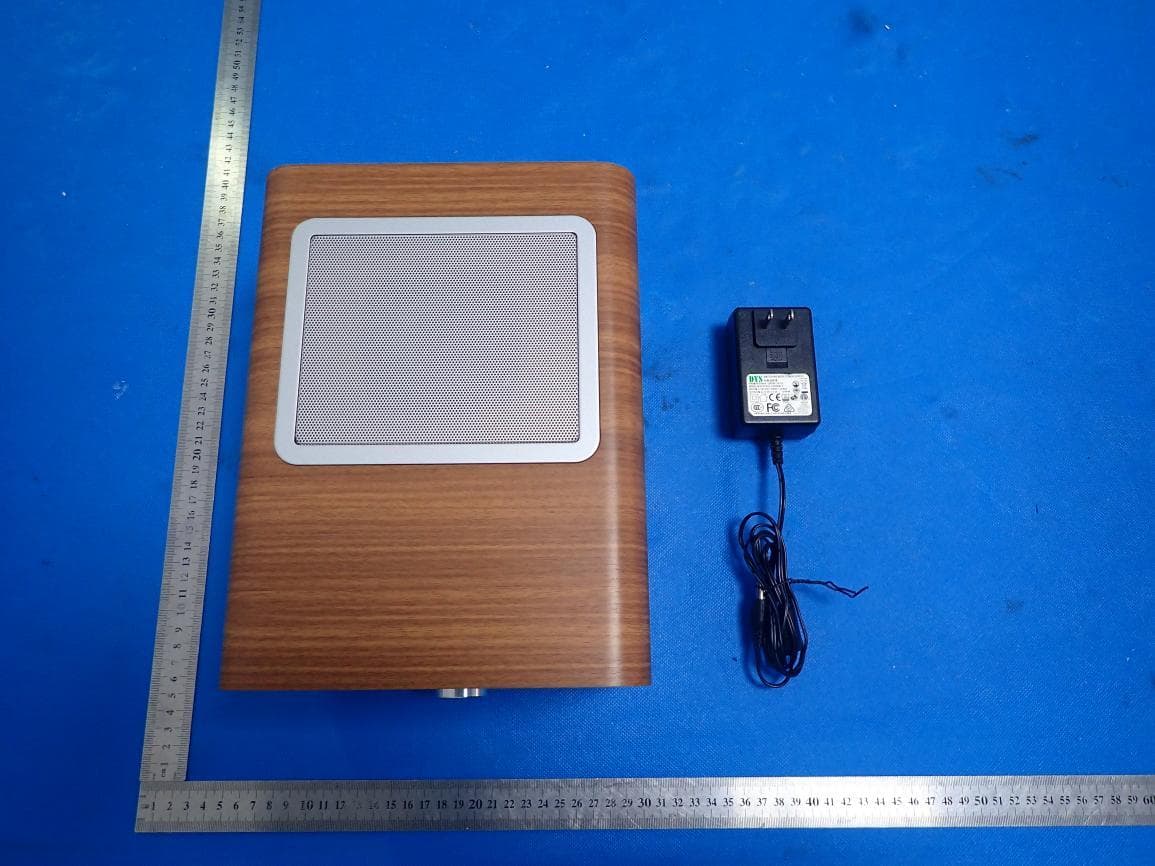
2AVFX-MSY2
Apr 18, 2021MSY2 ALL-IN-ONE-MUSIC SYSTEM
Equipment Class
DSS - Part 15 Spread Spectrum Transmitter