2AVMLSMFIL1Sensor
SmartAC.com, Inc.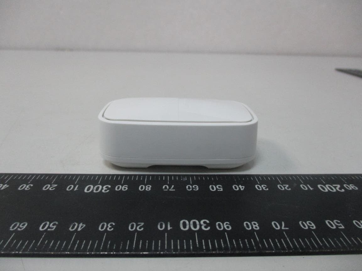
Click to zoom
Application Details
- Equipment Class
- DXX - Part 15 Low Power Communication Device Transmitter
- Date of Grant
- Sep 24, 2020
- Application Purpose
- Original Equipment
- Date of Application
- Sep 21, 2020
- Equipment Note
- Sensor
- Frequency Range
- 2407.00000000 - 2477.00000000
- Company
- SmartAC.com, Inc.
- Country
- United States
Documents & Files
Document Text
Text extracted from the exhibit documents filed with the FCC. Open a document above to read the original.
Users Manual
HARDWARE KIT Product Information 1Version 01. SMACGI-D05-A1 This Product Information guide contains safety, handling, disposal and recycling, regulatory, and software license information, as well warranty information for the SmartAC.com Hardware Kit. Read all safety information and operating instructions below before using the SmartAC.com Hardware Kit to avoid injury. For detailed operating instructions, including any updates to the safety and regulatory information, visit help.smartAC.com SmartAC.com Hardware Kit To use the SmartAC.com Hardware Kit, you need: • A central air/ducted HVAC system, and • Access to an 802.11 wireless network on a 2.4GHz frequency band or an Ethernet network and Internet, and • A smartphone with access to the Apple App Store or Google Play SmartAC.com Hub top view: SmartAC.com Hub rear view: 2SmartAC.com Hardware Kit - Product Information SmartAC.com Sensor front view: SmartAC.com Sensor front view (battery cover removed): SmartAC.com Sensor back view: 3Version 01. SMACGI-D05-A1 Getting started with the SmartAC.com Hardware Kit Before you start, make sure you have physical access to your home router or know your wireless network name (and password if the network is password-protected). If you’re using a wired network, use the provided Ethernet cable to connect your SmartAC.com Hub. 1. Download the SmartAC.com app from the Apple App Store or Google Play (using your camera, you can scan the code above to download the app) 2. Confirm or register your SmartAC.com account 3. Follow video-guided install instructions How to replace the batteries in your SmartAC.com sensors Follow these steps to remove and replace the batteries in your SmartAC.com sensor devices (Comfort, Filter, or Water). Note: Replace only with a SmartAC.com approved batteries. For a list of suitable replacements, visit help.smartAC.com 1. Identify the textured area of the Battery Cover on the front of the sensor device (this is the lower half, below the SmartAC.com logo and eject symbol at the bottom). 4SmartAC.com Hardware Kit - Product Information 2. Placing your thumb on the textured area, gently push and slide the cover. 3. Remove the old batteries. Important: Dispose of batteries according to your local environmental laws and guidelines. 4. With the negative (-) end of the battery oriented toward the top of the device, insert each new battery, pushing up to compress the spring and pushing down to seat the positive end (+). The indicator light will light up immediately when both batteries are installed and the device powers on. 5. Replace the Battery Cover by sitting it in position and sliding down from the top. 5Version 01. SMACGI-D05-A1 Mounting Clip The magnetic mounting clip allows the Comfort sensor to be installed on vents made from non-magnetic materials or with unusual geometry. SmartAC.com Magnetic Mounting Clip side view: SmartAC.com Magnetic Mounting Clip front view: SmartAC.com Magnetic Mounting Clip back view: 6SmartAC.com Hardware Kit - Product Information The Magnetic Mounting Clip articulates through two axes. 1. The rubber grip rotates independently through 360 degrees in a CLOCKWISE/RIGHT- HAND direction. 2. The arm pivots through 90 degrees in relation to the body. 7Version 01. SMACGI-D05-A1 About the SmartAC.com Hub status light The status light on the top of the Hub indicates the following: If the Hub isThe status light... Connected to WiFi with internet accessIs solid blue Off or in standbyIs off Starting upIs solid orange (or red) Is in initial setup modeFlashes orange (or red) slowly In WPS modeFlashes orange (or red) quickly Connected to Wifi with no internet accessIs solid orange (or red) Is in sensor pairing modeFlashes blue About the SmartAC.com Sensor device status light The status light on the front of the sensor devices indicates the following: If the Sensor deviceThe status light... Starting upIs solid for 2 seconds followed by: Flash once = Comfort sensor Flash twice = Filter sensor Flash three times = Water sensor Is off or in standbyIs off Is in sensor pairing modeFlashes blue quickly Has low battery levelFlashes blue periodically Note: Features may be updated or added periodically to SmartAC.com devices via remote firmware upgrades. These changes or upgrades may affect the status light functions listed above. The latest hardware interface specifications, including status light information, are available at help.smartAC.com. 8SmartAC.com Hardware Kit - Product Information Important Safety Instructions WARNING: Failure to follow these safety instructions could result in fire, electric shock, or other injury or damage to SmartAC.com devices or other property. • Read and follow these instructions to use SmartAC.com devices safely. • Keep these instructions. • Heed all warnings. • Follow all instructions. • Do not use the SmartAC.com Hub, Comfort Sensor, or Filter Sensor near water. • Clean only with a dry cloth. • Do not install on or in direct contact with major heat sources such as heating elements, boilers, or other devices that produce extreme heat. • Do not place naked flame sources, such as burners or pilot flames, on or near SmartAC.com devices. • Protect all cords, including the power cord and ethernet cable, from being walked on or pinched, particularly at the plugs and connectors. • Only use attachments/accessories and batteries specified by SmartAC.com. Visit help.smartAC.com for a list of suitable replacements. • Remove the batteries from the sensor devices when depleted or unused for long periods of time. WARNING: To reduce the risk of fire or electric shock, do not expose SmartAC. com devices or accessories to chemicals, excessive heat, or naked flames. Power SmartAC.com Hub and sensor devices have no on/off switch. To disconnect the Hub from power, you must disconnect the power adapter from the device or outlet. To disconnect the sensor devices from power, you must remove the batteries from the device. Power the Hub with the included SmartAC.com …
Text truncated - open the document above for the full version.
Cover Letter(s)
To: Telefication B.V., Dept. FCC TCB Edisonstraat 12A 6902 PK ZEVENAAR The Netherlands Telefication B.V., Dept. FCC TCB.
External Photos
External photo of EUT External photo of EUT External photo of EUT
ID Label/Location Info
FILTER FCC ID LOCATION
Internal Photos
Internal photo of EUT Internal photo of EUT IC Antenna
Test Report
SmartAC.com, Inc. TEST REPORT REPORT NUMBER 200700311TWN-001 ISSUE DATE Sep. 22, 2020 PAGES 22 © 2020 INTERTEK Intertek Report No.: 200700311TWN-001 Page: 1 of 22 This report is for the exclusive use of Intertek's Client and is provided pursuant to the agreement between Intertek and its Client. Intertek's responsibility and liability are limited to the terms and conditions of the agreement. Intertek assumes no liability to any party, other than to the Client in accordance with the agreement, for any loss, expense or damage occasioned by the use of this report. Only the Client is authorized to permit copying or distribution of this report and then only in its entirety. Any use of the Intertek name or one of its marks for the sale or advertisement of the tested material, product or service must first be approved in writing by Intertek. The observations and test results in this report are relevant only to the sample tested. This report by itself does not imply that the material, product, or service is or has ever been under an Intertek certification program. Test Report 0597 Radio Spectrum TEST REPORT Applicant: SmartAC.com, Inc. 5302 Egbert Street, Houston, TX 77007,United States Product: Sensor Model No.: SMFIL1A1 Brand Name: smartAC.com FCC ID: 2AVMLSMFIL1 Test Method/ Standard: 47 CFR FCC Part 15.249 & ANSI C63.10 2013 Test By: Intertek Testing Services Taiwan Ltd., Hsinchu Laboratory No. 11, Lane 275, Ko-Nan 1 Street, Chia-Tung Li, Shiang-Shan District, Hsinchu City, Taiwan Prepared and Checked by: Approved by: Durant Wei Engineer Rico Deng Supervisor Intertek Report No.: 200700311TWN-001 Page: 2 of 22 TEST REPORT Revision History Report No. Issue Date Revision Summary 200700311TWN-001 Sep. 22, 2020 The differences are enclosure color, model number, and loading of electronic sensor component(s) not associated with RF functions. After engineer judgment, the difference does not affect the RF characteristic, no additional tests were considered necessary and then this report based on report of 200700309TWN-001. Intertek Report No.: 200700311TWN-001 Page: 3 of 22 TEST REPORT Table of Contents 1. General Information ............................................................................................................... 5 1.1 Identification of the EUT .................................................................................................. 5 1.2 Antenna description ......................................................................................................... 5 1.3 Peripherals equipment ..................................................................................................... 5 2. Test specifications ................................................................................................................... 6 2.1 Test standard .................................................................................................................... 6 2.2 Operation mode ............................................................................................................... 6 3. 20dB Bandwidth & Occupied Bandwidth test ........................................................................ 7 3.1 Operating environment .................................................................................................... 7 3.2 Test setup & procedure .................................................................................................... 7 3.3 Measured data of modulated bandwidth test results ...................................................... 7 4. Radiated emission test FCC 15.249 (C) ................................................................................... 9 4.1 Operating environment .................................................................................................... 9 4.2 Test setup & procedure .................................................................................................... 9 4.3 Emission limit ................................................................................................................. 11 4.3.1 Fundamental and harmonics emission limits.............................................................. 11 4.3.2 General radiated emission limits ................................................................................. 12 4.4 Radiated spurious emission test data ............................................................................ 12 4.4.1 Measurement results: frequency range from 9 kHz to 30 MHz .................................. 12 4.4.2 Measurement results: frequencies equal to or less than 1 GHz ................................. 13 4.4.3 Measurement results: frequency above 1GHz ............................................................ 15 4.4.4 Measurement results: Fundamental ........................................................................... 16 5. Radiated emission on the band edge FCC 15.249(d) ........................................................... 17 5.1 Operating environment .................................................................................................. 17 5.2 Radiated emission on the band edge test data .............................................................. 17 6. AC Power Line Conducted Emission ..................................................................................... 19 Appendix A: Test equipment list ............................................................................................... 20 Appendix B: Measurement Uncertainty ................................................................................... 22 Intertek Report No.: 200700311TWN-001 Page: 4 of 22 TEST REPORT Summary of Tests Test Reference Results 20dB Bandwidth/Occupied Bandwidth test 15.215(c) Pass Radiated Emission test 15.249(c), 15.209 Pass Emission on the Band Edge 15.249(d) Pass Conducted Emission of AC Power 15.207 N/A Antenna Requirement 15.203 Pass Note: Please note that the test results with statement of conformity, t…
Text truncated - open the document above for the full version.
Test Setup Photos
Radiated Emission Test set-up photo 9kHz~30MHz Radiated Emission Test set-up photo 30MHz~1GHz Radiated Emission Test set-up photo Above 1GHz
Contact Information
Applicant
Joseph Pinzarrone(Head of Manufacturing Operations)
Technical Contact
Intertek Testing Services Taiwan Ltd.Rico Deng
[email protected]886-3-5191411
No. 11, Lane 275, Ko-Nan 1 Street, Chia-Tung Li, · Taiwan
Non-Technical Contact
Intertek Testing Services Taiwan Ltd.Sunny Liu
[email protected]886-3-5191411
Test Firm
Intertek Testing Services Taiwan Ltd.Lily Shih
Technical Specifications
| # | Rule Parts | Frequency Range | Power Output |
|---|---|---|---|
| 1 | 15C | 2.41 GHz - 2.48 GHz | - |
Other Applications from SmartAC.com, Inc.
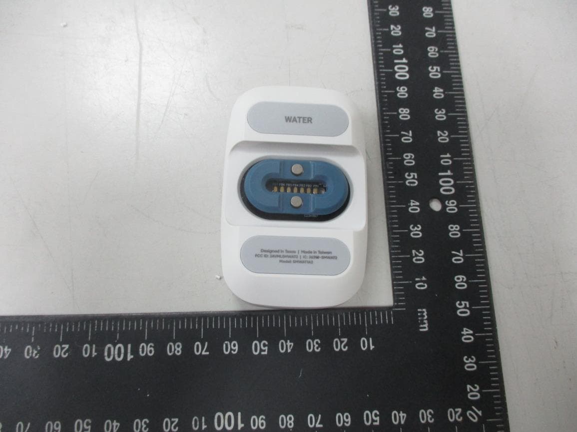
2AVMLSMWAT2
Sep 27, 2022Sensor
Equipment Class
DXX - Part 15 Low Power Communication Device Transmitter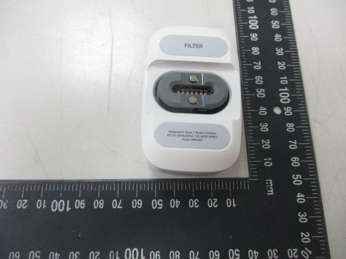
2AVMLSMFIL2
Sep 27, 2022Sensor
Equipment Class
DXX - Part 15 Low Power Communication Device Transmitter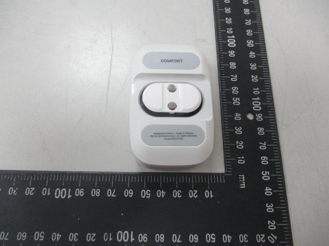
2AVMLSMCOM2
Sep 27, 2022Sensor
Equipment Class
DXX - Part 15 Low Power Communication Device Transmitter2AVMLSMSHB2
May 11, 2022Gateway
Equipment Class
DXX - Part 15 Low Power Communication Device Transmitter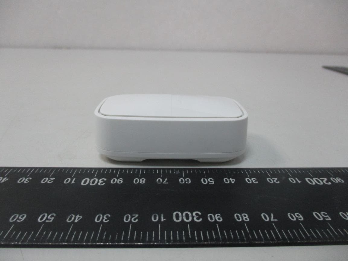
2AVMLSMWAT1
Sep 24, 2020Sensor
Equipment Class
DXX - Part 15 Low Power Communication Device Transmitter