2AVRVCC2400AIO computer
DP AUDIO VIDEO LLC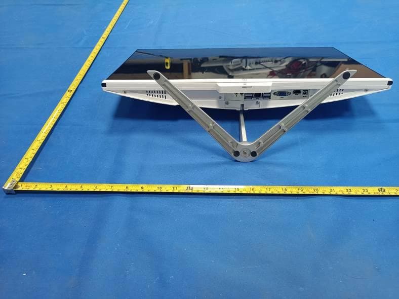
Click to zoom
Application Details
- Equipment Class
- DTS - Digital Transmission System
- Date of Grant
- Jan 16, 2024
- Application Purpose
- Original Equipment
- Date of Application
- Jan 16, 2024
- Equipment Note
- AIO computer
- Frequency Range
- 2412.00000000 - 2462.00000000
- Company
- DP AUDIO VIDEO LLC
- Country
- United States
Documents & Files
Document Text
Text extracted from the exhibit documents filed with the FCC. Open a document above to read the original.
Users Manual
CORE INNOVATIONS TM 24” All-In-One Computer with Windows™ 11 CC2400 User Manual 3 Table of Contents 4 5 7 9 10 11 Read Before Use Device Overview Getting Started Charging and Power Management Connecting to a Wi-Fi ® Network Connecting to a Bluetooth ® Device 14 14 15 15 16 17 18 18 19 19 20 21 22 23 24 User Accounts Sleep, Shut Down, and Restarting Your Device Search Task View Multiple Desktops Snap Windows Action Center The New Microsoft Edge™ Browser Downloading Applications Settings Factory Reset Need Help? Warranty Information 4 feet (2000 meters). 2. Protect your device from impact from bumps and falls. 3. 1. This All-In-One Computer works best in non-tropical areas below 6560 Do not use this device for extended periods of time in environments that are either too cold, too hot, too humid or too dusty. Do not expose the device to direct sunlight. 4. Avoid using this device in strong magnetic and static environments as much as possible. 5. If the device comes into contact with water or any other liquid, power again. 6. Do not clean the device with any cleaning products containing chemicals, to avoid damage caused by corrosion and dampness. When cleaning is necessary, use a dry, soft cloth. 7. The company shall not be held responsible for the loss or deletion of material inside the device caused by abnormal software and hardware operation, maintenance or any other accidents. 8. 9. Please do not disassemble the device by yourself; doing so will void the warranty. Read Before Use 5 Device Overview 78910111012 6 5 4 4 1 23 13 6 Device Overview 1. Display Screen 2. Camera 3. Microphone 4. USB 2.0 Inputs: Connect external USB devices. 5. Restart Button: Use to restart your device. 6. Power Button: Turn your device on or off. Use to set your device to Sleep Mode or to wake it from Sleep Mode. 7. Charging Port: 12V/5A charger. 8. HDMI Port: Connect your computer to a second monitor, TV, or HDMI -enabled devices. 9. VGA 10. USB 3.0 Inputs: Connect external USB devices. 11. RJ45 port 12. Headphone Jack: Transmit audio signals to speakers or headphones. 13. Microphone: Transmits audio signals. ® your device is charging. 7 2. Turn your computer on by pressing and holding the power key for two seconds. 3. new computer. Complete the steps on screen to get started. 4. When the above settings are completed, the system will continue to to a power supply is recommended). The following interface appears, indicating the completion of initialization. Getting Started 1. Fully charge your computer for at least six hours before initial use. Use the included wall charger. The battery indicator will confirm that 8 5. Started] guide in the Start menu. It can help you master various features of Windows™ 11 quickly. When your device is running low on power, a low battery warning will pop up. Please charge the computer in time, otherwise, it will automatically go to sleep. Connect to the power adapter, and the charging indicator light will glow, indicating the device is charging. charging or is fully charged. The battery charges faster when the computer is shut down or goes to sleep. Click the battery icon in the taskbar in the bottom right of the desktop to check the battery level. Getting Started Charging and Power Management 9 2. ® network from the list, and click [Connect]. 3. Enter the network security password if required, and click [Next]. 4. 1. Click the [Network] button in the taskbar in the bottom right of the desktop, and click the right arrow in the pop-up menu. Connecting to a Wi-Fi ® Network 10 2. Right-click the Bluetooth ® icon to open the below menu, and click [Add a Bluetooth ® Device]. 1. At the bottom right of the desktop, click the arrow icon , and then the Bluetooth ® iconwill pop up. Connecting to a Bluetooth ® Device 11 4. In the new pop-up window, select [Bluetooth ® ]. Connecting to a Bluetooth ® Device 3. In the pop-up settings page, click [Add device] on the right. 12 Connecting to a Bluetooth ® Device The system will then search for nearby Bluetooth ® devices. Select the Bluetooth ® device you wish to connect to when it appears on the list. If a pairing code is needed, enter it based on the onscreen prompts. When 14 Enter the [Start] menu from your desktop. On the bottom right side of the Sign-in options: Options for your account. Sleep: Set your device to idle. Shut Down: Restart: automatically turn back on. To add or modify accounts on your device, click on the [Start] icon, then click on the account icon found at the bottom left side of the window. Sleep, Shut Down, and Restarting Your Device Use your information to create a user account. You can use this account to create, modify or remove other accounts on this device. Choose whether you want to use a Microsoft™ account or a local account. Microsoft™ Account Use this account to sign into Windows™ and shop for apps in the allowing you to access them from any device. Local Account You can only use a local account on your computer and cannot connect to the cloud. User Accounts 15 If you have a lot of apps and programs open, there is a new Task View button so you can quickly switch between them. Click [Task View] to see all of your running apps and programs; select any item to open it. Task View Search Search across your device, your cloud storage on OneDrive, and across the Web at the same time. Simply open the Start menu and type in the search box - Windows™ search will do the rest. You can also open search directly from the taskbar; click [Search] and start typing. 16 programs, try adding a desktop. It’ll keep things neatly organized for you. Or, create a desktop for the things you do at work and one for the things you do at home. Select [Task View] from the taskbar, and then click [Add a desktop]. A thumbnail will show up at the bottom of the Task View page. Click the blank thumbnail to open up a clean desktop. To switch between desktops, click [Task View] and then choose a desktop from the bottom of the page. Multiple Desktops 17…
Text truncated - open the document above for the full version.
Attestation Statements
0029264256 [email protected]
Cover Letter(s)
Sincerely, Name/Title: Roy Ryan/Manager Company: DP AUDIO VIDEO LLC Address: 1001 Gayley Avenue P.O. Box 24857, Los Angeles California United States Phone: (310) 966-1134 Fax: (310) 966-1134 E-Mail: [email protected]
External Photos
FCC ID: 2AVRVCC2400 External Photos of the EUT Photo 1 Photo 2 Photo 3 FCC ID: 2AVRVCC2400 Photo 4 Photo 5 Photo 6 FCC ID: 2AVRVCC2400 Photo 7
ID Label/Location Info
Label and Location Size: L: 4.0cm*W: 3.0cm Label and Location Model No.: CC2400 FCC ID : 2AVRVCC2400 Caution : This device complies with part 15 of the FCC Rules. Operation is subject to the following two conditions: (1) This device may not cause harmful interference, and (2) this device must accept any interference received, including interference that may cause undesired operation.
Internal Photos
FCC ID: 2AVRVCC2400 Internal Photos of the EUT Photo 1 Photo 2 Photo 3 FCC ID: 2AVRVCC2400 Photo 4 Photo 5 Photo 6 FCC ID: 2AVRVCC2400 Photo 7 Photo 8 Photo 9 BT/2.4G WIFI PIFA Antenna 1 2.4G WIFI PIFA Antenna 2 FCC ID: 2AVRVCC2400 Photo 10 Photo 11 Photo 12 FCC ID: 2AVRVCC2400 Photo 13 Photo 14 Photo 15 FCC ID: 2AVRVCC2400 Photo 16 Photo 17 Photo 18 FCC ID: 2AVRVCC2400 Photo 19 Photo 20 Photo 21 FCC ID: 2AVRVCC2400 Photo 22 Photo 23 Photo 24 FCC ID: 2AVRVCC2400 Photo 25 Photo 26 Photo 27 FCC ID: 2AVRVCC2400 Photo 28 Photo 29 Photo 30
RF Exposure Info
RF Exposure evaluation FCC ID: 2AVRVCC2400 Exposure category: General population/uncontrolled environment EUT Type: Production Unit Device Type: Mobile Device 1. Reference According to §1.1307(b)(1), systems operating under the provisions of this section shall be operated in a manner that ensures that the public is not exposed to radio frequency energy level in excess of the Commission’s guidelines. According to §1.1310 and §2.1091 RF exposure is calculated. KDB447498 D01: Mobile and Portable Devices RF Exposure Procedures and Equipment Authorization Policies 2. Limit Limits for Maximum Permissible Exposure (MPE)/Controlled Exposure Frequency Range(MHz) Electric Field Strength(V/m) Magnetic Field Strength(A/m) Power Density (mW/cm²) Averaging Time (minute) Limits for Occupational/Controlled Exposure 0.3 – 3.0 3.0 – 30 30 – 300 300 – 1500 1500 – 100,000 614 1842/f 61.4 / / 1.63 4.89/f 0.163 / / (100) * (900/f 2 )* 1.0 f/300 5 6 6 6 6 6 Limits for Maximum Permissible Exposure (MPE)/Uncontrolled Exposure Frequency Range(MHz) Electric Field Strength(V/m) Magnetic Field Strength(A/m) Power Density (mW/cm²) Averaging Time (minute) Limits for Occupational/Controlled Exposure 0.3 – 3.0 3.0 – 30 30 – 300 300 – 1500 1500 – 100,000 614 824/f 27.5 / / 1.63 2.19/f 0.073 / / (100) * (180/f 2 )* 0.2 f/1500 1.0 30 30 30 30 30 F=frequency in MHz *=Plane-wave equivalent power density 3. MPE Calculation Method Predication of MPE limit at a given distance Equation from page 18 of OET Bulletin 65, Edition 97-01 S=PG/4πR² Where: S=power density P=power input to antenna G=power gain of the antenna in the direction of interest relative to an isotropic radiator R=distance to the center of radiation of the antenna 4. Antenna Information CC2400 can only use antennas certificated as follows provided by manufacturer; Antenna No. Model No. of antenna: Type of antenna: Gain of the antenna (Max.) Frequency range: BT / FPC Antenna 1.59dBi for 2400-2500MHz; 2.4GWIFI ANT 1 / FPC Antenna 1.59dBi for 2400-2500MHz 2.4GWIFI ANT 2 / FPC Antenna 1.84dBi for 2400-2500MHz 5. Manufacturing Tolerance Mode Max. Peak Conducted Output Power (dBm) Max. tune-up BT 0.49 1.0±1 Antenna0 Antenna1 Antenna0 Antenna1 2.4GWIFI 13.96 14.17 14±1 14±1 6. Standalone MPE Result As declared by the Applicant, the EUT is a wireless device used in a fix application, at least 20 cm from any body part of the user or nearby persons; from the maximum EUT RF output power, the minimum separation distance, r =20cm, as well as the gain of the used antenna is refer to section 4, the RF power density can be obtained. Modulation Type Output power Antenna Gain (dBi) Antenna Gain (linear) MPE (mW/cm 2 ) MPE Limits (mW/cm 2 ) dBm mW BT 2.0 1.5849 1.59 1.4421 0.0005 1.0000 2.4GWIFI ANT1 15.0 31.6228 1.59 1.4421 0.0091 1.0000 2.4GWIFI ANT2 15.0 31.6228 1.84 1.5276 0.0096 1.0000 Remark: 1. Output power (Peak) including turn-up tolerance; 2. MPE evaluate distance is 20cm from user manual provide by manufacturer. 7. simultaneous MPE Result 2.4GWIFI ANT1 MPE (Ratio) 2.4GWIFI ANT2 MPE (Ratio) simultaneous MPE (Ratio) MPE Limits (Ratio) 0.0091 0.0096 0.0187 1.0000 8. Conclusion The measurement results comply with the FCC Limit per 47 CFR 2.1091 for the uncontrolled RF Exposure of mobile device. ----------------THE END OF REPORT---------------
Test Report
1. Antenna Description: Antenna type FPC antenna Model CC2400-1 Frequency range 2400-2500MHz Manufacturer Shenzhen Weihejia Electronics Technology Co.,LTD ANT Peak Gain 1.59 dBi 2. Antenna Photo: Length: 35.17mm Width: 33.96mm 3. Test Equipment & Conditions 3.1 Test instrument VSWR is tested using Agilent E5071B connected to a hand mechanism, and the status is free space. 3.2 Test environment and methods 4.Antenna Radiation Pattern 2400MHz 2450MHz 2500MHz
Test Report
1. Antenna Description: Antenna type FPC antenna Model CC2400-2 Frequency range 2400-2500MHz Manufacturer Shenzhen Weihejia Electronics Technology Co.,LTD ANT Peak Gain 1.84 dBi 2. Antenna Photo: Length: 46.58mm Width: 14.02mm 3. Test Equipment & Conditions 3.1 Test instrument VSWR is tested using Agilent E5071B connected to a hand mechanism, and the status is free space. 3.2 Test environment and methods 4.Antenna Radiation Pattern 2400MHz 2450MHz 2500MHz
Test Report
Shenzhen CTA Testing Technology Co., Ltd. Room 106, Building 1, Yibaolai Industrial Park, Qiaotou Community, Fuhai Street, Bao’an District, Shenzhen, China Shenzhen CTA Testing Technology Co., Ltd. Room 106, Building 1, Yibaolai Industrial Park, Qiaotou Community, Fuhai Street, Bao’an District, Shenzhen, China Tel:+86-755 2322 5875 E-mail:[email protected] Web:http://www.cta-test.cn FCC PART 15 SUBPART C TEST REPORT FCC PART 15.247 Report Reference No. ..................... : FCC ID............................................. : CTA23120700502 2AVRVCC2400 Compiled by ( position+printed name+signature) . : File administrators Zoey Cao Supervised by ( position+printed name+signature) . : Project Engineer Amy Wen Approved by ( position+printed name+signature) . : RF Manager Eric Wang Date of issue .................................... : Jan. 03, 2024 Testing Laboratory Name .............. : Shenzhen CTA Testing Technology Co., Ltd. Address............................................ : Room 106, Building 1, Yibaolai Industrial Park, Qiaotou Community, Fuhai Street, Bao‘an District, Shenzhen, China Applicant’s name ............................ : DP Audio Video LLC Address ............................................ : 1001 Gayley Avenue P.O. Box 24857, Los Angeles, California, United States 90024 Test specification ........................... : Standard ........................................... : FCC Part 15.247 TRF Originator .................................. : Shenzhen CTA Testing Technology Co., Ltd. Shenzhen CTA Testing Technology Co., Ltd. All rights reserved. This publication may be reproduced in whole or in part for non-commercial purposes as long as the Shenzhen CTA Testing Technology Co., Ltd. is acknowledged as copyright owner and source of the material. Shenzhen CTA Testing Technology Co., Ltd. takes no responsibility for and will not assume liability for damages resulting from the reader's interpretation of the reproduced material due to its placement and context. Test item description ..................... : AIO computer Trade Mark ....................................... : CORE INNOVATIONS Manufacturer .................................... : Shenzhen Weihejia Electronics Technology Co.,LTD Model/Type reference ...................... : CC2400 Listed Models .................................. : N/A Modulation Type ............................... : CCK/DSSS/ OFDM Operation Frequency ........................ : From 2412 - 2462MHz Rating ............................................... : DC 12.0V From external circuit Result ............................................... : PASS Report No.: CTA23120700502 Page 2 of 48 Shenzhen CTA Testing Technology Co., Ltd. Room 106, Building 1, Yibaolai Industrial Park, Qiaotou Community, Fuhai Street, Bao’an District, Shenzhen, China Tel:+86-755 2322 5875 E-mail:[email protected] Web:http://www.cta-test.cn T E S T R E P O R T Equipment under Test : AIO computer Model /Type : CC2400 Serial Models : N/A Applicant : DP Audio Video LLC Address : 1001 Gayley Avenue P.O. Box 24857, Los Angeles, California, United States 90024 Manufacturer : Shenzhen Weihejia Electronics Technology Co.,LTD Address : Block 102, Building 9, Xihu lndustrial park, Xikeng community, Yuanshan street, Longgang district, Shenzhen. China Test Result: PASS The test report merely corresponds to the test sample. It is not permitted to copy extracts of these test result without the written permission of the test laboratory. Report No.: CTA23120700502 Page 3 of 48 Shenzhen CTA Testing Technology Co., Ltd. Room 106, Building 1, Yibaolai Industrial Park, Qiaotou Community, Fuhai Street, Bao’an District, Shenzhen, China Tel:+86-755 2322 5875 E-mail:[email protected] Web:http://www.cta-test.cn Contents 1 T E S T S T A N D A R D S ................................................................. 4 2 S U M M A R Y ............................................................................ 5 2.1 General Remarks 5 2.2 Product Description 5 2.3 Equipment Under Test 5 2.4 Short description of the Equipment under Test (EUT) 5 2.5 EUT operation mode 5 2.6 Block Diagram of Test Setup 6 2.7 Related Submittal(s) / Grant (s) 6 2.8 Modifications 6 3 T E S T E N V I R O N M E N T .............................................................. 7 3.1 Address of the test laboratory 7 3.2 Test Facility 7 3.3 Environmental conditions 7 3.4 Test Description 8 3.5 Statement of the measurement uncertainty 8 3.6 Equipments Used during the Test 9 4 T E S T C O N D I T I O N S A N D R E S U L T S ........................................... 11 4.1 AC Power Conducted Emission 11 4.2 Maximum Peak Conducted Output Power 20 4.3 Power Spectral Density 22 4.4 6dB Bandwidth 28 4.5 Out-of-band Emissions 33 4.6 Antenna Requirement 46 5 T E S T S E T U P P H O T O S O F T H E E U T ......................................... 47 6 P H O T O S O F T H E E U T ........................................................... 48 Report No.: CTA23120700502 Page 4 of 48 Shenzhen CTA Testing Technology Co., Ltd. Room 106, Building 1, Yibaolai Industrial Park, Qiaotou Community, Fuhai Street, Bao’an District, Shenzhen, China Tel:+86-755 2322 5875 E-mail:[email protected] Web:http://www.cta-test.cn 1 T E S T S T A N D A R D S The tests were performed according to following standards: FCC Rules Part 15.247: Frequency Hopping, Direct Spread Spectrum and Hybrid Systems that are in operation within the bands of 902-928 MHz, 2400-2483.5 MHz, and 5725-5850 MHz. ANSI C63.10-2013: American National Standard for Testing Unlicensed Wireless Devices KDB558074 D01 v05r02: Guidance for Compliance Measurements on Digital Transmission Systems (DTS) ,Frequency Hopping Spread Spectrum System(HFSS), and Hybrid System Devices Operating Under §15.247 of The FCC rules. Report No.: CTA23120700502 Page 5 of 48 Shenzhen CTA Testing Technology Co., Ltd. Room 106, Building 1, Yibaolai Industrial Park, Qiaotou Community, Fuhai Street, Bao’an District, Shenzhen, China Tel:+86-…
Text truncated - open the document above for the full version.
Test Report
Report No.: CTA23120700502 Page 34 of 48 Shenzhen CTA Testing Technology Co., Ltd. Room 106, Building 1, Yibaolai Industrial Park, Qiaotou Community, Fuhai Street, Bao’an District, Shenzhen, China Tel:+86-755 2322 5875 E-mail:[email protected] Web:http://www.cta-test.cn ANT 1 802.11b Reference Reference CH01 CH06 30MHz-3GHz 30MHz-3GHz 3GHz -25GHz 3GHz -25GHz Report No.: CTA23120700502 Page 35 of 48 Shenzhen CTA Testing Technology Co., Ltd. Room 106, Building 1, Yibaolai Industrial Park, Qiaotou Community, Fuhai Street, Bao’an District, Shenzhen, China Tel:+86-755 2322 5875 E-mail:[email protected] Web:http://www.cta-test.cn 802.11b 802.11g Reference Reference CH011 CH01 30MHz-3GHz 30MHz-3GHz 3GHz -25GHz 3GHz -25GHz Report No.: CTA23120700502 Page 36 of 48 Shenzhen CTA Testing Technology Co., Ltd. Room 106, Building 1, Yibaolai Industrial Park, Qiaotou Community, Fuhai Street, Bao’an District, Shenzhen, China Tel:+86-755 2322 5875 E-mail:[email protected] Web:http://www.cta-test.cn 802.11g Reference Reference CH06 CH11 30MHz-3GHz 30MHz-3GHz 3GHz -25GHz 3GHz -25GHz Report No.: CTA23120700502 Page 37 of 48 Shenzhen CTA Testing Technology Co., Ltd. Room 106, Building 1, Yibaolai Industrial Park, Qiaotou Community, Fuhai Street, Bao’an District, Shenzhen, China Tel:+86-755 2322 5875 E-mail:[email protected] Web:http://www.cta-test.cn 802.11n20 Reference Reference CH01 CH06 30MHz-3GHz 30MHz-3GHz 3GHz -25GHz 3GHz -25GHz Report No.: CTA23120700502 Page 38 of 48 Shenzhen CTA Testing Technology Co., Ltd. Room 106, Building 1, Yibaolai Industrial Park, Qiaotou Community, Fuhai Street, Bao’an District, Shenzhen, China Tel:+86-755 2322 5875 E-mail:[email protected] Web:http://www.cta-test.cn 802.11n20 / Reference CH11 / 30MHz-3GHz / 3GHz -25GHz Report No.: CTA23120700502 Page 39 of 48 Shenzhen CTA Testing Technology Co., Ltd. Room 106, Building 1, Yibaolai Industrial Park, Qiaotou Community, Fuhai Street, Bao’an District, Shenzhen, China Tel:+86-755 2322 5875 E-mail:[email protected] Web:http://www.cta-test.cn ANT 2 802.11b Reference Reference CH01 CH06 30MHz-3GHz 30MHz-3GHz 3GHz -25GHz 3GHz -25GHz Report No.: CTA23120700502 Page 40 of 48 Shenzhen CTA Testing Technology Co., Ltd. Room 106, Building 1, Yibaolai Industrial Park, Qiaotou Community, Fuhai Street, Bao’an District, Shenzhen, China Tel:+86-755 2322 5875 E-mail:[email protected] Web:http://www.cta-test.cn 802.11b 802.11g Reference Reference CH011 CH01 30MHz-3GHz 30MHz-3GHz 3GHz -25GHz 3GHz -25GHz Report No.: CTA23120700502 Page 41 of 48 Shenzhen CTA Testing Technology Co., Ltd. Room 106, Building 1, Yibaolai Industrial Park, Qiaotou Community, Fuhai Street, Bao’an District, Shenzhen, China Tel:+86-755 2322 5875 E-mail:[email protected] Web:http://www.cta-test.cn 802.11g Reference Reference CH06 CH11 30MHz-3GHz 30MHz-3GHz 3GHz -25GHz 3GHz -25GHz
Test Report
Report No.: CTA23120700502 Page 42 of 48 Shenzhen CTA Testing Technology Co., Ltd. Room 106, Building 1, Yibaolai Industrial Park, Qiaotou Community, Fuhai Street, Bao’an District, Shenzhen, China Tel:+86-755 2322 5875 E-mail:[email protected] Web:http://www.cta-test.cn 802.11n20 Reference Reference CH01 CH06 30MHz-3GHz 30MHz-3GHz 3GHz -25GHz 3GHz -25GHz Report No.: CTA23120700502 Page 43 of 48 Shenzhen CTA Testing Technology Co., Ltd. Room 106, Building 1, Yibaolai Industrial Park, Qiaotou Community, Fuhai Street, Bao’an District, Shenzhen, China Tel:+86-755 2322 5875 E-mail:[email protected] Web:http://www.cta-test.cn 802.11n20 / Reference CH11 / 30MHz-3GHz / 3GHz -25GHz Report No.: CTA23120700502 Page 44 of 48 Shenzhen CTA Testing Technology Co., Ltd. Room 106, Building 1, Yibaolai Industrial Park, Qiaotou Community, Fuhai Street, Bao’an District, Shenzhen, China Tel:+86-755 2322 5875 E-mail:[email protected] Web:http://www.cta-test.cn Band-edge Measurements for RF Conducted Emissions: ANT 1 802.11b Left bandedge Right bandedge 802.11g Left bandedge Right bandedge 802.11n(HT20) Left bandedge Right bandedge Report No.: CTA23120700502 Page 45 of 48 Shenzhen CTA Testing Technology Co., Ltd. Room 106, Building 1, Yibaolai Industrial Park, Qiaotou Community, Fuhai Street, Bao’an District, Shenzhen, China Tel:+86-755 2322 5875 E-mail:[email protected] Web:http://www.cta-test.cn ANT 2 802.11b Left bandedge Right bandedge 802.11g Left bandedge Right bandedge 802.11n(HT20) Left bandedge Right bandedge Report No.: CTA23120700502 Page 46 of 48 Shenzhen CTA Testing Technology Co., Ltd. Room 106, Building 1, Yibaolai Industrial Park, Qiaotou Community, Fuhai Street, Bao’an District, Shenzhen, China Tel:+86-755 2322 5875 E-mail:[email protected] Web:http://www.cta-test.cn 4.6 Antenna Requirement Standard Applicable For intentional device, according to FCC 47 CFR Section 15.203: An intentional radiator shall be designed to ensure that no antenna other than that furnished by the responsible party shall be used with the device. The use of a permanently attached antenna or of an antenna that uses a unique coupling to the intentional radiator, the manufacturer may design the unit so that a broken antenna can be replaced by the user, but the use of a standard antenna jack or electrical connector is prohibited FCC CFR Title 47 Part 15 Subpart C Section 15.247(c) (1) (I): (i) Systems operating in the 2400-2483.5 MHz band that is used exclusively for fixed. Point-to-point operations may employ transmitting antennas with directional gain greater than 6dBi provided the maximum conducted output power of the intentional radiator is reduced by 1 dB for every 3 dB that the directional gain of the antenna exceeds 6dBi. Test Result: The maximum gain of antenna 1 is 1.59 dBi and the maximum gain of antenna 2 is 1.84 dBi. Remark:The antenna gain is provided by the customer , if the data provided by the customer is not accurate, Shenzhen CTA Testing Technology Co., Ltd. does not assume any responsibility. Report No.: CTA23120700502 Page 47 of 48 Shenzhen CTA Testing Technology Co., Ltd. Room 106, Building 1, Yibaolai Industrial Park, Qiaotou Community, Fuhai Street, Bao’an District, Shenzhen, China Tel:+86-755 2322 5875 E-mail:[email protected] Web:http://www.cta-test.cn 5 T e s t S e t u p P h o t o s o f t h e E U T Report No.: CTA23120700502 Page 48 of 48 Shenzhen CTA Testing Technology Co., Ltd. Room 106, Building 1, Yibaolai Industrial Park, Qiaotou Community, Fuhai Street, Bao’an District, Shenzhen, China Tel:+86-755 2322 5875 E-mail:[email protected] Web:http://www.cta-test.cn 6 P h o t o s o f t h e E U T Reference to the test report No. CTA23120700501. ********************** End of Report **********************
Test Setup Photos
FCC ID: 2AVRVCC2400 Test Setup Photos of the EUT
Contact Information
Applicant
Roy Ryan
Test Firm
SHENZHEN CTA TESTING TECHNOLOGY CO., LTD.Eric Wang
[email protected]+86 755 2322 5875
Technical Specifications
| # | Rule Parts | Frequency Range | Power Output |
|---|---|---|---|
| 1 | 15C | 2.41 GHz - 2.46 GHz | 47.80 mW |
Other Applications from DP AUDIO VIDEO LLC
2AVRVBS500HT
Sep 10, 2024Hot Tub & Pool Bluetooth Floating Speaker
Equipment Class
DSS - Part 15 Spread Spectrum Transmitter
2AVRV-DG3200
Jul 21, 202432inch Rollable Smart Touchscreen TV
Equipment Class
DTS - Digital Transmission System
2AVRVKRMIC200
Jul 10, 2024Portable Karaoke Machine
Equipment Class
DSS - Part 15 Spread Spectrum Transmitter
2AVRVCTP100LG
Jan 08, 2024Professional Wireless Thermal Printer
Equipment Class
DSS - Part 15 Spread Spectrum Transmitter
2AVRVPKCS120
Sep 23, 2023Inflatable Car Pool Speaker
Equipment Class
DSS - Part 15 Spread Spectrum Transmitter