2AVRY-SWX0003Power Pack Enclosure
BLP Technologies, Inc.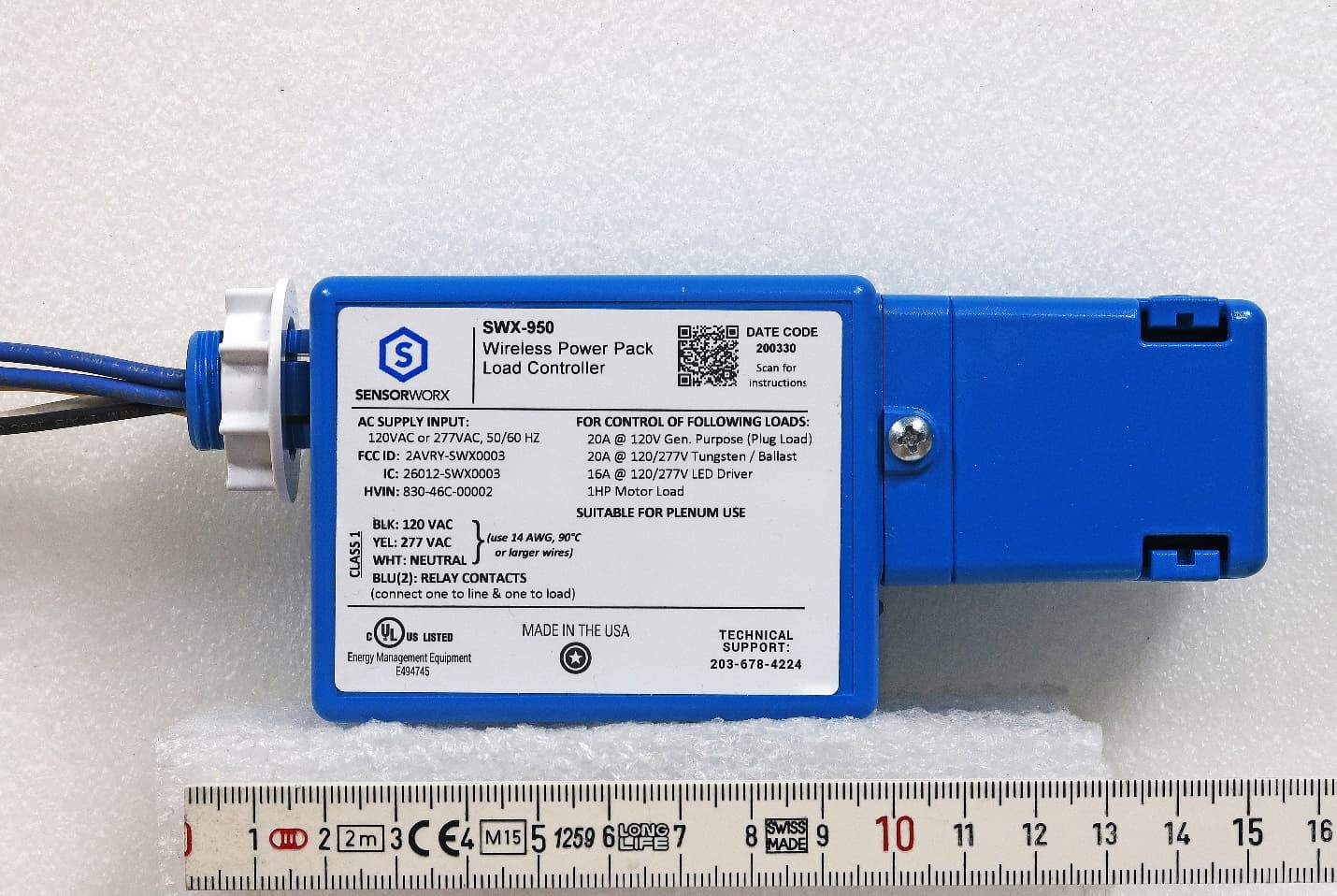
Click to zoom
Application Details
- Equipment Class
- DTS - Digital Transmission System
- Date of Grant
- Jun 11, 2020
- Application Purpose
- Original Equipment
- Date of Application
- Jun 11, 2020
- Equipment Note
- Power Pack Enclosure
- Frequency Range
- 903.00000000 - 927.00000000
- Company
- BLP Technologies, Inc.
- Country
- United States
Documents & Files
Document Text
Text extracted from the exhibit documents filed with the FCC. Open a document above to read the original.
Users Manual
WIRELESS POWER PACK LOAD CONTROLLER INSTALLATION & OPERATION INSTRUCTIONS CATALOG NUMBERSDESCRIPTIONS SWX-950 POWER PACK LOAD CONTROLLER SWX-950-D2 POWER PACK LOAD CONTROLLER W/ 0-10V DIMMING SWX-950-AX POWER PACK LOAD CONTROLLER W/ AUXILIARY LOW VOLTAGE CONTROL SWX-950-AX-D2 POWER PACK LOAD CONTROLLER W/ 0-10V DIMMING & AUXILIARY LOW VOLTAGE CONTROL SWX-999 LOW VOLTAGE WIRING CHAMBER SPECIFICATIONS ELECTRICAL OPERATING VOLTAGE 120/277 VAC, Single Phase, 50/60 Hz CLASS 2 OUTPUT RATINGS 18 VDC, 150 mA (-AX version) RELAY CURRENT REQS 55 mA LOAD RATINGS 20A @ 120 VAC - General Purpose Plug Load 20A @ 120/277 VAC - General Purpose, Tungsten, Magnetic Ballast 16A @ 120/277 VAC - Electronic Ballast, LED Driver DC LOAD RATINGS 20A @ 28 VDC (MAX) 1A @ 5 VDC (MIN) DIMMING LOAD (Models with -D2 option only) 50mA, (0-10 VDC ballasts or drivers compliant with IEC 60929 Annex E.2) MOTOR LOAD 1 HP ESD IMMUNITY Tested to withstand electrostatic discharge without damage or memory loss ENVIRONMENTAL OPERATING TEMP 32°F to 122°F (0°C to 50°C) RELATIVE HUMIDITY 0-95% Non-Condensing Indoor Use Only WIRELESS RANGE 80’ line of site w/o obstruction 40’ with obstruction (walls/floors) FREQUENCY 915 MHz ISM Band WIRELESS LINKING Simple 3 sec. Push Button Process SECURITY All Wireless Data is Encrypted PHYSICAL SIZE 3.00” H x 2.25” W x 1.88” D (7.62 cm x 5.72 cm x 4.78 cm) WEIGHT 6.00 oz. COLOR Blue MOUNTING 1/2” Knockout RELAY TEST BUTTON LED STATUS INDICATOR Bi-color White & Blue OPERATION OPERATING MODES Occupancy & Vacancy Partial On/Off (-D option) TIME DELAY OPTIONS 1, 5, 10, 15, 20, 30 min. CODE COMPLIANCE These power packs can be used to meet ASHRAE 90.1, IECC, & Title 24 energy code requirements FEATURES ÃWirelessly Links to Sensors & Wall Stations ÃPairs in Seconds up to 50 Remote Devices ÃSwitches Up to 20A Line Voltage Loads ÃElectronically Timed Switching Ensures Long Relay Life ÃIntegrated Test/Programming Button ÃConfigurable Time Delays and Operational Modes (e.g. Occupancy/ Vacancy) ÃOptional 0-10V Dimming Output for Partial On & Partial Off Operation ÃOptional Low Voltage Sensor & Wall Station Wired Connectivity ÃPlenum Rated (UL 2043) OVERVIEW SENSORWORX wireless power pack controllers switch on/off power to a connected lighting load as directed by wirelessly linked sensors and wall controls. Additionally, the unit’s 0-10V dimming option enables dimming control. This wireless power pack also has optional auxiliary low voltage connections for achieving hybrid wired/wireless architectures. The SENSORWORX wireless power pack is rated to switch fully loaded circuits and utilizes a powerful microprocessor to optimize its switching timing, ensuring long relay life even when controlling high-inrush LED lighting. As with all SENSORWORX products, these power packs are easy to install and incorporate features which reduce contractor labor time. An elongated chase nipple with snaps for quick installation and an optional snap-on low voltage wire chamber make for a hassle free contractor experience. All SENSORWORX products are proudly made in the USA. BASIC OPERATION A received wireless message indicating occupancy from one or more wirelessly linked sensors will trigger the pack’s integrated relay to close. When configured for Vacancy operation, an ON switch message is required from a wirelessly linked wall station to initially trigger lights. Once closed, line voltage will flow through the relay and turn on the connected lighting load. The wireless power pack maintains a master time delay that is reset every time a linked sensor reports occupancy. Lights will be switched off once there hasn’t been an occupancy message reported for the duration of the time delay. POWER PACKLOW VOLTAGE WIRING CHAMBER [OPTIONAL] PROVIDES 3 KNOCKOUTS FOR CONDUIT CONNECTIONS CHASE NIPPLE HAS SNAPS THAT ENABLE QUICK INSTALLATION THROUGH ANY 1/2 KNOCKOUT TEST/PROGRAMMING BUTTON LED INDICATOR SNAPS DIRECTLY TO MAIN HOUSING WIRING CHAMBER*LOCK NUTSNAP-ON COVER *CONNECT LOW VOLTAGE CHAMBER TO CONDUIT BEFORE CONNECTING TO POWER PACK. CONDUIT SHOULD BE APPROPRIATELY SUPPORTED BY OTHER MEANS AND NOT USE THE LOW VOLTAGE CHAMBER FOR SUPPORT INSTALLATION INSTRUCTIONS MOUNTING INSTRUCTIONS Power Packs are designed to attach to electrical enclosures with 1/2” knockouts. Do not mount unit inside a metal junction box. INSTALLATION NOTES 1 For supply connections, use 14 AWG (90°C) or larger wires. Wire all circuits exiting chase nipple as Class 1 circuits. 2 Suitable for plenum use. 3 Risk of Electric Shock - More than one disconnect switch may be required to de-engergize the equipment before servicing. WARNING: TURN POWER OFF AT THE CIRCUIT BREAKER BEFORE WIRING BLU YEL BLK BLU WHT N 277V 120V OR * CAP UNUSED BLACK OR YELLOW WIRE * * LOAD 120V/ 277V SWX-950 WIRELESS POWER PACK + BLK COMMON 0-10V DIMMING OUTPUT VIO BLU YEL BLK BLU WHT N 277V 120V OR * CAP UNUSED BLACK OR YELLOW WIRE * * DIMMING LOAD 120V/ 277V SWX-950 WIRELESS POWER PACK + - WIRING MODEL #: SWX-950 MODEL #: SWX-950-AX MODEL #: SWX-950-D2 YEL BRN SWITCH OUTPUT RED BLK BRN RED RED BLK BLK WHTWHT CONTROL INPUT ** COMMON +VDC SWITCH INPUT RELAY STATUS SWX LOW VOLTAGE SENSOR SWX-801 SWITCH YEL RELAY STATUS INPUT BLU YEL BLK BLU WHT N 277V 120V 120V/ 277V OR LOAD CLASS 1 WIRING CLASS 2 WIRING * CAP UNUSED BLACK OR YELLOW WIRE * * SWX-950-AX HYBRID WIRELESS POWER PACK ** IF NO SENSORS ARE WIRED OR WIRELESSLY LINKED, CONNECT WHITE WIRE TO RED. RED VIO GRY + 0-10 VDC DIMMING OUTPUT - BRN BLK RED BLK BLU YEL BLK BLU WHT WHT WHT N 277V 120V OR CONTROL INPUT ** COMMON +VDC OUTPUT CLASS 1 WIRING CLASS 2 WIRING * * * CAP UNUSED BLACK OR YELLOW WIRE BRN RED YEL RELAY STATUS SWITCH OUTPUT BLK SWITCH INPUT RELAY STATUS OUTPUT YEL +VDC INPUT COMMON COMMON +VDC INPUT OCCUPANCY OUTPUT ** IF NO SENSORS ARE WIRED OR WIRELESSLY LINKED, CONNECT WHITE WIRE TO RED. LOW VOLTAGE SENSOR (e.g. SWX-201-1) SWX-801 LOW VOLTAGE SWITCH SWX-950-AX-D2 HYBRID WIRELESS/WIRED DIMMING POWER PACK 120V/ 277V 0-10V DI…
Text truncated - open the document above for the full version.
Cover Letter(s)
June 10, 2020 Federal Communications Commission Authorization and Evaluation Division RE: Confidentiality request regarding application for certification of FCC ID: 2AVRY-SWX0003 To Whom It May Concern: Pursuant to 47 CFR Sections 0.457 and 0.459 of the Commission’s Rules, we hereby request confidential treatment of information accompanying this application as outlined below: Type of Confidential Request Exhibit Type File Name Permanent Block Diagram 2AVRY-SWX0003 BlkDia.pdf Permanent Schematic 2AVRY-SWX0003 Schem.pdf Permanent Operational Description 2AVRY-SWX0003 OpDes.pdf Short Term Internal Photos 2AVRY-SWX0003 IntPho.pdf The above materials contain trade secrets and proprietary information not customarily released to the public. The public disclosure of these materials may be harmful to BLP Technologies and provide unjustified benefits to its competitors. BLP Technologies understands that pursuant to Section 0.457 of the Rules, disclosure of this application and all accompanying documentation will not be made before the date of the Grant for this application. Pursuant to DA04-1705 June 15, 2004 of the Commission’s public notice, we also require short term confidential treatment of information for a period of 180 days. This enables BLP Technologies to complete its development and regulatory efforts prior to introducing the product to the marketplace. Releasing information on the product via the FCC website prior to formal market introduction can be confusing to our customers, and places BLP Technologies at a competitive disadvantage. Sincerely, William Fassbender [email protected] BLP Technologies, Inc. Sensorworx 2a Research Parkway Wallingford, CT 06492 203-678-4224 Ext. 110
Cover Letter(s)
April 20, 2020 Federal Communications Commission Authorization and Evaluation Division RE: FCC ID: 2AVRY-SWX0003 To Whom It May Concern: Please be advised that William Fassbender of BLP Technologies, Inc. authorizes Larry Stillings of Compliance Worldwide, Inc. to act on our behalf, until otherwise notified, for applications submitted for the purpose of obtaining an FCC Grant of Equipment Authorization. We certify that we are not subject to denial of federal benefits, that includes FCC benefits, pursuant to Section 5301 of the Anti-Drug Abuse ACT of 1988, U.S.C. 862. Further, no party, as defined in 47 CFR 1.2002(b), to the application is subject to denial of federal benefits, that includes FCC benefits. Thank you for your attention to this matter. Sincerely, William Fassbender [email protected] BLP Technologies, Inc. Sensorworx 2A Research Parkway Wallingford, CT 06492 (203) 678-4224 Ext. 110
External Photos
External Photos – Power Pack – 830-46C-00002 Front Rear Top Bottom Left Right Top Cover Off
ID Label/Location Info
May 1, 2020 Federal Communications Commission Authorization and Evaluation Division RE: FCC ID: 2AVRY-SWX0003, Wireless Power Pack Label Sample Best Regards, William Fassbender BLP Technologies Sensorworx 2a Research Parkway Wallingford, CT 06492 (203) 678-4224 Ext. 110 [email protected]
ID Label/Location Info
May 1, 2020 Federal Communications Commission Authorization and Evaluation Division RE: FCC ID: 2AVRY-SWX0003, Wireless Power Pack Label Location Best Regards, William Fassbender BLP Technologies Sensorworx 2a Research Parkway Wallingford, CT 06492 (203) 678-4224 Ext. 110 [email protected]
Internal Photos
Internal Photos – Power Pack – 830-46C-00002 Front Cover Off Mainboard Front Mainboard Rear Mainboard Front Mainboard Rear Transmitter Module Transmitter Module Front Transmitter Module Front Labeled Transmitter Module Rear
RF Exposure Info
Test Number: 186-20 Issue Date: 4/24/2020 Page 28 of 44 Compliance Worldwide, Inc. - 357 Main Street - Sandown, NH 03873 (603) 887 3903 Fax (603) 887 6445 www.complainceworldwide.com 7. Measurement Data (continued) 7.12. Public Exposure to Radio Frequency Energy Levels (15.247(i) (1.1307 (b)(1)) RSS- GEN, ISSUE 5, section 3.4, RSS 102) 7.12.1. FCC 15.247 (i) Requirements Requirement: Systems operating under the provisions of this section shall be operated in a manner that ensures that the public is not exposed to radio frequency energy levels in excess of the Commission’s guidelines. Frequency (MHz) MPE Distance (cm) DUT Output Power (dBm) DUT Antenna Gain (dBi) Power Density Limit (mW/cm 2 ) Result (mW/cm 2 ) (W/m 2 ) (1) (2) (3) (4) (5) 903 20 9.19 -1.0 0.001311385 0.01311385 0.6020000 Compliant 915 20 10.16 -1.0 0.001639571 0.01639571 0.6100000 Compliant 927 20 8.30 -1.0 0.001068391 0.01068391 0.6180000 Compliant • PD = Power Density (mW/cm 2 ) • OP = DUT Output Power (dBm) • AG = DUT Antenna Gain (dBi) • d = MPE Distance (cm) 1. Reference CFR 2.1091: For purposes of this section, a mobile device is defined as a transmitting device designed to be used in other than fixed locations and to generally be used in such a way that a separation distance of at least 20 centimeters is normally maintained between the transmitter’s radiating structure(s) and the body of the user or nearby persons. 2. Table 6.2 of this test report. 3. Johanson Technology 0915AT43A0026 chip antenna specifications. 4. Power density is calculated from field strength measurement and antenna gain. 5. Reference CFR 1.1310, Table 1: Limits for Maximum Permissible Exposure (MPE), Section (B): Limits for General Population/Uncontrolled Exposure. Limit = f/1500, where f is in MHz. Results: Passed - The device under test meets the exclusion requirement detailed for a device with a separation distance of 20 cm. OP + AG (4 x π x d²) PD =
Test Report
Compliance Wor ldwide, Inc. - 357 Main Street - Sandown, NH 03873 (603) 887 3903 Fax (603) 887 6445 www.compl ianceworldwide.com COMPLIANCE WORLDWIDE INC. TEST REPORT 186-20 In Accordance with the Requirements of FCC PART 15.247, SUBPART C Innovation, Science and Economic Development Canada RSS-247, Issue 2 Low Power License-Exempt Radio Communication Devices Intentional Radiators Issued to BLP Technologies 3 Essex Square Essex, CT 06426 for the Wireless Power Pack: SWX-950 and the Wireless Power Pack with Dimming Option 915 MHz Transmitter HVIN: 830-46C-00002 FCC ID: 2AVRY-SWX0003 IC: 26012-SWX0003 Report Issued on April 24 , 20 20 Tested by This test report shall not be reproduced, except in full, without written permission from Compliance Worldwide, Inc. Test Number: 186-20 Issue Date: 4/24/2020 Page 2 of 44 Compliance Worldwide, Inc. - 357 Main Street - Sandown, NH 03873 (603) 887 3903 Fax (603) 887 6445 www.complainceworldwide.com Table of Contents 1. Scope ............................................................................................................................................................ 3 2 .Product Details .............................................................................................................................................. 3 2.1 Manufacturer ............................................................................................................................................ 3 2.2 Model Number ......................................................................................................................................... 3 2.3 Serial Number .......................................................................................................................................... 3 2.4 Description ............................................................................................................................................... 3 2.5 Power Source .......................................................................................................................................... 3 2.6 Hardware Revision .................................................................................................................................. 3 2.7 Software Revision .................................................................................................................................... 3 2.8 Modulation Type ...................................................................................................................................... 3 2.9 Operating Frequency ............................................................................................................................... 3 2.10 EMC Modifications ................................................................................................................................. 3 3. Product Configuration .................................................................................................................................... 3 3.1 Operational Characteristics & Software ................................................................................................... 3 3.2 EUT Hardware ......................................................................................................................................... 4 3.3 EUT Cables/Transducers......................................................................................................................... 4 3.4 Support Equipment .................................................................................................................................. 4 3.5 Block Diagram ......................................................................................................................................... 4 4. Measurements Parameters ........................................................................................................................... 5 4.1 Measurement Equipment Used to Perform Test ...................................................................................... 5 4.2 Measurement Software ............................................................................................................................ 5 4.3 Measurement & Equipment Setup ........................................................................................................... 5 4.4 Measurement Procedures........................................................................................................................ 6 4.5 Measurement Uncertainty ........................................................................................................................ 6 5. Choice of Equipment for Test Suits ............................................................................................................... 6 5.1 Choice of Model ....................................................................................................................................... 6 5.2 Presentation ............................................................................................................................................. 6 5.3 Choice of Operating Frequencies ............................................................................................................ 6 6. Measurement Summary ................................................................................................................................ 7 7. Measurement Data ........................................................................................................................................ 8 7.1 Antenna Requirement .............................................................................................................................. 8 7.2 Minimum DTS Bandwidth ........................................................................................................................ 9 7.3 Maximum Peak Conducted Output Power ...........................................…
Text truncated - open the document above for the full version.
Test Setup Photos
Test Number: 186-20 Issue Date: 4/24/2020 Page 30 of 52 Compliance Worldwide, Inc. - 357 Main Street - Sandown, NH 03873 (603) 887 3903 Fax (603) 887 6445 www.complainceworldwide.com 8. Test Setup Photographs 8.1. SWX-950-AX-D2 8.1.1 Spurious Radiated Emissions 1 MHz to 30 MHz – Front Test Number: 186-20 Issue Date: 4/24/2020 Page 31 of 52 Compliance Worldwide, Inc. - 357 Main Street - Sandown, NH 03873 (603) 887 3903 Fax (603) 887 6445 www.complainceworldwide.com 8. Test Setup Photographs 8.1. SWX-950-AX-D2 8.1.2. Spurious Radiated Emissions, 1 MHz to 30 MHz – Rear Test Number: 186-20 Issue Date: 4/24/2020 Page 32 of 52 Compliance Worldwide, Inc. - 357 Main Street - Sandown, NH 03873 (603) 887 3903 Fax (603) 887 6445 www.complainceworldwide.com 8. Test Setup Photographs 8.1. SWX-950-AX-D2 8.1.3. Spurious Radiated Emissions, 30 MHz to 1000 MHz – Rear Test Number: 186-20 Issue Date: 4/24/2020 Page 33 of 52 Compliance Worldwide, Inc. - 357 Main Street - Sandown, NH 03873 (603) 887 3903 Fax (603) 887 6445 www.complainceworldwide.com 8. Test Setup Photographs 8.1. SWX-950-AX-D2 8.1.4. Spurious Radiated Emissions, 1000 MHz to 9270 MHz – Front Test Number: 186-20 Issue Date: 4/24/2020 Page 34 of 52 Compliance Worldwide, Inc. - 357 Main Street - Sandown, NH 03873 (603) 887 3903 Fax (603) 887 6445 www.complainceworldwide.com 8. Test Setup Photographs 8.1. SWX-950-AX-D2 8.1.5. Spurious Radiated Emissions, 1000 MHz to 9270 MHz – Rear Test Number: 186-20 Issue Date: 4/24/2020 Page 35 of 52 Compliance Worldwide, Inc. - 357 Main Street - Sandown, NH 03873 (603) 887 3903 Fax (603) 887 6445 www.complainceworldwide.com 8. Test Setup Photographs 8.2. SWX-950 8.2.1. Conducted Mode Measurement Setup Test Number: 186-20 Issue Date: 4/24/2020 Page 36 of 52 Compliance Worldwide, Inc. - 357 Main Street - Sandown, NH 03873 (603) 887 3903 Fax (603) 887 6445 www.complainceworldwide.com 8. Test Setup Photographs 8.3. SWX-950 (Normally operating unit) 8.3.1. Conducted Emissions Measurement Front View Test Number: 186-20 Issue Date: 4/24/2020 Page 37 of 52 Compliance Worldwide, Inc. - 357 Main Street - Sandown, NH 03873 (603) 887 3903 Fax (603) 887 6445 www.complainceworldwide.com 8. Test Setup Photographs 8.3. SWX-950 (Normally operating unit) 8.3.1. Conducted Emissions Measurement Rear View
Contact Information
Applicant
William Fassbender
Test Firm
Compliance Worldwide, Inc.Deb Bourbeau
Technical Specifications
| # | Rule Parts | Frequency Range | Power Output |
|---|---|---|---|
| 1 | 15C | 903 MHz - 927 MHz | 10.38 mW |
Other Applications from BLP Technologies, Inc.
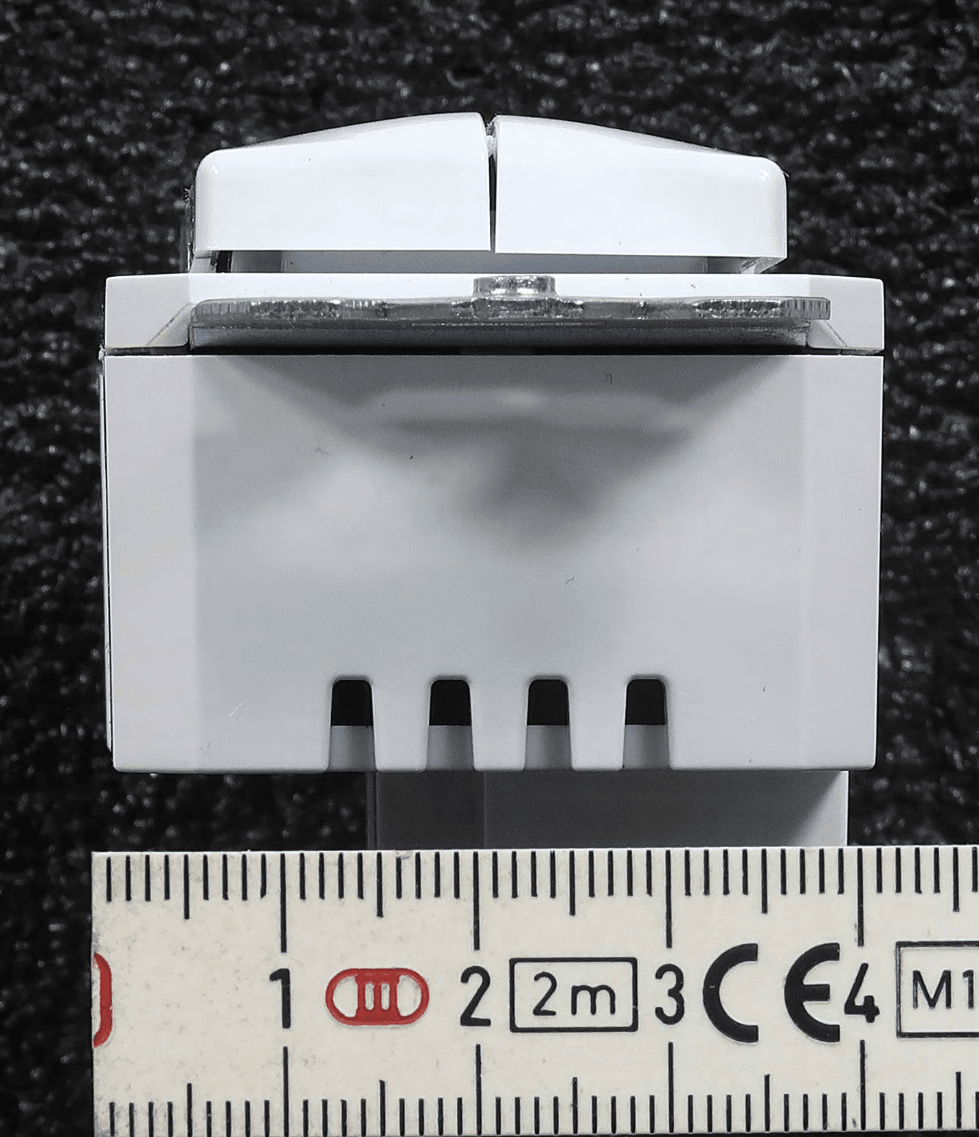
2AVRY-SWX0001
Jun 11, 2020Wireless line powered and battery powered wall switch
Equipment Class
DTS - Digital Transmission System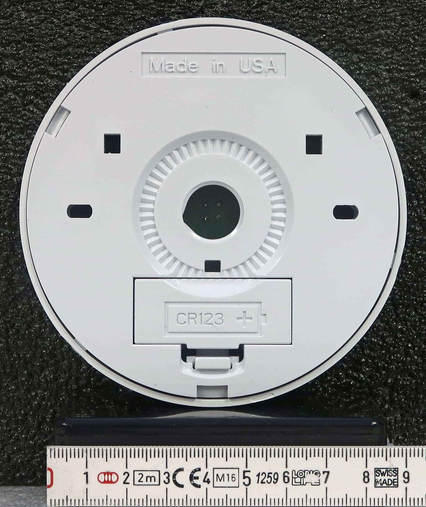
2AVRY-SWX0002
Jun 11, 2020Wireless Ceiling Mount Sensor
Equipment Class
DTS - Digital Transmission System