2AVTOTWS80TWS Earbud
Star Technology Industrial CO.,Limited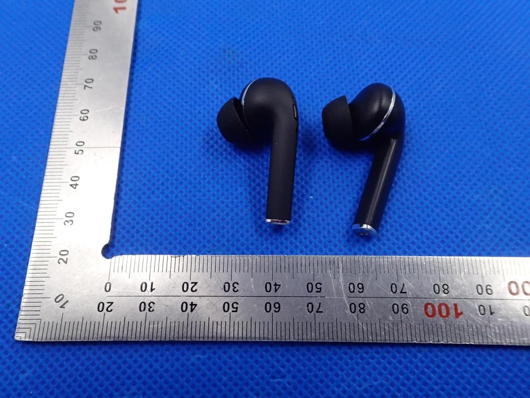
Click to zoom
Application Details
- Equipment Class
- DSS - Part 15 Spread Spectrum Transmitter
- Date of Grant
- Mar 12, 2020
- Application Purpose
- Original Equipment
- Date of Application
- Mar 12, 2020
- Equipment Note
- TWS Earbud
- Frequency Range
- 2402.00000000 - 2480.00000000
- Country
- China
Documents & Files
Document Text
Text extracted from the exhibit documents filed with the FCC. Open a document above to read the original.
Users Manual
对耳无线立体声 蓝牙耳机 使用指南 True Wireless Stereo Earbuds Bluetooth Earphone User Manual Pairing 1.Auto Pairing Take out the left and right earphone form charging compartment, The earphones will be automatically on and paring. When pairing successfully, the left earphone will flash red and blue alternately and the right earphone light will go out. When auto-pairing failed, or dual earphone disconnected. Press the power button on left and right earphone, to make the earbuds off and on again, the left and right earphone will be connected manually. * If putting the earbuds back to the charging case or pairing the earbuds by buttons, neither way is ok to make the earbuds pairing, please long press the buttons for about 10 seconds, to force the earbuds off and on again. (some kinds of bluetooth solutions support this kind of operation) 2.Non-automatically earbuds pairing ①.Do above operation 1 or 2 to pair left and right earphone. ②.Open Mobile Phone Bluetooth settings. ③.Search Bluetooth name “SY-TWS1”, click it to connect. 3.Earphones and Mobile Phone Pairing ①.Long press the button of the right earphone ②.Open Mobile Phone Bluetooth settings. ③.Search Bluetooth name “SY-TWS1”, click it to connect. 4.Right Earphone and Mobile Phone Pairing ①.Long press the of the left earphone ②.Open Mobile Phone Bluetooth settings. ③.Search Bluetooth name “SY-TWS1”, click it to connect. button 5.Left Earphone and Mobile Phone Pairing Precautions The product needs to be charged with a premium charging cable, and the Micro USB cable is connected to a 5V(1A-2A) power adapter or a 5V (1A-2A) car charger. Recommending to use a power adapter below 2A. It needs about 1~2 hours to do the fully charge. ▪ Please pay attention to the use of high-quality charger or computer port charging for the product, must not use cheap and poor quality charger. ▪ Bluetooth Earphones are affected by the environment and connection distance. Please do not use them in environments with strong electromagnetic interference and radiation. ▪ Please do not put the Bluetooth earphone in the water or beat it, which will cause damage to the product. ▪ If the Bluetooth Earphone is not used for a long time, please charge it monthly to prevent it from starting due to lack of power. ▪ We may upgrade the software, hardware or appearance of this product without notice, please refer to the actual product. Frequently asked questions Why bluetooth earbuds can not turn on? ①. You can check if earbuds is with power or not ? if not, please fully charge it before turning it on. ②. Please long press the power on /off button.(the detailed operation , please refer to the manual.) Why bluetooth earbuds signal is not unstable? ①. Restart the bluetooth earbuds . . Please kindly check the compatibility and calling communication quality of the mobile phone. . Please confirm if the distance between earbuds and phone is too far or there are interference surrounded. If too far or there are interference ,the signal will be unstable. .Please don’t stay in the signal reflective environment. Why the bluetooth earbuds noise is so big? ①.Please kindly check the mobile phone’s noise suppression function. ②.Please kindly check if the bluetooth earbuds and mobiles phone’s distance is too far .If too far, please shorten it and try it again. ③.Please kindly confirm if there is an electromagnetic radiation surrounding environment. ② ③ ④ ①While charging, the charging compartment indicator flash red light. After fully charged, the light is keeping red. Press charging compartment button, when the indicator light blue, it means the charging case has sufficient power. If the blue light flashes slowly, It means the battery is low. When no power, the light will be off. ② 3.Charging Compartment Indicator State Bluetooth Turn on Bluetooth SY-TWS1 Bluetooth Earphone (2 PCS) Earphone Charging Compartment USB Charging Cable User Manual Beautiful Box Spare Silicone Earpads Packing details Please double check and confirm the charging compartment has sufficient power, then put the earphones into the correct position for charging. 2. Charge for Earphones Product Specification Bluetooth Version: 5.0 Power Input: DC 5V Earphone Working Time: About 2 hours Earphone Charging Time: About 1 hours Charge Time: About 2 ~ 3h Earphone battery capacity: 35mAh Charging Case battery capacity: 400mAh Support Protocol: HSP/HFP/A2DP/AVRCP Sensitivity: 108+/-5dB Frequency response: 20-20000Hz Impedance: 32 ohms Why the bluetooth earbuds can’t hear voice? ①.Please kindly check if the bluetooth earbuds is on mute status. ②.Please kindly check if bluetooth earbuds and phone are connected well. ③.Then confirm if the distance between earbuds and phone is too far or there are interference surrounded. How to charge? ①.Use the original USB charging cable, one side connect with earbuds, the other side connect with PC/Table/power bank. ②.Usually it will takes about 2~3 hours to charge. How to contact with computer? ①.First check if the computer with bluetooth function or not?,if not ,please buy a bluetooth adaptor before connection. ②.Install bluetooth driver into computer. If the bluetooth earbuds can be upgraded? ①.Normally bluetooth can not be upgraded, as the bluetooth chipset is ROM chipset. ②.When upgraded, please operate follow the guideline, otherwise it may be failed on upgrading. How to connect earbuds with bluetooth devices(smart phones/tablet)? ①.1.Power on, the earbuds with enter into pairing mode. ②.Turn on the bluetooth function on bluetooth device ,search the earbuds model name and click it to pairing. ③.If need input the password, please input 1234 or 0000. SY-TWS1 正面 规格:35 x 11 cm 在播放音乐状态下,单击左或右耳的多功能键播放/暂停音乐。 4. 播放/暂停音乐 多功能键 双耳配对:长按左和右耳的多功能键 3 秒,开关机 单耳配对:长按左或右耳的多功能键 3 秒开机,进入单耳配对,长按 3 秒关机。(开机时 红蓝灯交替闪烁,关机时红灯闪烁后熄灭。) 来电状态下,单击左或右耳的多功能键接通电话。 通话状态下,单击左或右耳的多功能键挂断电话。 2. 接听/挂断电话 来电状态下,长按左或右耳的多功能键拒接电话。 回拔电话,三击右耳的多功能键,回拔最后一个电话;三击左耳的多功能键,打开语音 助手。 3. 拒接/电话回拔 三击多功能键, 回拔最后一个电话. 右耳的 在播放音乐状态下,双击左耳的多功能键实现上一曲功能;双击右耳的多功能键实现下 一曲功能。 5.…
Text truncated - open the document above for the full version.
Cover Letter(s)
Star Technology Industrial Co., Limited Mar. 09, 2020 Federal Communication Commission Authorization and Evaluation Division FCC ID: 2AVTOTWS80 Re: Confidentiality Request Pursuant to Sections 0.457 and 0.459 of the Commission’s Rules, the applicant hereby requests confidential treatment of information applied this application as outlined below: 1: Block Diagram 2: Schematics 3: Operational Description The above materials contain trade secrets and proprietary information not customarily released to the public. The public disclosure of these matters might be harmful to the applicant and provide unjustified benefits to its competitors. The Applicant understands that pursuant to Rules 0.457, disclosure of this Application and all accompanying documentation will not be made before the date of the Grant for this application. Sincerely, Star Technology Industrial Co., Limited Contact person: Lily Huang
External Photos
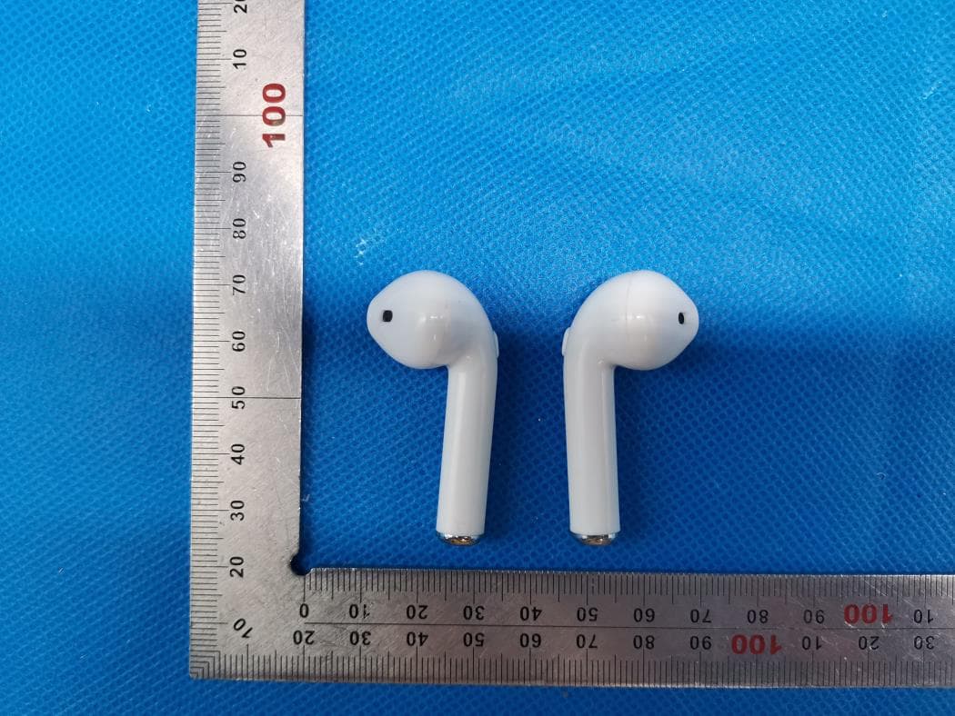
External Photos ALL VIEW OF EUT TOP VIEW OF EUT BOTTOM VIEW OF EUT FRONT VIEW OF EUT BACK VIEW OF EUT LEFT VIEW OF EUT RIGHT VIEW OF EUT
ID Label/Location Info
FCC ID Label Location FCC ID:2AVTOTWS80
Internal Photos
Internal Photos OPEN VIEW OF EUT-Left INTERNAL VIEW-1 OF EUT Antenna INTERNAL VIEW-2 OF EUT VIEW OF BATTERY OPEN VIEW OF EUT–Right INTERNAL VIEW-1 OF EUT Antenna INTERNAL VIEW-2 OF EUT VIEW OF BATTERY
Test Report
Page 1 of 59 FCC Test Report Report No.: AGC00806200103FE03 FCC ID : 2AVTOTWS80 APPLICATION PURPOSE : Original Equipment PRODUCT DESIGNATION : TWS Earbud BRAND NAME : N/A MODEL NAME : TWS80, EB5543 APPLICANT : Star Technology Industrial Co., Limited DATE OF ISSUE : Mar. 09, 2020 STANDARD(S) : FCC Part 15.247 REPORT VERSION : V1.0 Attestation of Global Compliance (Shenzhen) Co., Ltd CAUTION: This report shall not be reproduced except in full without the written permission of the test laboratory and shall not be quoted out of context. Report No.: AGC00806200103FE03 Page 2 of 59 REPORT REVISE RECORD Report Version Revise Time Issued Date Valid Version Notes V1.0 / Mar. 09, 2020 Valid Initial Release Report No.: AGC00806200103FE03 Page 3 of 59 TABLE OF CONTENTS 1. VERIFICATION OF CONFORMITY ............................................................................................................... 5 2. GENERAL INFORMATION ............................................................................................................................ 6 2.1. PRODUCT DESCRIPTION ..................................................................................................................... 6 2.2. TABLE OF CARRIER FREQUENCYS ..................................................................................................... 6 2.3. RECEIVER INPUT BANDWIDTH ............................................................................................................ 7 2.4. EXAMPLE OF A HOPPING SEQUENCY IN DATA MODE ....................................................................... 7 2.5. EQUALLY AVERAGE USE OF FREQUENCIES AND BEHAVIOUR ........................................................ 7 2.6. RELATED SUBMITTAL(S) / GRANT (S) .................................................................................................. 8 2.7. TEST METHODOLOGY .......................................................................................................................... 8 2.8. SPECIAL ACCESSORIES ....................................................................................................................... 8 2.9. EQUIPMENT MODIFICATIONS .............................................................................................................. 8 3. MEASUREMENT UNCERTAINTY ................................................................................................................. 9 4. DESCRIPTION OF TEST MODES ............................................................................................................... 10 5. SYSTEM TEST CONFIGURATION ............................................................................................................. 11 5.1. CONFIGURATION OF EUT SYSTEM .................................................................................................... 11 5.2 EQUIPMENT USED IN TESTED SYSTEM .............................................................................................. 11 5.3. SUMMARY OF TEST RESULTS ............................................................................................................. 11 6. TEST FACILITY ........................................................................................................................................... 12 7. PEAK OUTPUT POWER ............................................................................................................................. 13 7.1. MEASUREMENT PROCEDURE ........................................................................................................... 13 7.2. TEST SET-UP (BLOCK DIAGRAM OF CONFIGURATION) ................................................................... 13 7.3. LIMITS AND MEASUREMENT RESULT ............................................................................................... 14 8. 20DB BANDWIDTH ..................................................................................................................................... 18 8.1. MEASUREMENT PROCEDURE ........................................................................................................... 18 8.2. TEST SET-UP (BLOCK DIAGRAM OF CONFIGURATION) ................................................................... 18 8.3. LIMITS AND MEASUREMENT RESULTS ............................................................................................. 18 9. CONDUCTED SPURIOUS EMISSION ........................................................................................................ 23 9.1. MEASUREMENT PROCEDURE ........................................................................................................... 23 9.2. TEST SET-UP (BLOCK DIAGRAM OF CONFIGURATION) ................................................................... 23 9.3. MEASUREMENT EQUIPMENT USED .................................................................................................. 23 Report No.: AGC00806200103FE03 Page 4 of 59 9.4. LIMITS AND MEASUREMENT RESULT ............................................................................................... 23 10. RADIATED EMISSION ............................................................................................................................... 31 10.1. MEASUREMENT PROCEDURE ......................................................................................................... 31 10.2. TEST SETUP ....................................................................................................................................... 33 10.3. LIMITS AND MEASUREMENT RESULT ............................................................................................. 34 10.4. TEST RESULT ..................................................................................................................................... 34 11. NUMBER OF HOPPING FREQUENCY ..................................................................................................... 44 11.1. MEASUREMENT PROCEDURE ....…
Text truncated - open the document above for the full version.
Test Report
Report No.: AGC00806200103FE03 Page 39 of 59 EUT TWS Earbud Model Name TWS80 Temperature 25°C Relative Humidity 55.4% Pressure 960hPa Test Voltage Normal Voltage Test Mode Mode 3 Antenna Horizontal FrequencyMeter ReadingFactor Emission LevelLimitsMargin (MHz)(dBμV) (dB)(dBμV/m)(dBμV/m)(dB) 4960.02243.80 74.00 -30.20 peak 4960.02239.39 54.00 -14.61 AVG 7440.03343.56 74.00 -30.44 peak 7440.03339.76 54.00 -14.24 AVG Value Type 43.58 0.22 39.17 0.22 40.92 2.64 37.12 2.64 Remark: Factor = Antenna Factor + Cable Loss – Pre-amplifier. EUT TWS Earbud Model Name TWS80 Temperature 25°C Relative Humidity 55.4% Pressure 960hPa Test Voltage Normal Voltage Test Mode Mode 3 Antenna Vertical FrequencyMeter ReadingFactor Emission LevelLimitsMargin (MHz)(dBμV) (dB)(dBμV/m)(dBμV/m)(dB) 4960.02242.66 74.00 -31.34 peak 4960.02238.78 54.00 -15.22 AVG 7440.03343.40 74.00 -30.60 peak 7440.03339.69 54.00 -14.31 AVG Value Type 42.44 0.22 38.56 0.22 40.76 2.64 37.05 2.64 Remark: Factor = Antenna Factor + Cable Loss – Pre-amplifier. RESULT: PASS Note: Other emissions from 1G to 25 GHz are considered as ambient noise. No recording in the test report. Factor = Antenna Factor + Cable loss - Amplifier gain, Over=Measure-Limit. The “Factor” value can be calculated automatically by software of measurement system. All test modes had been tested. The GFSK modulation is the worst case and recorded in the report. Report No.: AGC00806200103FE03 Page 40 of 59 TEST RESULT FOR RESTRICTED BANDS REQUIREMENTS EUT TWS Earbud Model Name TWS80 Temperature 25°C Relative Humidity 55.4% Pressure 960hPa Test Voltage Normal Voltage Test Mode Mode 1 Antenna Horizontal PK AV RESULT: PASS Report No.: AGC00806200103FE03 Page 41 of 59 EUT TWS Earbud Model Name TWS80 Temperature 25°C Relative Humidity 55.4% Pressure 960hPa Test Voltage Normal Voltage Test Mode Mode 1 Antenna Vertical PK AV RESULT: PASS Report No.: AGC00806200103FE03 Page 42 of 59 EUT TWS Earbud Model Name TWS80 Temperature 25°C Relative Humidity 55.4% Pressure 960hPa Test Voltage Normal Voltage Test Mode Mode 3 Antenna Horizontal PK AV RESULT: PASS Report No.: AGC00806200103FE03 Page 43 of 59 EUT TWS Earbud Model Name TWS80 Temperature 25°C Relative Humidity 55.4% Pressure 960hPa Test Voltage Normal Voltage Test Mode Mode 3 Antenna Vertical PK AV RESULT: PASS Note: The factor had been edited in the “Input Correction” of the Spectrum Analyzer. So the Amplitude of test plots is equal to Reading level plus the Factor in dB. Use the A dB(μV) to represent the Amplitude. Use the F dB(μV/m) to represent the Field Strength. So A=F. All test modes had been pre-tested. The GFSK modulation is the worst case and recorded in the report. Report No.: AGC00806200103FE03 Page 44 of 59 11. NUMBER OF HOPPING FREQUENCY 11.1. MEASUREMENT PROCEDURE The EUT shall have its hopping function enabled. Use the following spectrum analyzer settings: 1. Span: The frequency band of operation. Depending on the number of channels the device supports, it may be necessary to divide the frequency range of operation across multiple spans, to allow the individual channels to be clearly seen. 2. RBW: To identify clearly the individual channels, set the RBW to less than 30% of the channel spacing or the 20 dB bandwidth, whichever is smaller. 3. VBW ≥ RBW. Sweep: Auto. Detector function: Peak. Trace: Max hold. 4. Allow the trace to stabilize. 11.2. TEST SETUP (BLOCK DIAGRAM OF CONFIGURATION) Same as described in section 8.2 11.3. MEASUREMENT EQUIPMENT USED The same as described in section 6 11.4. LIMITS AND MEASUREMENT RESULT TOTAL NO. OF HOPPING CHANNEL LIMIT (NO. OF CH) MEASUREMENT (NO. OF CH) RESULT >=15 79 PASS TEST PLOT FOR NO. OF TOTAL CHANNELS Note: The π /4-DQPSK modulation is the worst case and recorded in the report. Report No.: AGC00806200103FE03 Page 45 of 59 12. TIME OF OCCUPANCY (DWELL TIME) 12.1. MEASUREMENT PROCEDURE The EUT shall have its hopping function enabled. Use the following spectrum analyzer settings: 1. Span: Zero span, centered on a hopping channel. 2. RBW shall be≤channel spacing and where possible RBW should be set >> 1 / T, where T is the expected dwell time per channel. 3. Sweep: As necessary to capture the entire dwell time per hopping channel; where possible use a video trigger and trigger delay so that the transmitted signal starts a little to the right of the start of the plot. The trigger level might need slight adjustment to prevent triggering when the system hops on an adjacent channel; a second plot might be needed with a longer sweep time to show two successive hops on a channel. 4. Detector function: Peak. Trace: Max hold. 5. Use the marker-delta function to determine the transmit time per hop. 6. Repeat the measurement using a longer sweep time to determine the number of hops over the period specified in the requirements. The sweep time shall be equal to, or less than, the period specified in the requirements. Determine the number of hops over the sweep time and calculate the total number of hops in the period specified in the requirements, using the following equation: (Number of hops in the period specified in the requirements) = (number of hops on spectrum analyzer) × (period specified in the requirements / analyzer sweep time) 7. The average time of occupancy is calculated from the transmit time per hop multiplied by the number of hops in the period specified in the requirements. 12.2. TEST SETUP (BLOCK DIAGRAM OF CONFIGURATION) Same as described in section 8.2 12.3. MEASUREMENT EQUIPMENT USED The same as described in section 6 12.4. LIMITS AND MEASUREMENT RESULT Channel Time of Pulse for DH5 (ms) Number of hops in the period specified in the requirements Sweep Time (ms) Limit (ms) Low 2.917 28*4 326.704 400 Middle 2.933 27*4 316.764 400 High 2.933 22*4 258.104 400 Note: The π /4-DQPSK modulation is the worst case and recorded in the report. Report No.: AGC00806200103FE03 Page 46 of 59 TEST PLOT OF LOW CHANNEL Report No.: AGC00806200103FE03 Page 47 of 59 TEST PLOT OF MIDDLE …
Text truncated - open the document above for the full version.
Test Setup Photos
Test Setup Photos RADIATED EMISSION TEST SETUP BELOW 1GHZ RADIATED EMISSION TEST SETUP ABOVE 1GHZ CONDUCTED TEST SETUP
Contact Information
Applicant
Lily Huang
Test Firm
Attestation of Global Compliance (Shenzhen) Co., LDoris Li
[email protected]+86-755-25234088
Technical Specifications
| # | Rule Parts | Frequency Range | Power Output |
|---|---|---|---|
| 1 | 15C | 2.40 GHz - 2.48 GHz | 800.00 µW |
Other Applications from Star Technology Industrial CO.,Limited
2AVTOTWS06
May 19, 2020TWS Earbud with Bluetooth
Equipment Class
DSS - Part 15 Spread Spectrum Transmitter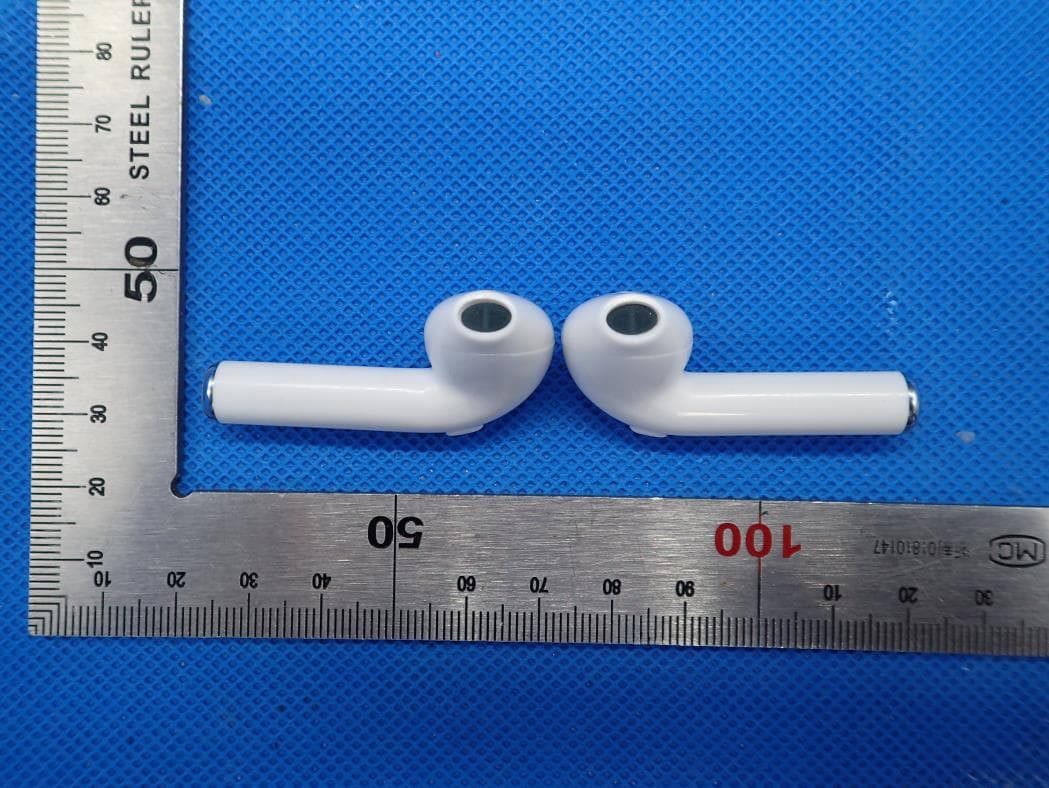
2AVTOTWS06S
Mar 18, 2020TWS Earbud
Equipment Class
DSS - Part 15 Spread Spectrum Transmitter