2AVTT-XR50A2.4G WIFI module
Shenzhen Jixin intelligence Co., Ltd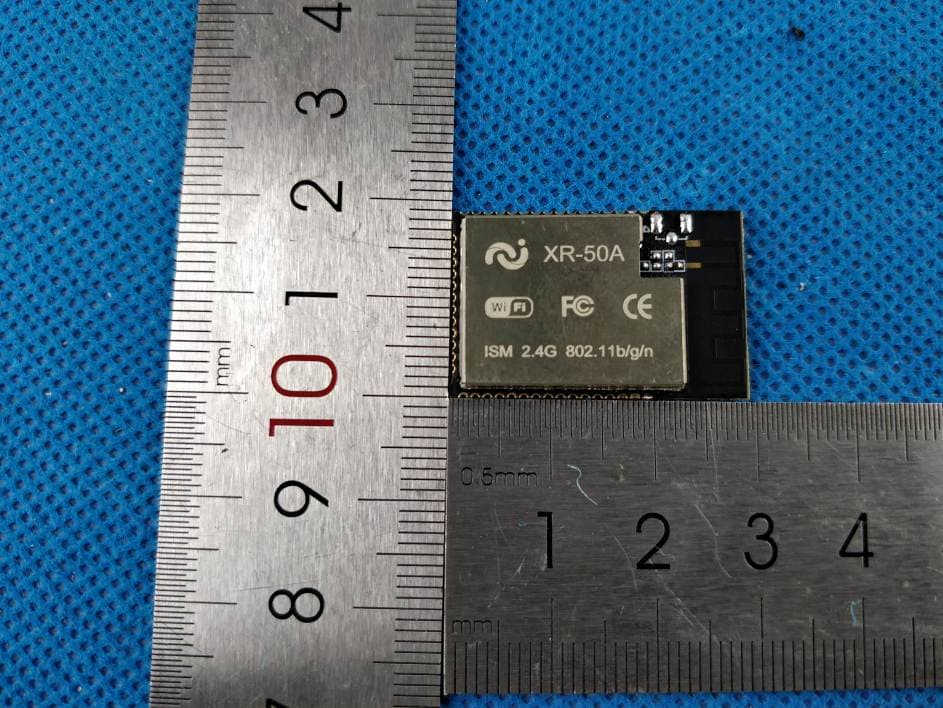
Click to zoom
Application Details
- Equipment Class
- DTS - Digital Transmission System
- Date of Grant
- Jun 29, 2020
- Application Purpose
- Original Equipment
- Date of Application
- Jun 29, 2020
- Equipment Note
- 2.4G WIFI module
- Frequency Range
- 2412.00000000 - 2462.00000000
- Country
- China
Documents & Files
Document Text
Text extracted from the exhibit documents filed with the FCC. Open a document above to read the original.
Users Manual
XR‐50A 1. Preambles The XR‐50A WiFi module was developed for image acquisition, voice playback and recognition, and wireless transmission applications. It integrates high performance WLAN subsystem with WiFi MAC/BB/RF/PA/LNA unit; Integrates high sample rate and very low noise Audio subsystem; integrates high‐resolution image acquisition subsystem, support hardware JPEG image encoding; integrated advantage power management unit, support ultra‐low power consumption, has a variety of sleep modes and fast wake‐up mechanism; Integrates hardware encryption engine to support AES/DES/3DES/SHA/MD5/CRC etc.; Integrates rich peripheral interfaces, such as I2S, SDIO, CSI, UART. XR‐50A WiFi module supports standard IEEE802.11 b/g/n protocol, supports RTOS, with a complete TCP/IP protocol stack. Users can use the module to add networking capabilities to existing devices, or can use it as a master design wireless network product, XR808 can be started directly from external flash memory, the on‐chip high‐speed buffer memory helps improve system performance and reduce RAM requirements. The core processor functional block diagram is shown below, 2.Features • IEEE 802.11b/g/n, 1x1 SISO 2.4GHz • Built‐in ARM Cortex‐M4F 32bit MCU with main frequency up to 384MHz, support RTOS • Built‐in 416KB SRAM , 160KB ROM and 4M PSRAM • Support external Flash and eXecute In Place(XIP) • 8 shared universal DMA channels • Built‐in 8‐way 12bit resolution SAR type AD converter • Integrated WiFi MAC/ BB/RF/PA/LNA • Support WEP, WPA/WPA2, WPS2.0 • Support UART/GPIO/ADC/PWM/I2C/I2S interface • Support AES/DES/3DES/SHA/MD5/CRC encryption engine • Support STA/AP/STA+AP mode • Support Smart Config/AirKiss(WeChat) One‐click distribution network • Support Local firmware upgrade using UART and remote upgrade (FOTA) • Has universal and friendly AT command set • Support secondary development, support Windows, Linux development environment • Integrated audio subsystem, including a digital microphone controller with voice input sway, one 24‐bit audio DAC channel with 8KHz to 192KHz sampling rate, one 24‐bit audio ADC channel for microphone input with 8KHz to 48KHz sampling rate, one 24‐bit audio ADC channel for line‐in interface, supporting sample rates from 8KHz to 48KHz • Integrated video subsystem (Video), support JPEG, YUV encoding mode, support nv12 input format in offline encoding mode, support configurable picture resolution, minimum picture resolution: 32x32, maximum picture resolution: 1920x1088 • Onboard 2dBi PCB antenna Federal Communication Commission Statement (FCC, U.S.) This equipment has been tested and found to comply with the limits for a Class B digital device, pursuant to Part 15 of the FCC Rules. These limits are designed to provide reasonable protection against harmful interference in a residential installation. This equipment generates, uses and can radiate radio frequency energy and, if not installed and used in accordance with the instructions, may cause harmful interference to radio communications. However, there is no guarantee that interference will not occur in a particular installation. If this equipment does cause harmful interference to radio or television reception, which can be determined by turning the equipment off and on, the user is encouraged to try to correct the interference by one of the following measures: -Reorient or relocate the receiving antenna. -Increase the separation between the equipment and receiver. -Connect the equipment into an outlet on a circuit different from that to which the receiver is connected. -Consult the dealer or an experienced radio/TV technician for help. This device complies with Part 15 of the FCC Rules. Operation is subject to the following two conditions: (1) This device may not cause harmful interference, and (2) this device must accept any interference received, including interference that may cause undesired operation. FCC Caution: Any changes or modifications not expressly approved by the party responsible for compliance could void the user's authority to operate this equipment. IMPORTANT NOTES Co-location warning: This transmitter must not be c o-located or operating in conjunction with any other antenna or transmitter. OEM integration instructions: This device is intended only for OEM integrators under the following conditions: The transmitter module may not be co-located with any other transmitter or antenna. The module shall be only used with the external antenna(s) that has been originally tested and certified with this module. As long as the conditions above are met, further transmitter tes t will not be required. However, the OEM integrator is still responsible for testing their end-product for any additional compliance requirements required with this module installed (for example, digital device emissions, PC peripheral requirements, etc.). 1) The antenna must be installed such that 20 cm is maintained between the antenna and users, and 2) This device and its antenna(s) must not be co‐located with any other transmitters except in accordance with FCC multi‐transmitter product procedures. Referring to the multi‐transmitter policy, multiple‐transmitter(s) and module(s) can be operated simultaneously without C2P. 3) For all products market in US, OEM has to limit the operation channels in CH1 to CH11 for 2.4G band by supplied firmware programming tool. OEM shall not supply any tool or info to the end‐user regarding to Regulatory Domain change. Validity of using the module certification: In the event that these conditions cannot be met (for example certain laptop configurations or co-location with another transmit ter), then the FCC authorization for this module in combination with the host equipment is no longer considered valid and the FCC ID of the module cannot be used on the final product. In these c ircumstances, the OEM integrator will be res ponsible for re-evaluating the end product (including the transmitter) and obtaining a separate FCC authoriza…
Text truncated - open the document above for the full version.
Cover Letter(s)
Shenzhen Jixin intelligence Co., Ltd {June 29, 2020} Single Modular Approval Request Letter Date: 2020-06-29 FCC ID: 2AVTT-XR50A Type of Equipment: DTS The following requirements according to FCC Part 15.212 are met: 1. “The modular transmitter must have its own RF shielding.”: Answer: The module has its own RF shield 2. “The modular transmitter must have buffered modulation/data inputs.”: Answer: The module has data transmission function and supports 2.4GWiFi function. 3. “The modular transmitter must have its own power supply regulation.”: Answer: Module with power regulation and support for DC 3.3V input 4. “The modular transmitter must comply with the antenna requirements of section 15.203 and 15.204(C).”: Answer: The module meets the antenna requirements of sections 15.203 and 15.204(c) Shenzhen Jixin intelligence Co., Ltd 5. “The modular transmitter must be tested in a stand-alone configuration”: Answer: The module has been tested in a standalone configuration, see report for details} 6. “The modular transmitter must be labeled with its own FCC ID number.”: Answer: The module has its own FCC ID number. See the label for details. 7. “The modular transmitter must comply with any specific rule or operating requirements applicable to the transmitter and the manufacturer must provide adequate instructions along with the module to explain any such requirements.”: Answer:The module meets any specific rules or operational requirements applicable to the transmitter} 8. “The modular transmitter must comply with any applicable RF exposure requirements.”: Answer:The module complies with any applicable RF exposure requirements, as detailed in the instructions.} Please contact me if you have any further questions. Regards, Signature: Name: Huabin Fu Title: CEO Company: Shenzhen Jixin intelligence Co., Ltd
External Photos
- Page 1 of 2 - Report No.: MTi19111507-13E1-1 Tel:(86-755)88850135 Fax: (86-755) 88850136 Web: http://www.mtitest.com E-mail: [email protected] Address: No.102A & 302A, East Block, Hengfang Industrial Park, Xingye Road, Xixiang, Bao'an District, Shenzhen, Guangdong, China APPENDIX 1: EUT PHOTO Photo 1 (For model XR-50A) Photo 2
ID Label/Location Info
SIZE:10mm*3mm FCC ID :2AVTT-XR50A
Internal Photos
- Page 2 of 2 - Report No.: MTi19111507-13E1-1 Tel:(86-755)88850135 Fax: (86-755) 88850136 Web: http://www.mtitest.com E-mail: [email protected] Address: No.102A & 302A, East Block, Hengfang Industrial Park, Xingye Road, Xixiang, Bao'an District, Shenzhen, Guangdong, China Photo 3 ----END OF REPORT---- WiFi Antenna
Operational Description
version01 Shenzhen Jixin intelligence Co., Ltd Declaration concerning Antenna Specification It is hereby declared that the product Model No.: XR-50A FCC ID: 2AVTT-XR50A fulfills the requirement in FCC test relating to the antenna type. The device specified above confirms to the FCC recommendations for Internal Antenna antenna type(s) described below: Model No. of antenna: N/A Type of antenna: PCB Antenna Gain of the antenna: 2 dBi Frequency range: 802.11b/g/n20:2412~2462 MHz The mounting of the antenna is fixed to the radio module and no other antenna should be used. Company name: Shenzhen Jixin intelligence Co., Ltd Address: A505 Room, Business Building, Suojia Science Park, Xixiang, Baoan District, Shenzhen, China City: Shenzhen ZIP / Postal code: N/A Country: China Contact: Huabin Fu Date: 21/04/2020 Signature:
RF Exposure Info
This test report is valid for the tested samples only. It cannot be reproduced except in full without prior written consent of Shenzhen Microtest Co., Ltd. Tel:(86-755)88850135 Fax: (86-755) 88850136 Web: http://www.mtitest.com E-mail: [email protected] Address: No.102A & 302A, East Block, Hengfang Industrial Park, Xingye Road, Xixiang, Bao'an District, Shenzhen, Guangdong, China MPE REPORT FCC ID: 2AVTT-XR50A Date of issue: June 28, 2020 Report number: MTi19111507-13E2 Sample description: 2.4G WIFI module Model(s): XR-50A Applicant: Shenzhen Jixin intelligence Co., Ltd Address: A505 Room, Business Building, Suojia Science Park, Xixiang, Baoan District, Shenzhen Date of test: Jan. 14, 2020 to June 28, 2020 Shenzhen Microtest Co., Ltd. http://www.mtitest.com - Page 2 of 4 - Report No.: MTi19111507-13E2 Tel:(86-755)88850135 Fax: (86-755) 88850136 Web: http://www.mtitest.com E-mail: [email protected] Address: No.102A & 302A, East Block, Hengfang Industrial Park, Xingye Road, Xixiang, Bao'an District, Shenzhen, Guangdong, China TEST RESULT CERTIFICATION Applicant’s name: Shenzhen Jixin intelligence Co., Ltd Address: A505 Room, Business Building, Suojia Science Park, Xixiang, Baoan District, Shenzhen Manufacture's name: Shenzhen Jixin intelligence Co., Ltd Address: A505 Room, Business Building, Suojia Science Park, Xixiang, Baoan District, Shenzhen Product name: 2.4G WIFI module Trademark: N/A Model and/or type reference . : XR-50A Serial model ........................... : N/A RF exposure procedures ....... : KDB 447498 D01 v06 This device described above has been tested by Shenzhen Microtest Co., Ltd and the test results show that the equipment under test (EUT) is in compliance with the FCC requirements. And it is applicable only to the tested sample identified in the report. Tested by: Danny Xu June 28, 2020 Reviewed by: Leo Su June 28, 2020 Approved by: Tom Xue June 28, 2020 - Page 3 of 4 - Report No.: MTi19111507-13E2 Tel:(86-755)88850135 Fax: (86-755) 88850136 Web: http://www.mtitest.com E-mail: [email protected] Address: No.102A & 302A, East Block, Hengfang Industrial Park, Xingye Road, Xixiang, Bao'an District, Shenzhen, Guangdong, China RF EXPOSURE EVALUATION According to FCC 1.1310: The criteria listed in the following table shall be used to evaluate the environment impact of human exposure to radio frequency (RF) Radiation as specified in §1.1307(b) Limits for Maximum Permissible Exposure (MPE) MPE Calculation Method Friis transmission formula: Pd= (Pout*G)\ (4*pi*R 2 ) Where Pd= Power density in mW/cm2 Pout=output power to antenna in mW G= Numeric gain of the antenna relative to isotropic antenna Pi=3.1415926 R= distance between observation point and center of the radiator in cm(20cm) Pd the limit of MPE, 1mW/cm2. If we know the maximum gain of the antenna and total power input to the antenna, through the calculation, we will know the distance where the MPE limit is reached. - Page 4 of 4 - Report No.: MTi19111507-13E2 Tel:(86-755)88850135 Fax: (86-755) 88850136 Web: http://www.mtitest.com E-mail: [email protected] Address: No.102A & 302A, East Block, Hengfang Industrial Park, Xingye Road, Xixiang, Bao'an District, Shenzhen, Guangdong, China Measurement Result WIFI: Operation Frequency: WIFI 802.11b/g/n HT20: 2412-2462MHz, Power density limited: 1mW/ cm 2 Antenna Type: PCB Antenna; Antenna gain: 2dBi R=20cm mW=10^(dBm/10) antenna gain Numeric=10^(dBi/10)= 10^(2/10)=1.58 Channel Freq. (MHz) modulation conducted power Tune- up power Max Antenna Evaluation result at 20cm Power density Limits (dBm) (dBm) tune-up power Gain Power density(mW/cm2 ) (mW/cm2) (dBm) (mW) Numeric 2412 802.11b 16.93 16±1 17 50.1187 1.58 0.01575 1 2437 16.60 16±1 17 50.1187 1.58 0.01575 1 2462 16.16 16±1 17 50.1187 1.58 0.01575 1 2412 802.11g 14.89 15±1 16 39.8107 1.58 0.01251 1 2437 14.84 15±1 16 39.8107 1.58 0.01251 1 2462 14.57 15±1 16 39.8107 1.58 0.01251 1 2412 802.11n H20 15.08 15±1 16 39.8107 1.58 0.01251 1 2437 14.97 15±1 16 39.8107 1.58 0.01251 1 2462 14.54 15±1 16 39.8107 1.58 0.01251 1 Conclusion: For the max result: 0.01575≤ 1.0 for 1g SAR, No SAR is required. ----END OF REPORT----
Test Report
This test report is valid for the tested samples only. It cannot be reproduced except in full without prior written consent of Shenzhen Microtest Co., Ltd. Tel:(86-755)88850135 Fax: (86-755) 88850136 Web: http://www.mtitest.com E-mail: [email protected] Address: No.102A & 302A, East Block, Hengfang Industrial Park, Xingye Road, Xixiang, Bao'an District, Shenzhen, Guangdong, China Test Report FCC ID: 2AVTT-XR50A Date of issue: June 28, 2020 Report number: MTi19111507-13E1 Sample description: 2.4G WIFI module Model(s): XR-50A Applicant: Shenzhen Jixin intelligence Co., Ltd Address: A505 Room, Business Building, Suojia Science Park, Xixiang, Baoan District, Shenzhen Date of test: Jan. 14, 2020 to June 28, 2020 Shenzhen Microtest Co., Ltd. http://www.mtitest.com - Page 2 of 52 - Report No.: MTi19111507-13E1 Tel:(86-755)88850135 Fax: (86-755) 88850136 Web: http://www.mtitest.com E-mail: [email protected] Address: No.102A & 302A, East Block, Hengfang Industrial Park, Xingye Road, Xixiang, Bao'an District, Shenzhen, Guangdong, China Table of Contents 1 GENERAL INFORMATION ...................................................................................................................................... 5 1.1 DESCRIPTION OF EUT ................................................................................................................................................... 5 1.2 OPERATION CHANNEL LIST .............................................................................................................................................. 6 1.3 TEST CHANNEL LIST ....................................................................................................................................................... 6 1.4 ANCILLARY EQUIPMENT LIST ........................................................................................................................................... 6 1.5 DESCRIPTION OF SUPPORT UNITS .................................................................................................................................... 6 2 SUMMARY OF TEST RESULTS ................................................................................................................................. 7 3 TEST FACILITIES AND ACCREDITATIONS .................................................................................................................. 8 3.1 TEST LABORATORY ........................................................................................................................................................ 8 3.2 ENVIRONMENTAL CONDITIONS ........................................................................................................................................ 8 3.3 MEASUREMENT UNCERTAINTY ........................................................................................................................................ 8 3.4 TEST SOFTWARE ........................................................................................................................................................... 8 4 EQUIPMENT LIST .................................................................................................................................................. 9 5 TEST RESULT ....................................................................................................................................................... 10 5.1 ANTENNA REQUIREMENT ............................................................................................................................................. 10 5.1.1 Standard requirement ....................................................................................................................................... 10 5.1.2 EUT antenna ..................................................................................................................................................... 10 5.2 PEAK OUTPUT POWER ................................................................................................................................................. 11 5.2.1 Limit .................................................................................................................................................................. 11 5.2.2 Test setup .......................................................................................................................................................... 11 5.2.3 Test procedure ................................................................................................................................................... 11 5.2.4 Test results ........................................................................................................................................................ 12 5.3 POWER SPECTRAL DENSITY ........................................................................................................................................... 13 5.3.1 Limit .................................................................................................................................................................. 13 5.3.2 Test setup .......................................................................................................................................................... 13 5.3.3 Test procedure ................................................................................................................................................... 13 5.3.4 Test results ........................................................................................................................................................ 14 5.4 CONDUCTED EMISSION ................................................................................................................................................ 17 5.4.1 Limits ................................................................................................................................................................. 17 …
Text truncated - open the document above for the full version.
Test Setup Photos
Model: XR-50A Radiated emission Conducted emission
Contact Information
Applicant
Huabin Fu(CEO)
Test Firm
Shenzhen Microtest Co., Ltd.Selby Liao
[email protected]0755-88850135-1193
Technical Specifications
| # | Rule Parts | Frequency Range | Power Output |
|---|---|---|---|
| 1 | 15C | 2.41 GHz - 2.46 GHz | 49.40 mW |
Other Applications from Shenzhen Jixin intelligence Co., Ltd
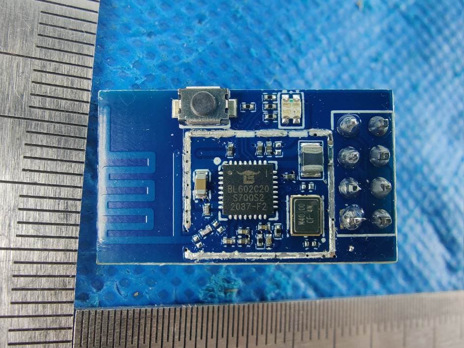
2AVTT-BL01S
Mar 02, 20212.4G WIFI/BT module
Equipment Class
DTS - Digital Transmission System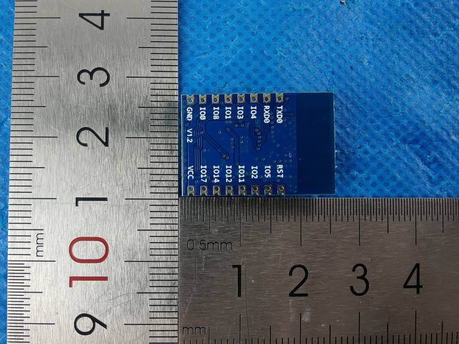
2AVTT-BL62B
Mar 02, 20212.4G WIFI/BT module
Equipment Class
DTS - Digital Transmission System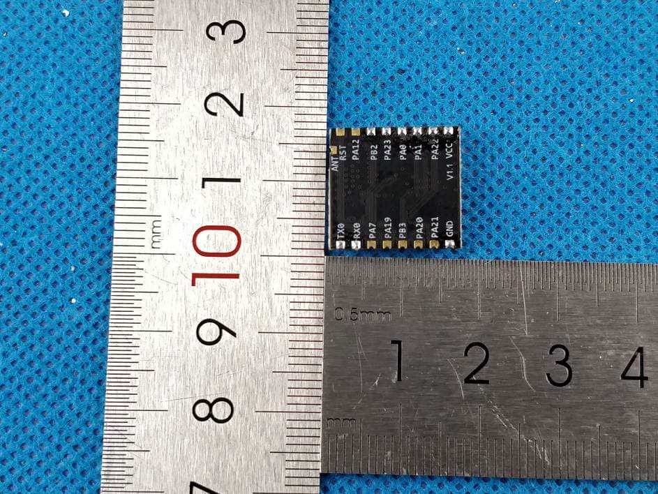
2AVTT-XR22A
Jun 29, 20202.4G WIFI module
Equipment Class
DTS - Digital Transmission System
2AVTT-XR21A
Jun 21, 20202.4G WIFI module
Equipment Class
DTS - Digital Transmission System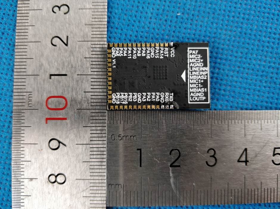
2AVTT-XR50B
Jun 01, 20202.4G WIFI module
Equipment Class
DTS - Digital Transmission System