2AVVF-ANSLMJL0619IntelliMove
Ansell Healthcare Products LLC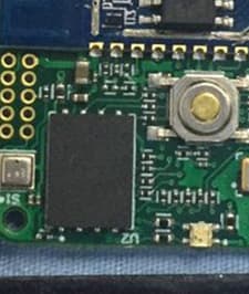
Click to zoom
Application Details
- Equipment Class
- DTS - Digital Transmission System
- Date of Grant
- Apr 07, 2020
- Application Purpose
- Original Equipment
- Date of Application
- Apr 07, 2020
- Equipment Note
- IntelliMove
- Frequency Range
- 2402.00000000 - 2480.00000000
- Country
- United States
Documents & Files
Document Text
Text extracted from the exhibit documents filed with the FCC. Open a document above to read the original.
Users Manual
What’s in the Box? 1. SmartGlove Device 2. SmartGlove Charging Station User Manual IntelliMove 3. Ansell Gloves (1 pair) Device operation x The pod is always on and collecting data except for the scenario wherein it is plugged into the docking station. x To start using the pod, take it out of the docking station and slide it into the back pocket of your glove or strap as shown in the image below x The LED on the pod must be blue indicating that the device is operating correctly. If the LED is red, it is indicative of low battery or an issue with the device health. In case of a red LED, return the device to the docking station and take a different one. x After completing the use for a day, take the pod out of the back pocket and put the device back in the docking station as shown in the figure. x The devices will come preprogrammed with the Wi-Fi credentials as provided by the customer. The credentials can be updated over the air if requested by the customer. The only requirement for updating the Wi-Fi credentials is that the device must be connected to a previous network to receive the updates over the air. x To pair the device to your Bluetooth network, go the mobile app as shown in the figure below and. Go to ‘More’> ‘BLE Devices’ and scan for the Bluetooth device. Please note that based on the login, the scanner will only show one specific device which is associated with the user login. This is to prevent a non-authorized user from connecting to a device and accessing data. x When the device id shows up, click on the connect button. The device will connect and start uploading data to the cloud in real time. The flow is shown in the images below Please note that the only condition for the data upload to the cloud is that the device to which the glove is paired to via Bluetooth (phone, tablet) must have an active internet connection . To check the user data, go to the Ansell mobile app or the web dashboard. Enter the login credentials provided. You can navigate the different widgets to check the data for different activities, in different forms and over different data and time ranges. Some examples are show in the images below Operational Constraints: x The device can only be connected to Wi-Fi when plugged in for charging and not while it is being worn. Only Bluetooth radio can be active while the device is being worn. x Simultaneous operation of Bluetooth and Wi-Fi is not possible by design. When the device is plugged in for charging, it will not be broadcasting Bluetooth identifiers as it can only connect to Wi-Fi in the plugged-in state Regulatory Compliance: FCC Device Usage Statement This device has been designed for two use cases. In the typical use case, there is a BLE radio which operates as the user is wearing the product. In this use case, the device meets the use requirements, as per 47 CFR § 2.1093, and can be operated as a portable device. In the second use case, there is a Wi-Fi radio which is only activated when the device is placed in the specific charging dock. In this use case, the device meets the use requirements as per 47 CFR § 2.1091, and is must be operated as a mobile device. While the WiFi radio is operating, as a mobile device, in the charging dock, users must maintain a separation distance of at least 20 centimeters between the transmitter's radiating structure(s) and the body of the user or nearby persons. While the BLE radio is operating, this device is safe for portable usage and a user can place the transmitter’s radiating structure(s) within 20 centimeters of their body. FCC - BLE RF Exposure Statement Users of this device when utilizing the BLE radio, note: This equipment has been tested and meets applicable limits for radio frequency (RF) exposure. FCC - WiFi RF Exposure Statement Users of this device when utilizing the WiFi radio, note: This equipment complies with the FCC radiation exposure limits set forth for an uncontrolled environment. This equipment should be installed and operated with a minimum distance of 20cm between the radiator and all persons. FCC Compliance Statement This device complies with part 15 of the FCC Rules. Operation is subject to the following two conditions: (1) this device may not cause harmful interference, and (2) this device must accept any interference received, including interference that may cause undesired operation. CAUTION: The grantee is not responsible for any changes or modifications not expressly approved by the party responsible for compliance. Such modifications could void the user’s authority to operate the equipment. NOTE: This equipment has been tested and found to comply with the limits for a Class B digital device, pursuant to part 15 of the FCC Rules. These limits are designed to provide reasonable protection against harmful interference in a residential installation. This equipment generates, uses, and can radiate radio frequency energy, and if not installed and used in accordance with the instructions, may cause harmful interference to radio communications. However, there is no guarantee that interference will not occur in a particular installation. If this equipment does cause harmful interference to radio or television reception, which can be determined by turning the equipment off and on, the user is encouraged to try to correct the interference by one or more of the following measures: – Reorient or relocate the receiving antenna. – Increase the separation between the equipment and receiver. – Connect the equipment into an outlet on a circuit different from that to which the receiver is connected. – Consult the dealer or an experienced radio/TV technician for help. ISED Device Usage Statement This device has been designed for two use cases. In the typical use case, there is a BLE radio which operates as the user is wearing the product. In this use case, the device meets the use requirements, of RSS-210, and can be operated as a body worn device. In the second use case, there is a WiFi radio which …
Text truncated - open the document above for the full version.
External Photos
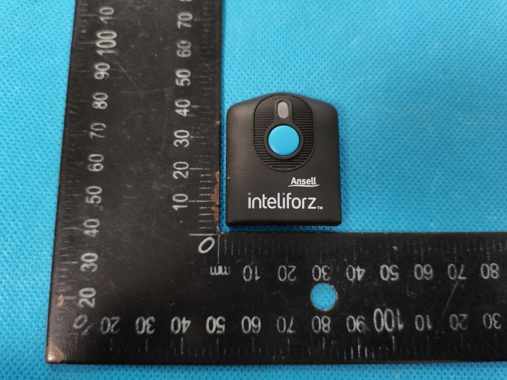
Report No.: W EXHIBI EUT View 1 EUT View 2 WTX20X030 T 2 - EUT 1 2 08166W T EXTER RNAL PH HOTOGR APHS Model FCC : ANSL0001 C Part 15.247 Report No.: W EUT View 3 EUT View 4 WTX20X030 3 4 08166W Model FCC : ANSL0001 C Part 15.247 Report No.: W EUT View 5 EUT View 6 WTX20X030 5 6 08166W Model FCC : ANSL0001 C Part 15.247 Report No.: W EUT View 7 WTX20X030 7 08166W Model FCC : ANSL0001 C Part 15.247
ID Label/Location Info
Report No.: W EXHIBI Proposed Specificatio n silk-screened Proposed WTX20X030 T 1 - PRO FCC ID La ns: Text is b d onto the EU Label Loca 08166W ODUCT L abel Forma black in colo UT or shall be ation on EU LABELIN at r and justifie e affixed at a UT FCC NG ed. Labels ar conspicuous ID Label Lo re printed in location on t cation indelible ink the EUT. Model FCC k on perman : ANSL0001 C Part 15.247 nent adhesivee
Internal Photos
Report No.: W EXHIBI EUT Housi n EUT Housi n WTX20X030 T 3 - EUT ng and Boar ng and Boar 08166W T INTER rd View 1 rd View 2 NAL PHO OTOGRA APHS Model FCC : ANSL0001 C Part 15.247 Report No.: W EUT Housin Solder Boa r WTX20X030 ng and Boar rd-Compone 08166W rd View 3 ent View 1 Model FCC : ANSL0001 C Part 15.247 Report No.: W Solder Boar Solder Boa r WTX20X030 rd-Compone rd-Compone 08166W ent View 2 ent View 3 Model FCC : ANSL0001 C Part 15.247 Report No.: W Antenna Vi WTX20X030 iew 08166W Bluetooth Antenna Model FCC : ANSL0001 C Part 15.247
RF Exposure Info
RF Exposure Requirements Product Description: IntelliMove Model No.: ANSL0001 FCC ID: 2AVVF-ANSLMJL0619 According to the KDB 447498 D01 v06 section 4.3.1, for 100 MHz to 6 GHz and test separation distances ≤ 50 mm, the 1-g and 10-g SAR test exclusion thresholds are determined by the following: [(max. power of channel, including tune-up tolerance, mW)/(min. test separation distance, mm)] · [√f(GHz)] ≤ 3.0 for 1-g SAR and ≤ 7.5 for 10-g extremity SAR, where - f(GHz) is the RF channel transmit frequency in GHz - Power and distance are rounded to the nearest mW and mm before calculation17 - The result is rounded to one decimal place for comparison Calculation Result: Tx frequency range: 2402-2480MHz Min. test separation distance: 5mm Maximum Conducted Output Power: -2.82dBm Tune-Up output power: -2dBm RF channel transmit frequency: 2480MHz Result: 0.20 Limit: 3.0 The exclusion thresholds is 0.20 < 3, so the transmitter complies with the RF exposure requirements and the SAR is not required.
Test Report
Model: ANSL0001 Report No.: WTX20X03008166W Page 1 of 37 FCC Part 15.247 FCC Part 15C Measurement and Test Report For Ansell 511 Westinghouse Rd, Pendleton, SC 29670, United States FCC ID: 2AVVF-ANSLMJL0619 FCC Rule(s): FCC Part 15.247 Product Description: IntelliMove Tested Model: ANSL0001 Report No.: WTX20X03008166W Sample Receipt Date: Mar.09, 2020 Tested Date: Mar.09, 2020 to Mar.13, 2020 Issued Date: Mar.13, 2020 Tested By: Mike Shi / Engineer Reviewed By: Lion Cai / RF Manager Approved & Authorized By: Silin Chen / Manager Prepared By: Shenzhen SEM Test Technology Co., Ltd. 1/F, Building A, Hongwei Industrial Park, Liuxian 2nd Road, Bao'an District, Shenzhen, P.R.C.(518101) Tel.: +86-755-33663308 Fax.: +86-755-33663309 Website: www.semtest.com.cn Note: This test report is limited to the above client company and the product model only. It may not be duplicated without prior permitted by Shenzhen SEM Test Technology Co., Ltd. Model: ANSL0001 Report No.: WTX20X03008166W Page 2 of 37 FCC Part 15.247 TABLE OF CONTENTS 1. GENERAL INFORMATION ................................................................................................................................... 4 1.1 PRODUCT DESCRIPTION FOR EQUIPMENT UNDER TEST (EUT) ............................................................................... 4 1.2 TEST STANDARDS ................................................................................................................................................... 5 1.3 TEST METHODOLOGY ............................................................................................................................................. 5 1.4 TEST FACILITY ....................................................................................................................................................... 5 1.5 EUT SETUP AND TEST MODE ................................................................................................................................. 6 1.6 MEASUREMENT UNCERTAINTY .............................................................................................................................. 7 1.7 TEST EQUIPMENT LIST AND DETAILS ..................................................................................................................... 8 2. SUMMARY OF TEST RESULTS ......................................................................................................................... 10 3. RF EXPOSURE ....................................................................................................................................................... 11 3.1 STANDARD APPLICABLE ....................................................................................................................................... 11 3.2 TEST RESULT........................................................................................................................................................ 11 4. ANTENNA REQUIREMENT ................................................................................................................................ 12 4.1 STANDARD APPLICABLE ....................................................................................................................................... 12 4.2 EVALUATION INFORMATION ................................................................................................................................ 12 5. POWER SPECTRAL DENSITY ........................................................................................................................... 13 5.1 STANDARD APPLICABLE ....................................................................................................................................... 13 5.2 TEST PROCEDURE ................................................................................................................................................. 13 5.3 SUMMARY OF TEST RESULTS/PLOTS .................................................................................................................... 13 6. DTS BANDWIDTH ................................................................................................................................................. 15 6.1 STANDARD APPLICABLE ....................................................................................................................................... 15 6.2 TEST PROCEDURE ................................................................................................................................................. 15 6.3 SUMMARY OF TEST RESULTS/PLOTS .................................................................................................................... 15 7. RF OUTPUT POWER ............................................................................................................................................ 17 7.1 STANDARD APPLICABLE ....................................................................................................................................... 17 7.2 TEST PROCEDURE ................................................................................................................................................. 17 7.3 SUMMARY OF TEST RESULTS/PLOTS .................................................................................................................... 17 8. FIELD STRENGTH OF SPURIOUS EMISSIONS ............................................................................................. 19 8.1 STANDARD APPLICABLE ....................................................................................................................................... 19 8.2 TEST PROCEDURE ................................................................................................................................................. 19 8.3 CORRECTED AMPLITUDE & MARGIN CALCULATION ............................................................................................ 20 8.4 SUMMARY O…
Text truncated - open the document above for the full version.
Test Setup Photos
Report No.: W EXHIBI Conducted Radiation E WTX20X030 T 4 - TES Emission Te Emission Tes 08166W ST SETUP est Setup st Setup (Belo P PHOTO ow 30MHz) OGRAPH HS Model FCC : ANSL0001 C Part 15.247 Report No.: W Radiation E WTX20X030 Emission Tes 08166W st Setup (30M MHz to 1GHz z) Model FCC : ANSL0001 C Part 15.247 Report No.: W Radiation E Radiation E WTX20X030 Emission Tes Emission Tes 08166W st Setup (1GH st Setup (Abo Hz to 18GHz ove 18GHz) z) Model FCC : ANSL0001 C Part 15.247
Contact Information
Applicant
James Thompson(Associate Director for App and Physical Testing)
Test Firm
Waltek Testing Group (Shenzhen) Co., Ltd.Jandy So
Technical Specifications
| # | Rule Parts | Frequency Range | Power Output |
|---|---|---|---|
| 1 | 15C | 2.40 GHz - 2.48 GHz | 1.00 mW |
Other Applications from Ansell Healthcare Products LLC
2AVVF-22-134
Nov 21, 2022Pod 2.3
Equipment Class
NII - Unlicensed National Information Infrastructure TX