2AVWKWSU30KWWireless Charger Secondary Pad
DELTA ENERGY SYSTEMS (GERMANY) GMBH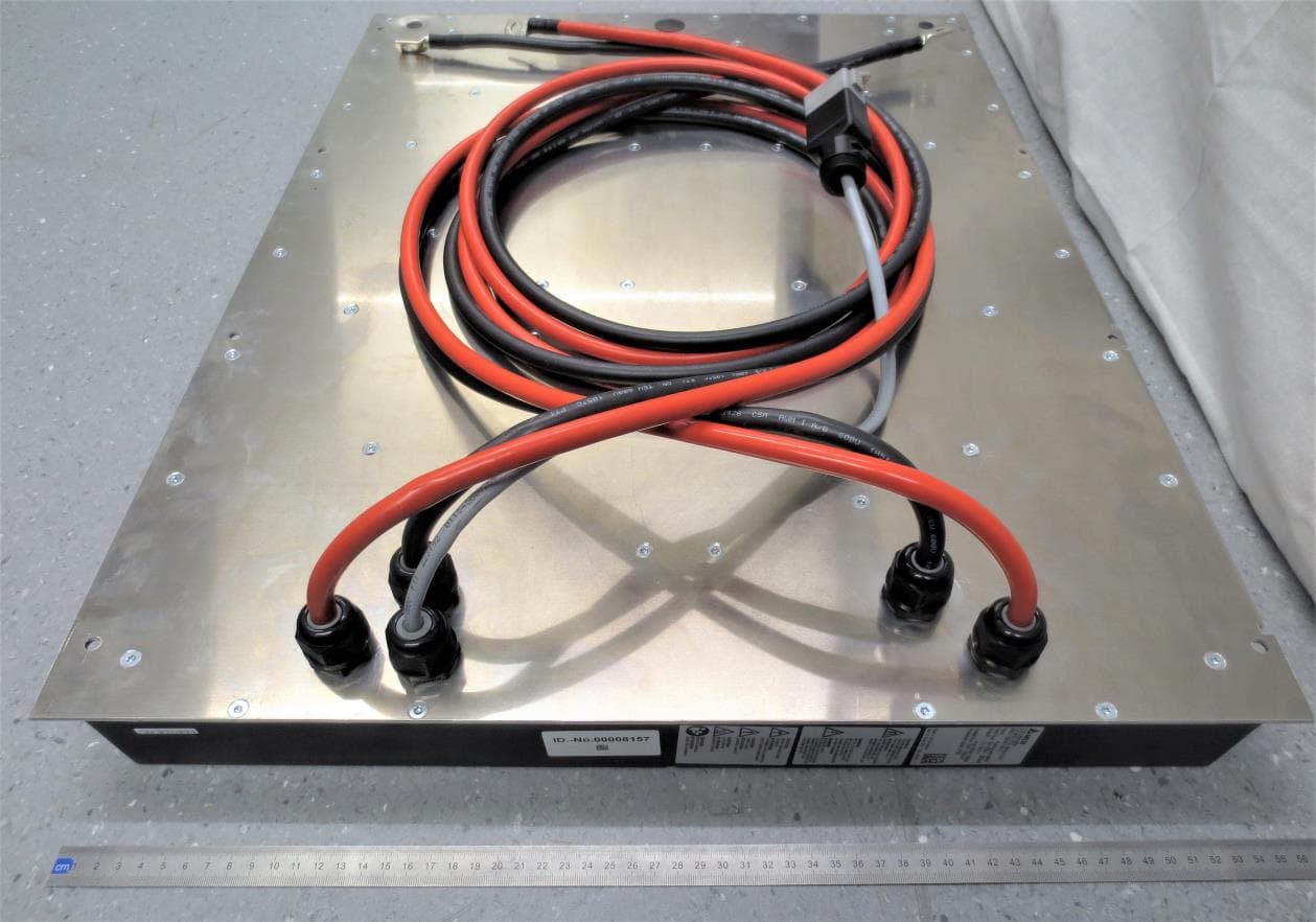
Click to zoom
Application Details
- Equipment Class
- DXX - Part 15 Low Power Communication Device Transmitter
- Date of Grant
- Nov 30, 2023
- Application Purpose
- Original Equipment
- Date of Application
- Nov 30, 2023
- Equipment Note
- Wireless Charger Secondary Pad
- Frequency Range
- 13.56000000 - 13.56000000
- Country
- Germany
Documents & Files
Document Text
Text extracted from the exhibit documents filed with the FCC. Open a document above to read the original.
Users Manual
90 30 kW Wireless Charging System User Manual and Professional Installation Guide User Manual – 30kW WCS Model. No: M∞V air 30 Page: 2/100 Issued Date: 03.01.2024 Rev. 0.0 LEGAL INFORMATION This manual applies to the Wireless Charging System (WCS 30kW). Delta manuals undergo continuous revision in order to provide user with complete information regarding the installation and operation of WCS. Therefore, before starting installation work, always consult Delta to check whether a newer version of the User Manual is available. This manual is intended for use by electrical installers who are competent for installation and commissioning of grid-connected electrical systems/products. The information in this manual should be treated as confidential and no part of this manual may be reproduced without prior written permission from Delta. The information in this manual may not be used for any other purpose, directly connected to the use of the WCS. All translations of this manual that are not authorized by Delta Energy System (Germany) must be marked with the words "Translation of the original operating instructions." © Copyright – Delta Energy Systems (Germany) – All rights reserved. Delta Energy Systems Tscheulinstraße 21 79331 Teningen Germany User Manual – 30kW WCS Model. No: M∞V air 30 Page: 3/100 Issued Date: 03.01.2024 Rev. 0.0 Revision Record Revision Date Description 0.0 03.01.2024 First Release User Manual – 30kW WCS Model. No: M∞V air 30 Page: 4/100 Issued Date: 03.01.2024 Rev. 0.0 Table of Contents SECTION TITLE PAGE 1 Introduction ................................................................................................. 12 1.1 Purpose of this Document ........................................................................... 12 1.2 Target Audience ........................................................................................... 12 1.2.1 Access to the System ..................................................................................... 13 1.3 Scope of Supply ........................................................................................... 13 1.4 Intended Use ................................................................................................ 14 1.5 References ................................................................................................... 14 1.5.1 Delta Documentation ...................................................................................... 14 1.5.2 Open Source License & Credits ..................................................................... 14 1.6 Exclusion of Liability ..................................................................................... 15 2 Safety & Regulations ................................................................................... 16 2.1 Safety Symbols ............................................................................................ 16 2.2 Warning & Other Signs ................................................................................. 16 2.3 Labels............................................................................................................ 17 2.4 Safety Instructions ....................................................................................... 18 2.4.1 General Safety Instructions ............................................................................ 18 2.4.2 EMF Safety Instructions.................................................................................. 19 2.5 Regulatory Compliances ............................................................................. 24 2.5.1 EU ..................................................................................................................... 24 2.5.2 FCC ................................................................................................................... 25 2.5.3 ISED ................................................................................................................... 25 2.5.4 Miscellaneous .................................................................................................. 25 3 System Description & Operation ................................................................ 26 3.1 Overview ...................................................................................................... 26 3.1.1 Identification of WCS Subsystems ................................................................26 3.1.2 Wireless Charging ........................................................................................... 27 3.1.3 Models, Variants & Interoperability ............................................................... 28 3.2 Subsystem Description ............................................................................... 29 3.2.1 WPB ...................................................................................................................29 3.2.2 WPP .................................................................................................................. 39 3.2.3 WSU .................................................................................................................. 41 3.3 System Performance................................................................................... 45 3.3.1 Output Power and De-rating ......................................................................... 45 3.3.2 Efficiency and Losses .....................................................................................50 3.4 System Control Modes ................................................................................ 51 3.4.1 External Commanded CANopen® ................................................................. 51 3.4.2 External Commanded Ethernet (Not Implemented) .................................... 51 User Manual – 30kW WCS Model. No: M∞V air 30 Page: 5/100 Issued Date: 03.01.2024 Rev. 0.0 Table of Contents (Cont.) SECTION TITLE PAGE 3.5 Communications ................................................…
Text truncated - open the document above for the full version.
Attestation Statements
ATTENTION: U.S. Agent Designation for Service of Process Federal Communications Commission Authorization and Evaluation Division 7435 Oakland Mills Road Columbia, MD 21046 USA REGARDING: FCC Ce1iification - Section 2.911 (d)(7) Information Designated U .S. Agent Company Name: Approve-IT, Inc. Contact Name: Nathan Grinager Sh·eet Address: 8011 34 th Ave South, Suite 342 City/Province/Zip: Bloomington, MN 55425 T elephone No: 651-247-1678 Email: [email protected] FRN #: 0027533835 This letter is t o confirm that we ("the Designated U.S. Agent) have accepted the responsibility to act as the Designated U.S. Agent for Service of Process as required by section 47 CFR 2.91 l(d)(7) on behalfofthe Applicant noted below. U.S. Agent Signature: Date: October 6, 2023 S igned by (Printed Name/Title): Nathan Grinager / Co-President *This letter is valid indefinitely for all applications submitted within the period of 07/26/2023 - 07/25/2024. The Applicant confirms its explicit consent and acknowledges that they must maintain an agent for no less than one year after terminating all marketing and impo1iation OR the conclusion of any Commission-related proceeding involving the equipment. The applicant further acknowledges their responsibility to inform the FCC wh enever the Designated U.S. Agent information above changes. Applicant Company name: DELTA ENERGY SYSTEM (GERMANY) GmbH Grnntee Code: 2AVWK Grantee FRN #: 0029327780 Contact Name: Dominique Hessmann Street Address: Tscheulinsh·. 21 City/Province/Zip: Teningen/Baden Wtirttemberg/79331 Te lephone No: +49 7641 455315 Email: [email protected] Applicant Signature: . 11 .A • V, Date: 06.10.2023 Signed by (Printed Name/Title): Dominique Hessmann DEL TA ENERGY SYSTEMS (GERMANY) GMBH Teningen Site 0 Tscheulinstr. 21. 79331 TENINGEN. GERMANY, Tel. + 49 7641 455 o. Fax + 49 7641 455 318 0 Managing Director: Dr. Peter Ide; Andreas Kostrzewa; Dalip Sharma 0 Commerzbank AG. Swift Code DRESDEFF445. IBAN: DE48440800500399982800. Bank Account: 0399982800, Bank No.: 44080050 0 VAT No: DE 811249878; Tax-No.: 343 5703 2027 DE; Registr. Office: Arnsberg HRB 5717 www.deltaenergysystems.com Reg.-Nr.: 00023 Seite 1 von 1
External Photos
SIQ Ljubljana, Mašera-Spasićeva ulica 10, SI-1000 Ljubljana, Slovenia T +386 1 4778 100, F +386 1 4778 444, [email protected], www.siq.si External photos Project file: C20221443 Date: 2023-06-27 Pages: 4 Product: Charger System Wireless- Secondary Pad Type reference: EOE18010850 Page: 2 (4) Figure 1: Front side Figure 2: Back side Page: 3 (4) Figure 3:Left side Figure 4: Right side Page: 4 (4) Figure 5: Right side Figure 6: Upper side Figure 7: Bottom side
ID Label/Location Info
A4 THESE DRAWINGS AND SPECIFICATIONS ARE THE PROPERTY OF DELTA ENERGY SYSTEMS (GERMANY) GMBH AND SHALL NOT BE REPRODUCED OR USED AS THE BASIS FOR THE MANUFACTURE OR SELL OF APPARATUSES OR DEVICES WITHOUT PERMISSION. Description Part No.: Delta Energy Systems (Germany) GmbH c Plant Teningen Sheet: SIZE Rev.:Description:Date:Drawn:Checked: Approved: 00FIRST RELEASE09.Apr.20 DELANGT 09.Apr.20 DELANGT 09.Apr.20 DEKOENM 09.Apr.20 01Release P212.Jul.21 DELANGT 12.Jul.21 DELANGT 12.Jul.21 DEKOENM 12.Jul.21 01 1 of 2Ver.:01.2 EOE18010850Used on: EOE18010850 SN0 REV.: Doc-Typ: CS WSU STD 30KW 100V 12345678910111213141516 A B C D E F G H I J K L Must meet Delta General Spec. 10000-0162 A1 THESE DRAWINGS AND SPECIFICATIONS ARE THE PROPERTY OF DELTA ENERGY SYSTEMS (GERMANY) GMBH AND SHALL NOT BE REPRODUCED OR USED AS THE BASIS FOR THE MANUFACTURE OR SELL OF APPARATUSES OR DEVICES WITHOUT PERMISSION. Sheet Description Part No.: FIRST ANGLE PROJECTION SIZE ECO_No.: Delta Energy Systems (Germany) GmbH c Plant Teningen 01 101BTE048332 of 2EOE18010850 Used on: MMUNIT:1:2SCALE: EOE18010850SN0 Doc-Typ: DIN ISO 2768-mKGENERAL TOL.: REV.: CS WSU STD 30KW 100V 01.2Ver.:Released 12.Jul.2021DATE:dekoenmAPPROVED: 12.Jul.2021DATE:delangtCHECKED: 12.Jul.2021DATE:delangtDRAWN: 030 010 020 030 030 Warning label upper part Warning label lower part 1:5
ID Label/Location Info
12345678 A B C D E F Must meet Delta General Spec. 10000-0162 A3 FRAME_NAME: DFU-MEA3H-2R00.frm THESE DRAWINGS AND SPECIFICATIONS ARE THE PROPERTY OF DELTA ENERGY SYSTEMS (GERMANY) GMBH AND SHALL NOT BE REPRODUCED OR USED AS THE BASIS FOR THE MANUFACTURE OR SELL OF APPARATUSES OR DEVICES WITHOUT PERMISSION. Sheet Description Part No.: FIRST ANGLE PROJECTION SIZE ECO_No.: Delta Energy Systems (Germany) GmbH c 02 101MTE000462 of 4EOE18010850 Used on: MMUNIT:2:1SCALE: 3264727502000 Doc-Typ: DINISO 2768-mHGENERAL TOL.: REV.: LABEL SPEC PLE 40*52 T0.07 EOE18010850 02.7Ver.:In Work 28.Jul.2022DATE:dekoenmAPPROVED: 28.Jul.2022DATE:delangtCHECKED: 28.Jul.2022DATE:delangtDRAWN: NOTES: 1) LLL = Location code MMM = number of Project (last three digits of project number) CC = Country code XX = use SAP revision YY = Year WW = Week ZZZZZZ = Serial number 2) 2D-Barcode type: DataMatrix ECC200 2D-Barcode text: EOE18010850 LLL XX YYWW ZZZZZZ 3) PRINTING MUST MEET TEST STANDARD IEC 62368-1 Ed.3- F3.10 (TEST FOR PERMANENCE MARKING) 4) Released thermal transfer ribbon: Ricoh B110CR and ARMOR AXR 7+ 5) Placement see page 3 6) Photomaster see page 4 7) Font = Arial 8) Raw Label = 3263789600 (PLE T0.07) PRELIMINARY 2) 12345678 A B C D E F Must meet Delta General Spec. 10000-0162 A3 FRAME_NAME: DFU-MEA3H-2R00.frm THESE DRAWINGS AND SPECIFICATIONS ARE THE PROPERTY OF DELTA ENERGY SYSTEMS (GERMANY) GMBH AND SHALL NOT BE REPRODUCED OR USED AS THE BASIS FOR THE MANUFACTURE OR SELL OF APPARATUSES OR DEVICES WITHOUT PERMISSION. Sheet Description Part No.: FIRST ANGLE PROJECTION SIZE ECO_No.: Delta Energy Systems (Germany) GmbH c 40 52 46 5 9 6 17 6 17 8 31 9 1 2 43 2.5 2.5 35 2 1.5 4.5 2 (1.5) 2 10.5 1.5 13 (1) 1.5 1 1 02 101MTE000463 of 4EOE18010850 Used on: MMUNIT:2:1SCALE: 3264727502000 Doc-Typ: DINISO 2768-mHGENERAL TOL.: REV.: LABEL SPEC PLE 40*52 T0.07 EOE18010850 02.7Ver.:In Work 28.Jul.2022DATE:dekoenmAPPROVED: 28.Jul.2022DATE:delangtCHECKED: 28.Jul.2022DATE:delangtDRAWN: PRELIMINARY 12345678 A B C D E F Must meet Delta General Spec. 10000-0162 A3 FRAME_NAME: DFU-MEA3H-2R00.frm THESE DRAWINGS AND SPECIFICATIONS ARE THE PROPERTY OF DELTA ENERGY SYSTEMS (GERMANY) GMBH AND SHALL NOT BE REPRODUCED OR USED AS THE BASIS FOR THE MANUFACTURE OR SELL OF APPARATUSES OR DEVICES WITHOUT PERMISSION. Sheet Description Part No.: FIRST ANGLE PROJECTION SIZE ECO_No.: Delta Energy Systems (Germany) GmbH c 02 101MTE000464 of 4EOE18010850 Used on: MMUNIT:2:1SCALE: 3264727502000 Doc-Typ: DINISO 2768-mHGENERAL TOL.: REV.: LABEL SPEC PLE 40*52 T0.07 EOE18010850 02.7Ver.:In Work 28.Jul.2022DATE:dekoenmAPPROVED: 28.Jul.2022DATE:delangtCHECKED: 28.Jul.2022DATE:delangtDRAWN: PRELIMINARY
Internal Photos
SIQ Ljubljana, Mašera-Spasićeva ulica 10, SI-1000 Ljubljana, Slovenia T +386 1 4778 100, F +386 1 4778 444, [email protected], www.siq.si Internal photos Project file: C20221443 Date: 2023-06-27 Pages: 5 Product: Charger System Wireless- Secondary Pad Type reference: EOE18010850 Page: 2 (5) Figure 1 Figure 2 Page: 3 (5) Figure 3 Figure 4 Page: 4 (5) Figure 5: PCB with radio module Figure 6: PCB with radio module Page: 5 (5) Figure 7
RF Exposure Info
The report shall not be reproduced except in full. SIQ Ljubljana, Mašera-Spasićeva ulica 10, SI-1000 Ljubljana, Slovenia T +386 1 4778 100, F +386 1 4778 444, [email protected], www.siq.si TN405E-03 Test report Number: T251-0030/23 M2 Project file: C20221443 Date: 2023-09-28 Pages: 36 Product: Charger System Wireless Type reference: EOE18010815, EOE18010851, EOE18010850 Ratings: 3 x 400-480 V~; 50/60 Hz; 48 A 3Ph + PE Trademark: Applicant: Delta Energy Systems Tscheulinstrasse 21, 79331 Teningen, Germany Manufacturer: Delta Energy Systems Tscheulinstrasse 21, 79331 Teningen, Germany Place of manufacture: Delta Slovakia s.r.o. Priemyselná 4600/1, 01841 Dubnica nad Váhom, Slovakia Summary of testing Testing method: 47 CFR FCC Part 1.1307(clause (b)(1)(i)(B) and (b)(3)(ii)(B)), KDB 447498 D01 General RF Exposure Guidance v06 KDB 680106 D01 RF Exposure Wireless Charging App v03r01 Testing location: SIQ Ljubljana Mašera-Spasićeva ulica 10, SI-1000 Ljubljana, Slovenia Remarks: Date of receipt of test items: 2022-07-15 Number of items tested: 1 Date of performance of tests: 2022-07-25 - 2023-02-28 The test results presented in this report relate only to the items tested. The product complies with the requirements of the testing methods. Tested by: Luka Tosetto Approved by: Marjan Mak T251-0030/23 M2 Page: 2 (36) CONTENTS page 1 GENERAL 3 1.1 EQUIPMENT UNDER TEST 3 2 ASSESSMENT PROCEDURE 6 3 MEASUREMENTS / CALCULATIONS 10 4 MEASUREMENT PHOTOS 12 4.1 WPT MODE 12 4.2 RFID MODE WITH WPT TURNED OFF 18 5 EQUIPMENT LIST 36 T251-0030/23 M2 Page: 3 (36) 1 GENERAL History sheet Date Report No. Change Revision 2023-01-11 T251-0030/23 Initial Test Report issued. -- 2023-03-17 T251-0030/23 M1 Modified initial test report due to additional measurements were made and added. Sample is identical to the one initially tested. 1.0 2023-09-28 T251-0030/23 M2 This test report substitutes previously issued test report T251-0030/23 M1, dated 2023-03-17, due to modification of the test report. Additional pictures of the test setup added. 2.0 1.1 Equipment under test Charger System Wireless Type: EOE18010815, EOE18010851, EOE18010850 Environment: Controlled / Workplace area Assessment distance: see below table with results FCC IDs: For both WPB and WPP: 2AVWKWPU30KW For WSU: 2AVWKWSU30KW Device is a wireless charger for charging of electrical forklifts. It consists of Primary Box (EOE18010815) that gets power from the grid and of Primary Pad (EOE18010851) that transfers the energy. Energy is transferred in the frequency range 55 – 65 kHz. Communication between primary and secondary pad is at 13,56 MHz. T251-0030/23 M2 Page: 4 (36) Parts device under test consists of: T251-0030/23 M2 Page: 5 (36) The WCS allows the user to charge the battery of industrial vehicle wirelessly by means of a magnetic field between WPP and WSU. The magnetic field which is generated and transmitted by the WPP is received by the WSU, and then converted to direct current for charging the battery. The WCS is capable of outputting up to 30 kW for battery charging. The magnetic field generated during the charging process can cause metal and other foreign objects to become hot. Therefore, it is important to keep the charging area free of foreign objects. The magnetic field is only emitted by the WPP when there is a WSU in the charging area. T251-0030/23 M2 Page: 6 (36) 2 ASSESSMENT PROCEDURE RF EXPOSURE REQUIREMENTS according 680106 D01 RF Exposure Wireless Charging App v03r01 RF exposure must be evaluated with the client device(s) being charged by the primary at maximum output power. The RF exposure requirements must be determined in conjunction with the device operating characteristics, according to the mobile and portable exposure requirements in Sections 2.1091 and 2.1093 of the rules. RF exposure compliance is determined with respect to Sections 1.1307 (c) and (d) of the FCC rules. Evaluation is based on following conditions: field strengths do not exceed the following reference levels: - 83 V/m for the electric field and - 90 A/m for the magnetic field. Sample has been turned on with maximum power transferred between pads. While working, communication was active. Measurement distances were set as in table below under clause 3 of this report. Marking of positions is as per below pictures. Actual photo of the parts in combination with marked exposure measurement sides Left side of WPP Above WPP Right side of WPP Back of WSU Back of WPP Below WPP T251-0030/23 M2 Page: 7 (36) Radiofrequency radiation exposure according 47 CFR 1.1307 clause (b)(1)(i)(B): With respect to the limits on human exposure to RF provided in § 1.1310 of this chapter, applicants to the Commission for the grant or modification of construction permits, licenses or renewals thereof, temporary authorities, equipment authorizations, or any other authorizations for radiofrequency sources must prepare an evaluation of the human exposure to RF radiation pursuant to § 1.1310 and include in the application a statement confirming compliance with the limits in § 1.1310. Limits: Measurement was done on WPP and WSU separately to show radiation exposure of both devices. Both were programmed to continuously work in communication mode only. Power transfer function has been disabled for this measurements, only 13.56 MHz communication was working and evaluated. Sample has been turned on with maximum power transferred between pads. While working, communication was active. Measurement distances were set as in table below under clause 3 of this report. Marking of positions is as per below pictures. Back of WPP Front of WPP T251-0030/23 M2 Page: 8 (36) Actual photo of the part Front of WSU Back of WSU T251-0030/23 M2 Page: 9 (36) Actual photo of the part T251-0030/23 M2 Page: 10 (36) 3 MEASUREMENTS / CALCULATIONS Values for each configuration are listed in the following table: RF EXPOSURE REQUIREMENTS according 680106 D01 RF Exposure Wireless Charging App v03r01: Frequency (kHz) Side of the EUT and its …
Text truncated - open the document above for the full version.
Test Report
1. PPL Specification Specifications are listed below: Number Content PPL0000 Carrier frequency shall be 13,56 MHz (13,553 ...13,567 according to ETSI EN 300 330) PPL0010 Physical layer uses 2-PSK encoding. PPL0020 Communication mode shall be half-duplex. PPL0030 Secondary side initiates data exchange to start, perform and end a charging cycle. Secondary Transmit Frame is called Communication Request. Secondary side is MASTER PPL0040 Primary side answers data exchange to start, perform and end a charging cycle. Primary Transmit Frame is called Communication Answer. Primary side is SLAVE OPTIONAL Initiation of data exchange possible from primary side. PPL0050 A loop of communication request and answer shall take less or equal 16.66 ms. PPL0060 During each loop, at least 24 bytes of Data shall be transferred in total. Either From master to Slave or From slave to Master. For Example. 12 from Slave to Master and 12 from Master to slave. PPL0070 Communication shall be robust against WPT frequency and noise caused by the WPB Inverter switching. 1 out of 60 loops may be corrupted. / (1 Fail per Second). PPL0080 Higher-level user like WSU control or WPB control are expected to be failure tolerant to 2 loops in series to be corrupted. Corruption is either request corrupt or answer corrupt. PPL0090 Communication on Master/Slave side consumes 200mW power respectively. Number Content PPL0090 Communication shall be given in this geometrical displacement of the Pads. Distance in mm. Center Position: X = 0 Y = 100 Z = 0 Extreme Positions: X = +/- 55 Y =50... 200 Z = +/- 55 PPL communication cannot be established in the range of the following geometrical displacement due to low RX-energy. Distance in mm. Disconnect Position: | 푋푋 | > 100 or Y > 300 or | 푍푍 | > 100 2. Antenna Specification Location Content WPP The creepage distances from Antenna to the Coils shall be 20mm. WSU The creepage distances from Antenna to the Coils shall be 5mm. WPP The dimension of WPP antenna is 150mmx150mm, 1-turn square coil with coil width 2mm. WSU The dimension of WSU antenna is 150mmx150mm, 2-turn square coil with coil width 2mm, spacing between tracks is 2mm. WPP and WSU Initial real impedance of antenna inside a potted pad shall not exceed 50Ω. WPP and WSU Antenna should be kept 30mm away from human body. WPP WSU Power Transfer Space WPP PPL Space If reference of WSU is inside power transfer space than power transfer is possible and efficient. WSU PPL Space is slightly bigger than power transfer space but smaller than pad size. Physical elimination of Com-conflicts. WSU Ref.
Test Report
The report shall not be reproduced except in full. SIQ Ljubljana, Mašera-Spasićeva ulica 10, SI-1000 Ljubljana, Slovenia T +386 1 4778 100, F +386 1 4778 444, [email protected], www.siq.si TN405E-03 Test report Number T251-0660/22 Project file: C20221443 Date: 2022-12-14 Pages: 34 Product: Charger System Wireless- Secondary Pad Type reference: EOE18010850 Ratings: Input: Pairing with WPP Input Aux: 24-100 Vdc, 200 mA Output: 72-120 Vdc; 300 A / 30 kW Protection class: III Trademark: Applicant: Delta Energy Systems (Germany) GmbH Tscheulinstrasse 21, DE-79331 Teningen, Germany Manufacturer: Delta Energy Systems (Germany) GmbH Tscheulinstrasse 21, DE-79331 Teningen, Germany Place of manufacture: Delta Energy Systems (Germany) GmbH Tscheulinstrasse 21, DE-79331 Teningen, Germany Summary of testing Testing method: 47 CFR Part 15.225 in conjunction with ANSI C63.10:2013 Testing location: SIQ Ljubljana Mašera-Spasićeva ulica 10, SI-1000 Ljubljana, Slovenia Remarks: Date of receipt of test items: 2022-07-15 Number of items tested: 1 Date of performance of tests: 2022-07-20 - 2022-08-03 The test results presented in this report relate only to the items tested. The product complies with the requirements of the testing methods. Tested by: Luka Cvajnar Approved by: Marjan Mak T251-0660/22 Page: 2 (34) CONTENTS page 1 GENERAL 3 1.1 EQUIPMENT UNDER TEST 3 1.2 ANTENNA REQUIREMENTS (§15.203) 5 1.3 ANSI C63.4 SUBPART SELECTION 6 1.4 CLASS STATEMENT REQUIREMENTS 6 1.5 OCCUPIED BANDWIDTH MEASUREMENT 6 1.6 QUASI-PEAK DETECTOR 6 1.7 PEAK, RMS, AND AVERAGE DETECTORS 6 2 LIMITS 7 2.1 SUBPART C: INTENTIONAL RADIATORS 7 3 ALL TEST EQUIPMENT AND THEIR DESCRIPTION 8 3.1 GENERAL INFORMATION 8 3.2 OTHER INSTRUMENT INFORMATION AND AUXILIARY EQUIPMENT 9 4 TEST SUMMARY 16 4.1 OPERATING VOLTAGES/FREQUENCIES USED FOR TESTING 16 5 CONVERSION FACTORS AND ALL OTHER FORMULAS 17 6 EMISSION TESTS 18 6.1 RESTRICTED BANDS OF OPERATION (§15.205 OF FCC 47 CFR 15) 18 6.2 CONDUCTED EMISSION MEASUREMENT (§15.207 OF FCC 47 CFR 15) 19 6.3 RADIATED EMISSION MEASUREMENT (§15.209 OF FCC 47 CFR 15) 20 6.4 BANDWIDTH OF THE EMISSION (§15.215 OF FCC 47 CFR 15) 27 6.5 SPECTRUM MASK (§15.225 (A)-(D) OF FCC 47 CFR 15) 30 6.6 FREQUENCY TOLERANCE OF THE CARRIER SIGNAL (§15.225 (E)) OF FCC 47 CFR 15) 33 T251-0660/22 Page: 3 (34) 1 GENERAL History sheet Date Report No. Change Revision 2022-12-14 T251-0660/22 Initial Test Report issued. -- Environmental conditions: Ambient temperature: 15C to 35C Relative humidity: 30% to 60% Atmospheric pressure: 860 mbar to 1060 mbar 1.1 Equipment under test Charger System Wireless- Secondary Pad Type: EOE18010850 FCC ID: 2AVWKSU30KW Equipment marking plate (The artwork below may be only a draft. The use of certification marks on a product must be authorized by the respective NCBs that own these marks.) T251-0660/22 Page: 4 (34) 1.1.1 General product information Product Wireless charger Type / Model Secondary pad Supply voltage of transmitter 100 Vdc Operating frequency 13.56 MHz Number of channels 1 Antenna type Rectangular planar antenna Modulation type ASK Modulation (100%) Hardware version 01 Software version V14.0 Device is a wireless charger for charging of electrical forklifts. Device consist of Primary Box (EOE18010815) thatgets power from the grid and of Primary Pad (EOE18010851) that transfers the energy to secondary pad (EOE18010851). Energy is transferred in the frequency range 55 – 65 kHz. Communication between primary and secondary pad is at 13.56 MHz. Test mode Description 1 Secondary pad was activated and waiting for communication with primary pad 2 Communication between primary pad and secondary pad was established. The secondary pad was set to declared distance to the primary pad. T251-0660/22 Page: 5 (34) 1.2 Antenna requirements (§15.203) Requirement An intentional radiator shall be designed to ensure that no antenna other than that furnished by the responsible party shall be used with the device. The use of a permanently attached antenna or of an antenna that uses a unique coupling to the intentional radiator shall be considered sufficient to comply with the provisions of this section. The manufacturer may design the unit so that a broken antenna can be replaced by the user, but the use of a standard antenna jack or electrical connector is prohibited. This requirement does not apply to carrier current devices or to devices operated under the provisions of §15.211, §15.213, §15.217, §15.219, or §15.221. Further, this requirement does not apply to intentional radiators that must be professionally installed, such as perimeter protection systems and some field disturbance sensors, or to other intentional radiators which, in accordance with §15.31(d), must be measured at the installation site. However, the installer shall be responsible for ensuring that the proper antenna is employed so that the limits in this part are not exceeded. Conclusion: PASS; EUT has internal PCB antenna. T251-0660/22 Page: 6 (34) 1.3 ANSI C63.4 Subpart selection Subpart C: Intentional Radiators 1.4 Class statement requirements • The Class B statement offers several suggestions for minimizing interference to radio or TV receivers, including reorienting the receiving antenna and moving the Class B device farther away from the receiver. 1.5 Occupied bandwidth measurement Fundamental frequency Minimum resolution bandwidth 9 kHz to 30 MHz 1 kHz 30 to 1000 MHz 10 kHz 1000 MHz to 40 GHz 100 kHz 1.6 Quasi-peak detector Frequency range Bandwidth (-6dB) 10 Hz to 20 kHz Full range (wideband) 10 kHz to 150 kHz 200 Hz 150 kHz to 30 MHz 9 kHz 30 MHz to 1 GHz 120 kHz 1.7 Peak, rms, and average detectors Frequency range Bandwidth (-6dB) 10 Hz to 20 kHz 10, 100, 1000 Hz 10 kHz to 150 kHz 1 and 10 kHz 150 kHz to 30 MHz 1 and 10 kHz 30 MHz to 1 GHz 10 and 100 kHz 1 GHz to 40 GHz 0.1, 1.0 and 10 MHz T251-0660/22 Page: 7 (34) 2 LIMITS 2.1 Subpart C: Intentional Radiators 2.1.1 Section 15.207, Conducted emission limits: Frequency Range (MHz) Limit…
Text truncated - open the document above for the full version.
Test Setup Photos
SIQ Ljubljana, Mašera-Spasićeva ulica 10, SI-1000 Ljubljana, Slovenia T +386 1 4778 100, F +386 1 4778 444, [email protected], www.siq.si Test setup photos Project file: C20221443 Date: 2022-11-11 Pages: 7 Product: Charger System Wireless- Secondary Pad Type reference: EOE18010850 Page: 2 (7) Only secondary pad active: Figure 1: Radiated measurements 9 kHz-30 MHz Page: 3 (7) Figure 2: Radiated measurements 30 MHz-1000 MHz Page: 4 (7) Figure 3: OATS 9 kHz-30 MHz Page: 5 (7) Primary and secondary pad active: Figure 4: Radiated measurements 9 kHz-30 MHz Page: 6 (7) Figure 5: Radiated measurements 30 MHz-1000 MHz Page: 7 (7) Figure 6: OATS 9 kHz-30 MHz
Contact Information
Applicant
Dominique Hessmann(Certification engineer)
Test Firm
SIQ LjubljanaMarjan Mak
Technical Specifications
| # | Rule Parts | Frequency Range | Power Output |
|---|---|---|---|
| 1 | 15C | 13.56 MHz - 13.56 MHz | - |
Other Applications from DELTA ENERGY SYSTEMS (GERMANY) GMBH
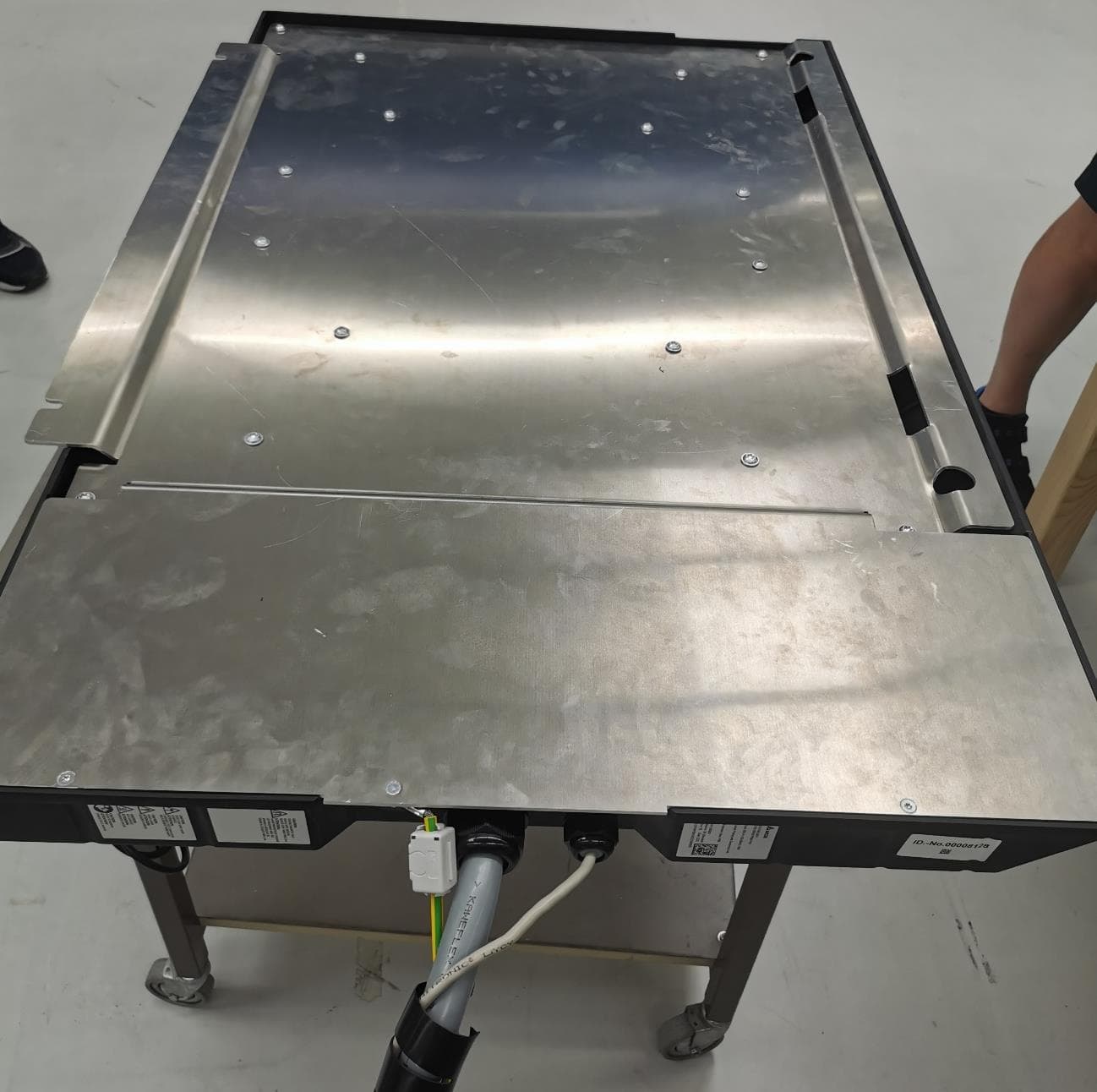
2AVWKWPU30KW
Sep 26, 2023Wireless Charger Primary Pad
Equipment Class
8CC - Part 18 Consumer Device