2AVZO-SN3200ASmart Node
75F, Inc.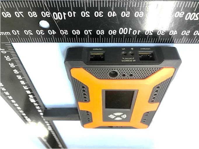
Click to zoom
Application Details
- Equipment Class
- DTS - Digital Transmission System
- Date of Grant
- Dec 21, 2020
- Application Purpose
- Original Equipment
- Date of Application
- Dec 21, 2020
- Equipment Note
- Smart Node
- Frequency Range
- 906.00000000 - 922.00000000
- Company
- 75F, Inc.
- Country
- United States
Documents & Files
Document Text
Text extracted from the exhibit documents filed with the FCC. Open a document above to read the original.
Users Manual
Support.75f.io | 888 612 7575 | APPLICATION A Remote Temperature and Humidity (RTH) sensor paired with a Smart Node results in a clean aesthetic in your space while minimizing installation times. The RTH provides highly accurate temperature and humidity values from your space and the Smart Node reports these values to the CCU. | PRECAUTIONS Take all precautions normally taken when installing a thermostat (e.g. not in direct sunlight, not on an exterior wall, not near heat producing equipment) Disconnect power before installing. Never connect or disconnect wiring with power applied Do NOT run RTH harness next to line voltage Install in accordance with all State and local codes. Fig.1 INSTALLATION INSTRUCTIONS REMOTE TEMPERATURE & HUMIDITY SMART NODE | RTH Support.75f.io | 888 612 7575 | FEATURES Accurate Temperature Accurate Humidity Wireless communication to Central Control Unit (CCU) | SPECIFICATIONS Remote Temperature Sensor Operating Environment: 0°F 122°F | MOUNTING Mounting the Smart Node. To Mount the 75F Smart Node, first identify the primary damper in the zone. If there is only one damper, that is the Wall 1"D Fig.2 Support.75f.io | 888 612 7575 primary damper. If there are two, pick the most accessible damper as you will need access to the Smart Node. Using the provided hex key bolts, screw the Smart Node to the damper side bracket cage nuts until snug. Installing the RTH. To install the RTH, you will need a 1 Determine where to ideally install the RTH. Also ensure the sensor will not be installed behind any objects such as picture frames, shelving units, equipment, etc. ground in the desired location. Drill the hole no lower highif at all possible. **For accurate performance ensure: There are no near heat producing devices That you are not on an exterior wall That the sensor will not be exposed to strong drafts or direct sunlight | WIRING Support.75f.io | 888 612 7575 Remote Temperature and Humidity Sensor (RTH) Harness. Both ends of the RTS harness are the same male connectors. Run one of the ends previously. Plug into the RTH. Plug the other end into the RTS port on the Smart Node. Powering the Smart Node. To power the smart node run your 18/2AWG bus line to the Power IN on the Smart Node. All devices with a shared transformer must be the same polarity. If you have another Smart Node that needs to be powered, daisy chain them from Power OUT to the next Power IN. Secure your cables so there is no excessive strain on any connections. Connect the Smart Damper(s). First connect the primary damper RJ45 lead to the Damper1 port on the Smart Node. Run the Cat5 extension cable from the Smart Node Damper2 port (Male end) to the RJ45 lead (Female end) on the secondary damper. Ensure all connections are tight Fig.3 Support.75f.io | 888 612 7575 and cables managed so no excess stress occurs on any connection. | PAIRING Pair the Smart Node to a zone that has been preconfigured or create and configure a zone yourself through Setup > Floor Plan on the CCU. Once power is supplied to the system and all Smart Nodes are displaying the default room. 1. Disconnect the tablet from the CM and carry it with. Pairing will be performed using Bluetooth. 2. On the RTH Smart Node into advertising mode. Alternatively, you can press the right button on the Smart Node until you reach advertising mode. 3. On the tablet choose the zone you wish t Pairing process will start. If no zones are displayed you will need to add all floors and rooms before pairing. 4. The tablet will request a PIN. Enter the PIN displayed on the Smart Node in the zone you are pairing. Fig.4 Support.75f.io | 888 612 7575 5. Pairing process will take a few more seconds and then complete . After a few more seconds the Smart Node will display the new zone name. The tablet will not display any zone data until it is reconnected to the CM where it will communicate over a 900Mhz channel. | TROUBLESHOOTING No display No power to controller. Check voltage to Smart Node is 24VAC. | 75F TECHNICAL SUPPORT If you need more information, please visit support.75f.io. Here installers will find instructional videos, installation guides, and more. You can also call 888.612.7575 for technical support. PROBLEM SOLUTION Fig.5 Fig.6 Support.75f.io | 888 612 7575 FCC Compliance Statement This device complies with part 15 of the FCC Rules. Operation is subject to the following two conditions: (1) this device may not cause harmful interference, and (2) this device must accept any interference received, including interference that may cause undesired operation. CAUTION: The grantee is not responsible for any changes or modifications not expressly approved by the party responsible for compliance. Such modifi authority to operate the equipment. NOTE: This equipment has been tested and found to comply with the limits for a Class B digital device, pursuant to part 15 of the FCC Rules. These limits are designed to provide reasonable protection against harmful interference in a residential installation. This equipment generates, uses, and can radiate radio frequency energy, and if not installed and used in accordance with the instructions, may cause harmful interference to radio communications. However, there is no guarantee that interference will not occur in a particular installation. If this equipment does cause harmful interference to radio or television reception, which can be determined by turning the equipment off and on, the user is encouraged to try to correct the interference by one or more of the following measures: Reorient or relocate the receiving antenna. Increase the separation between the equipment and receiver. Connect the equipment into an outlet on a circuit different from that to which the receiver is connected. Consult the dealer or an experienced radio/TV technician for help. This equipment complies with the FCC radiation exposure limits set forth for an uncontrolled environment. This equipment should be installed and operated with a minimum dis…
Text truncated - open the document above for the full version.
External Photos
Reference No.: WTX20X03012462W Page 2 of 14 Waltek Testing Group (Shenzhen) Co., Ltd. http://www.semtest.com.cn EXHIBIT 2 - EUT EXTERNAL PHOTOGRAPHS EUT View 1 EUT View 2 Reference No.: WTX20X03012462W Page 3 of 14 Waltek Testing Group (Shenzhen) Co., Ltd. http://www.semtest.com.cn EUT View 3 EUT View 4 Reference No.: WTX20X03012462W Page 4 of 14 Waltek Testing Group (Shenzhen) Co., Ltd. http://www.semtest.com.cn EUT View 5 EUT View 6
ID Label/Location Info
Reference No.: Waltek Testing Group (Shenzhen) Co., Ltd. http://www.semtest.com.cn EXHIBIT Proposed Specifications it is visible or easily accessible to the user, and shall not be readily detachable. The label shall be sufficiently durable to remain fully legible and intact on the device in all normal conditions of use throughout the device’s expected lifetime. Proposed Label Location on EUT FCC ID Location Reference No.: WTX20X03012462W Waltek Testing Group (Shenzhen) Co., Ltd. www.semtest.com.cn EXHIBIT 1 - PRODUCT LABELING Proposed FCC ID Label Format Specifications: The label shall be securely affixed to a permanently attached part of the device, in a location where it is visible or easily accessible to the user, and shall not be readily detachable. The label shall be sufficiently durable to remain fully legible and intact on the device in all normal conditions of use throughout the device’s expected lifetime. ed Label Location on EUT FCC ID Label Location WTX20X03012462W Waltek Testing Group (Shenzhen) Co., Ltd. www.semtest.com.cn PRODUCT LABELING Label Format The label shall be securely affixed to a permanently attached part of the device, in a location where it is visible or easily accessible to the user, and shall not be readily detachable. The label shall be sufficiently durable to remain fully legible and intact on the device in all normal conditions of use throughout the device’s ed Label Location on EUT WTX20X03012462W Waltek Testing Group (Shenzhen) Co., Ltd. PRODUCT LABELING Label Format The label shall be securely affixed to a permanently attached part of the device, in a location where it is visible or easily accessible to the user, and shall not be readily detachable. The label shall be sufficiently durable to remain fully legible and intact on the device in all normal conditions of use throughout the device’s ed Label Location on EUT Page 1 of 14 ANNEX PRODUCT LABELING The label shall be securely affixed to a permanently attached part of the device, in a location where it is visible or easily accessible to the user, and shall not be readily detachable. The label shall be sufficiently durable to remain fully legible and intact on the device in all normal conditions of use throughout the device’s 14 The label shall be securely affixed to a permanently attached part of the device, in a location where it is visible or easily accessible to the user, and shall not be readily detachable. The label shall be sufficiently durable to remain fully legible and intact on the device in all normal conditions of use throughout the device’s The label shall be securely affixed to a permanently attached part of the device, in a location where it is visible or easily accessible to the user, and shall not be readily detachable. The label shall be sufficiently durable to remain fully legible and intact on the device in all normal conditions of use throughout the device’s The label shall be securely affixed to a permanently attached part of the device, in a location where it is visible or easily accessible to the user, and shall not be readily detachable. The label shall be sufficiently durable to remain fully legible and intact on the device in all normal conditions of use throughout the device’s The label shall be securely affixed to a permanently attached part of the device, in a location where it is visible or easily accessible to the user, and shall not be readily detachable. The label shall be sufficiently durable to remain fully legible and intact on the device in all normal conditions of use throughout the device’s The label shall be securely affixed to a permanently attached part of the device, in a location where it is visible or easily accessible to the user, and shall not be readily detachable. The label shall be sufficiently durable to remain fully legible and intact on the device in all normal conditions of use throughout the device’s
Internal Photos
Reference No.: WTX20X03012462W Page 5 of 14 Waltek Testing Group (Shenzhen) Co., Ltd. http://www.semtest.com.cn EXHIBIT 3 - EUT INTERNAL PHOTOGRAPHS EUT Housing and Board View Solder Board-Component View 1 Reference No.: WTX20X03012462W Page 6 of 14 Waltek Testing Group (Shenzhen) Co., Ltd. http://www.semtest.com.cn Solder Board-Component View 2 Reference No.: WTX20X03012462W Page 7 of 14 Waltek Testing Group (Shenzhen) Co., Ltd. http://www.semtest.com.cn Solder Board-Component View 3 Solder Board-Component View 4
Internal Photos
Reference No.: WTX20X03012462W Page 8 of 14 Waltek Testing Group (Shenzhen) Co., Ltd. http://www.semtest.com.cn Solder Board-Component View 5 Solder Board-Component View 6 Reference No.: WTX20X03012462W Page 9 of 14 Waltek Testing Group (Shenzhen) Co., Ltd. http://www.semtest.com.cn Solder Board-Component View 7 Solder Board-Component View 8 Reference No.: WTX20X03012462W Page 10 of 14 Waltek Testing Group (Shenzhen) Co., Ltd. http://www.semtest.com.cn Solder Board-Component View 9 Solder Board-Component View 10 Reference No.: WTX20X03012462W Page 11 of 14 Waltek Testing Group (Shenzhen) Co., Ltd. http://www.semtest.com.cn Antenna View
RF Exposure Info
RF Exposure Requirements Product Description: Smart Node Model No.: 75F-SN3200 FCC ID: 2AVZO-SN3200A According to the KDB 447498 D01 v06 section 4.3.1, for 100 MHz to 6 GHz and test separation distances ≤ 50 mm, the 1-g and 10-g SAR test exclusion thresholds are determined by the following: [(max. power of channel, including tune-up tolerance, mW)/(min. test separation distance, mm)] · [√f(GHz)] ≤ 3.0 for 1-g SAR and ≤ 7.5 for 10-g extremity SAR, where - f(GHz) is the RF channel transmit frequency in GHz - Power and distance are rounded to the nearest mW and mm before calculation - The result is rounded to one decimal place for comparison Calculation Result: For SRD Tx frequency range: 906MHz-922MHz Min. test separation distance: 5mm Maximum Conducted Output Power: 4.672dBm Tune-Up output power: 5dBm RF channel transmit frequency: 914MHz Result: 0.6 Limit: 3.0 The exclusion thresholds is 0.6 < 3 For BLE Tx frequency range: 2402MHz-2480MHz Min. test separation distance: 5mm Maximum Conducted Output Power: 3.57dBm Tune-Up output power: 4.0dBm RF channel transmit frequency: 2480MHz Result: 0.8 Limit: 3.0 The exclusion thresholds is 0.8 < 3 So the transmitter complies with the RF exposure requirements and the SAR is not required.
Test Report
Waltek Testing Group (Shenzhen) Co., Ltd. http://www.semtest.com.cn Page 1 of 39 TEST REPORT Reference No. .................. : WTX20X03012462W FCC ID.............................. : 2AVZO-SN3200A Applicant.......................... : 75F, Inc. Address ........................... : 1650 W 82nd St, Suite 200, Bloomington, MN 55431 Product Name .................. : Smart Node Test Model........................ : 75F-SN3200 Standards ........................ : FCC Part 15.247 Date of Receipt sample .... : Sept.01, 2020 Date of Test ...................... : Sept.01, 2020 to Oct.26, 2020 Date of Issue .................... : Oct.26, 2020 Test Result ....................... : Pass Remarks: The results shown in this test report refer only to the sample(s) tested, this test report cannot be reproduced, except in full, without prior written permission of the company. The report would be invalid without specific stamp of test institute and the signatures of compiler and approver. Prepared By: Waltek Testing Group (Shenzhen) Co., Ltd. Address: 1/F., Room 101, Building 1, Hongwei Industrial Park, Liuxian 2nd Road, Block 70 Bao'an District, Shenzhen, Guangdong, China Tel.: +86-755-33663308 Fax.: +86-755-33663309 Tested by: Reviewed By: Approved & Authorized By: Jason Su / Project Engineer Lion Cai / RF Manager Silin Chen / Manager Reference No.: WTX20X03012462W Page 2 of 39 Waltek Testing Group (Shenzhen) Co., Ltd. http://www.semtest.com.cn TABLE OF CONTENTS 1. GENERAL INFORMATION ................................................................................................................................... 4 1.1 PRODUC T DESCRIPTION FOR EQUIPMEN T UNDER TEST (EUT) ............................................................................... 4 1.2 TEST STANDARDS ................................................................................................................................................... 5 1.3 TEST METHODOLOGY ............................................................................................................................................. 5 1.4 TEST FACILITY ........................................................................................................................................................ 5 1.5 EUT SETUP AND TEST MODE ................................................................................................................................. 6 1.6 MEASUREMENT UNC ERTAINTY............................................................................................................................... 6 1.7 TEST EQUIPMEN T LIST AND DETAILS ..................................................................................................................... 7 2. SUMMARY OF TEST RESULTS............................................................................................................................ 9 3. RF EXPOSURE ........................................................................................................................................................ 10 3.1 STAN DARD APPLICABLE ....................................................................................................................................... 10 3.2 TEST RESULT ........................................................................................................................................................ 10 4. ANTENNA REQUIREMENT................................................................................................................................. 11 4.1 STAN DARD APPLICABLE ....................................................................................................................................... 11 4.2 EVALUATION INFORMATION ................................................................................................................................. 11 5. POWER SPECTRAL DENSITY ............................................................................................................................ 12 5.1 STAN DARD APPLICABLE ....................................................................................................................................... 12 5.2 TEST SETUP BLOCK DIAGRAM .............................................................................................................................. 12 5.3 TEST PROCEDURE ................................................................................................................................................. 12 5.4 SUMMARY OF TEST RESULTS/PLO TS .................................................................................................................... 12 6. DTS BANDWIDTH.................................................................................................................................................. 14 6.1 STAN DARD APPLICABLE ....................................................................................................................................... 14 6.2 TEST SETUP BLOCK DIAGRAM .............................................................................................................................. 14 6.3 TEST PROCEDURE ................................................................................................................................................. 14 6.4 SUMMARY OF TEST RESULTS/PLO TS .................................................................................................................... 14 7. RF OUTPUT POWER ............................................................................................................................................. 16 7.1 STAN DARD APPLICABLE ....................................................................................................................................... 16 7.2 TEST SETUP BLOCK DIAGRAM .............................................................................................................................. 16 7.3 TEST PROCED…
Text truncated - open the document above for the full version.
Test Setup Photos
Reference No.: WTX20X03012462W Page 12 of 14 Waltek Testing Group (Shenzhen) Co., Ltd. http://www.semtest.com.cn EXHIBIT 4 - TEST SETUP PHOTOGRAPHS Conducted Emission Test Setup Radiation Emission Test Setup (Below 30MHz) Reference No.: WTX20X03012462W Page 13 of 14 Waltek Testing Group (Shenzhen) Co., Ltd. http://www.semtest.com.cn Radiation Emission Test Setup (30MHz to 1GHz) Radiation Emission Test Setup (1GHz to 18GHz) Reference No.: WTX20X03012462W Page 14 of 14 Waltek Testing Group (Shenzhen) Co., Ltd. http://www.semtest.com.cn Radiation Emission Test Setup (Above 18GHz) ***** END OF REPORT *****
Contact Information
Applicant
Alex Schwalbe(Quality Assurance Technician)
Test Firm
Waltek Testing Group (Shenzhen) Co., Ltd.Jandy So
Technical Specifications
| # | Rule Parts | Frequency Range | Power Output |
|---|---|---|---|
| 1 | 15C | 906 MHz - 922 MHz | 2.90 mW |
Other Applications from 75F, Inc.
2AVZO-101566
Apr 10, 2026WIRED MULTI SENSOR
Equipment Class
DTS - Digital Transmission System2AVZO-101317
Apr 03, 2026Wireless MultiSensor
Equipment Class
DTS - Digital Transmission System2AVZO-101565
Mar 27, 2026MYSENSE
Equipment Class
DTS - Digital Transmission System2AVZO-101644
Dec 14, 2025MyStat
Equipment Class
DTS - Digital Transmission System
2AVZO-T8045PC
Dec 02, 2023TABLET PC
Equipment Class
DSS - Part 15 Spread Spectrum Transmitter