2AW5W-V1PDash Camera
REXING INC.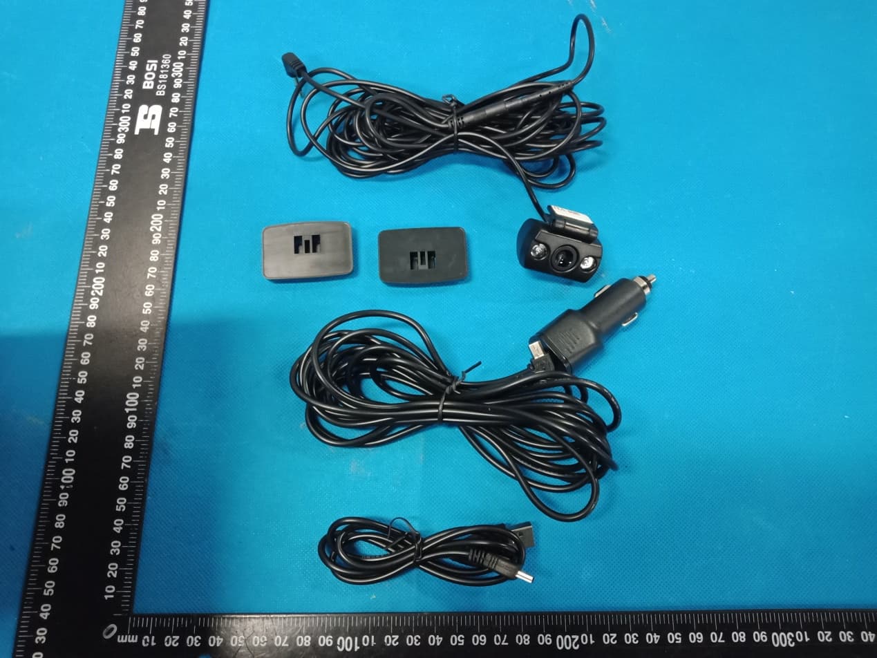
Click to zoom
Application Details
- Equipment Class
- DTS - Digital Transmission System
- Date of Grant
- Aug 03, 2020
- Application Purpose
- Original Equipment
- Date of Application
- Aug 02, 2020
- Equipment Note
- Dash Camera
- Frequency Range
- 2412.00000000 - 2462.00000000
- Company
- REXING INC.
- Country
- United States
Documents & Files
Document Text
Text extracted from the exhibit documents filed with the FCC. Open a document above to read the original.
Users Manual
V1P Quick Start Guide Guide de démarrage rapide de la V1P Guida di avvio rapido V1P V1P Schnellstartanleitung Guía de inicio rápido V1P V1P クイックスタートガイド FR IT DE SP JP 2 Table of Contents English Overview What’s in the Box Camera Overview Installation Basic Operation 日本語 概説 箱の中には何が入っていますか カメラの概説 画面のアイコン 基本操作 Français Aperçu Que contient la Boîte Aperçu de la Caméra Installation Opération de Base Italiano Descrizione Nella Confezione Descrizione Telecamera Installazione Funzionamento Base page 4 5 6 8 13 20 21 22 24 29 36 37 38 40 45 52 53 54 56 61 3 Español Visión General Qué hay en la Caja Resumen de la Cámara Instalación Operación Básica Deutsch Übersicht Verpackungsinhalt Kamera übersicht Installation Grundbedienung 68 69 70 72 77 84 85 86 88 93 page 4 1. Overview Thank you for choosing REXING! We hope you love your new product as much as we do. If you need assistance, or have any suggestions to improve it, please contact us. You can reach us via [email protected] or call us at (203) 800-4466. Our support team will respond you as soon as possible. Always a surprise in Rexing. Check us out here. https://www.facebook.com/rexingusa/ https://www.instagram.com/rexingdashcam/ https://www.rexingusa.com/support/registration/ FacebookInstagramSite 5 1. Overview 1. Rexing V1P Dash Cam 2. Car Charger 3. Rear Camera 4. Dash Cam Mount Plate & 3M Adhesive 5. Mini-USB Cable 6. Cable Management Tool 7. Cable Clips© 8. V1P Quick Start Guide 9. V1P Safety Guide 1. 6. 7.8.9. 2.3.4. 2. What’s in the box 5. V1P Quick Start Guide Guide de démarrage rapide de la V1P Guida di avvio rapido V1P V1P Schnellstartanleitung Guía de inicio rápido V1P V1P クイックスタートガイド FR IT DE SP JP 6 3. Camera Overview 1. Micro SD Card Slot 2. Power Button 3. Reset Button 4. Menu Button 5. Mode Button 6. REC (Record) Button * 7. OK (Confirm) Button ** 8. MIC (Microphone) Button *** 9. Screen Button 10. Mini-USB Port 11. GPS Logger Port 12. Rear Camera Port (Not Support) 13. Lens Angle Adjustment * The Camera is recording when the LED is flashing red. ** The Camera is recording when the LED is flashing red. The device charging or powered on when the LED is solid blue. *** The device is charging or powered on when the LED is solid blue. 1. 10. 11. 5.6.8. 7. 9. 2. 3. 4. 12. 13. 7 Screen Icons GPS Signal (not connected) GPS Signal (locked) Recording Time (Current Clip) Video Resolution Parking Mode (On) G-Sensor Sensitivity Level Memory Card (Inserted) Battery Charging WDR Mode (On) Recording (On) Recording Standby Status Loop Recording Time Exposure Value MIC (Off) MIC (On) Current Date (DD/MM/YYY) Time (24H) Plate Number 8 4. Installation Step 1: Install the Dash Cam Place the 3M tape on the Mount and properly orient the Mount square to the roof and hood line of the vehicle. Important! Ensure the T-interlock on the Mount is oriented in the correct direction. Firmly press the Mount onto the windshield. Wait at least 20 minutes before mounting the camera. Orientation mount as shown Step 2: Insert the Memory Card The Rexing V1P accepts [Class 10/ UHS-1 or higher] Micro SD memory cards up to 256GB. You will need to insert a memory card before you can begin recording. Before inserting or removing a memory card, first ensure you’ve powered down the device. Gently push the memory card in until you hear a click, and allow the spring release to push the card out. 9 Step 3: Power the Camera and Format the Memory Card Power the camera by connecting the charger to the car cigarette lighter and camera. To ensure the V1P records to your memory card properly and without error. Before you start using a new memory card, you must format the card within the camera using the format function. Always backup important data stored on the memory card before formatting. To format the memory card, make sure you have inserted your memory card, then turn on the device by connecting to a power source. Press REC to stop recording. Then press the MENU button twice to enter the System Setup Menu. Use the REC and MIC buttons and go to the Format setting. Press the OK Button to confirm the selection. Press the Power button to turn the power off 10 Press the Menu button twice Press the OK button to confirm formatting the card Connect Mini- USB to the camera Blue LED lights indicate the device is charging or powered You may now disconnect from power. The camera will shut down after 3 seconds. The camera should begin recording automatically the next time it is powered on. 11 Step 4: Mount the Rear Camera Mount the rear camera as shown below. Use the provided rear camera cable to connect the rear camera to the front camera. Plug Rear Camera into the Dash Cam Rear Camera installation 12 Step 5: Installing the Camera onto the Windshield Place the camera on the mount and carefully route the power cable around the windscreen and tuck in under the trim. Plug the Car Charger Cable into a 12V DC power outlet or the car cigarette lighter. Connect car charger to the camera. The camera will auto-start recording once powered on. Plug Mini 5 pin Connector to the Dash Cam Route power cable to the Dash Cam Plug charger into power outlet or cigarette lighter 13 5. Basic Operation Device Power The device is automatically powered on when plugged into a 12V accessory socket or cigarette lighter and receives a charge (i.e.: the vehicle is started.) To turn the device on manually, press and hold the POWER button until the welcome screen appears. The camera will automatically start recording when powered on. Press an hold the POWER button to turn the device on manually 14 Menu Settings Power the camera on. If the camera is recording, press the REC button to stop recording. Press the MODE button and toggle to the desired mode. Press the MENU button once to enter the settings menu for a Mode. Press the MENU button twice to enter the System Settings. System icon Video Mode icon Press the Menu button to select the desired setting Press the Mode button and toggle to the desired Mode 15 Video Record…
Text truncated - open the document above for the full version.
Cover Letter(s)
Co m Ad d Pr o Mo d V3 B Pr o We act We an d issu our Sig Na m Title Com mpany: RE dress: 264 oduct Name del Numbe Basic oduct Desc authorize M on our beha declare tha d certificatio ues concern behalf shal nature: me: e: mpany: EXING INC. Quarry R d e: Dash Ca er(s): V1P, V ription: Da MiCOM Lab alf on all ma at MiCOM L n of equipm ning the app ll have the s Yuhe Sun General M REXING I Agen d., Unit D M mera V1-4K, V1P ash Camera bs Inc., 575 atters conce Labs Inc. is ment to the r proval applic same effect Manager NC. REXING nt Auth Milford, CT 0 P-3, V1P Pr a Boulder C o erning the c allowed to f regulatory a cation. Any t as acts of G INC. horizat 06460, USA ro, V1 Max, ourt, Pleasa certification forward all i agencies as and all acts our own. tion A V1P Max, anton, Califo of above na information s required a s carried ou Date: V3, ornia 94566 amed equip related to t nd to discu ut by MiCOM Aug. 03, 20 6, USA, to pment. the approva ss any M Labs on 020 al
Cover Letter(s)
Office o Federa 7435 O Columb USA Subjec t FCC ID To Wh o Pursua are req u docume These d propriet might b It is ou r corresp docume authoriz Sincer e Signat u Name: Y Title: G of Engineeri l Communic Oakland Mills bia, MD 210 t; Request f D: 2AW5W- om It May C nt to the pro uesting the ents from pu documents tary informa be harmful to Schema Block D Parts Lis Operatio r understand pondence du ents and thi zation is iss ely, ure: Yuhe Sun eneral Ma n ing Techno cations Com s Road 046 for Confiden -V1P Concern, ovisions of t Commissio ublic disclos contain det ation in ope o our comp atic Diagram iagram st onal Descri ding that all uring the ce s informatio sued. nager logy mmission ntiality the Commis on to withho sure indefin tailed syste ration of th e any and wo m ption l measurem ertification re on will be av REXING IN ssion’s rule old the follow nitely. m and equi e equipmen ould give co ment test rep eview proce vailable for NC. s Title 47 S wing attach pment desc nt. The publ ompetitors a ports, FCC ess cannot public revi e Sections §0. hment(s) as criptions an ic disclosu r an unfair ad ID label for be granted ew once the Date: Aug. 457 and § 0 confidentia d are consi re of these d vantage in mat and as confide n e grant of eq 03, 2020 0.459, we al dered as documents the market . ntial quipment .
Cover Letter(s)
Model Difference Declaration To Whom It May Concern, We, REXING INC.(Dash Camera) Trademark:REXING; Model Number: V1P, V1-4K, V1P-3, V1P Pro, V1 Max, V1P Max, V3, V3 Basic; All model’s the function, software and electric circuit are the same, only with a product model named different for commercial purpose. Test sample model: V1P. Please contact me if you have any question. Name: Yuhe Sun Date: Aug. 03, 2020 Title: General Manager Signature of applicant:
External Photos
Annex A External Photos Report No.: HK2007141967‐E Page 1 of 4 Report No.: HK2007141967‐E Page 2 of 4 Report No.: HK2007141967‐E Page 3 of 4 Report No.: HK2007141967‐E Page 4 of 4
ID Label/Location Info
FCC ID LABEL: Label Location Width: 2cm Long: 4cm FCC ID: 2AW5W-V1P Product name: Dash Camera Model No.: V1P
Internal Photos
Annex B Internal Photo Report No.:HK2007141967-E Page 1 of 5 Antenna Report No.:HK2007141967-E Page 2 of 5 Report No.:HK2007141967-E Page 3 of 5 Report No.:HK2007141967-E Page 4 of 5 Report No.:HK2007141967-E Page 5 of 5
RF Exposure Info
MPE ESTIMATION FCC ID: 2AW5W-V1P 1,Limit for General Population/ Uncontrolled Exposures Frequency Power density (mW/ cm 2 ) Averaging time(minutes) 300MHz----1.5GHz F/1500 30 1.5GHz---100GHz 1.0 30 Note: F= Frequency in MHz 2, Estimation Result WIFI Mode Max PK Output power(dBm) Tune Up Power(dBm) Max Tune Up power(mW) Antenna Gain(dBi) Antenna Gain (numerical) MPE ( mW/cm²) 2.4G WIFI 14.49 14±1(15) 31.623 1 1.2589 0.00792 Note: Note: The estimation distance is 20cm Note: PK Output power= conducted power. Conducted power see the test report HK2007141967-E, antenna gain=1dBi when the minimum test separation distance is >20 cm, a distance of 20 cm is applied to determine RF Exposure test exclusion. The test exclusion threshold is 0.00792 mW/cm² which is< 1.0mW/cm², RF Exposure testing is not required. -------The End-------
Test Report
Report No.: HK2007141967-E FCC TEST REPORT Test report On Behalf of REXING INC. For Dash Camera Model No.: V1P, V1-4K, V1P-3, V1P Pro, V1 Max, V1P Max, V3, V3 Basic FCC ID: 2AW5W-V1P Prepared for : REXING INC. 264 Quarry Rd., Unit D Milford, CT 06460, USA Prepared By : Shenzhen HUAK Testing Technology Co., Ltd. 1F, B2 Building, JunfengZhongchengZhizao Innovation Park, Fuhai Street, Bao'an District, Shenzhen City, China Date of Test: Jul. 22, 2020 ~Jul. 29, 2020 Date of Report: Jul. 29, 2020 Report Number: HK2007141967-E Report No.: HK2007141967-E Page 2 of 69 TEST RESULT CERTIFICATION Applicant’s name .................. : REXING INC. Address .................................. : 264 Quarry Rd., Unit D Milford, CT 06460, USA Manufacture's Name ............. : KA FUNG Technology Co., Ltd. Address .................................. : RM202, C5 Building HengFeng Industry City., 739# ZhouShi Rd., Bao’an Shenzhen China Product description Trade Mark: REXING Product name ............................ : Dash Camera Model and/or type reference . : V1P, V1-4K, V1P-3, V1P Pro, V1 Max, V1P Max, V3, V3 Basic Standards .............................. : FCC Rules and Regulations Part 15 Subpart C Section 15.247 ANSI C63.10: 2013 This publication may be reproduced in whole or in part for non-commercial purposes as long as the Shenzhen HUAK Testing Technology Co., Ltd. is acknowledged as copyright owner and source of the material. Shenzhen HUAK Testing Technology Co., Ltd. takes no responsibility for and will not assume liability for damages resulting from the reader's interpretation of the reproduced material due to its placement and context. Date of Test ............................................ : Date (s) of performance of tests ............. : Jul. 22, 2020 ~Jul. 29, 2020 Date of Issue ........................................... : Jul. 29, 2020 Test Result ............................................... : Pass Testing Engineer : (Gary Qian) Technical Manager : (Eden Hu) Authorized Signatory : (Jason Zhou) Report No.: HK2007141967-E Page 3 of 69 TABLE OF CONTENTS 1. Test Result Summary ............................................................................... 5 1.1. TEST PROCEDURES AND RESULTS ............................................................................................... 5 1.2. TEST FACILITY .................................................................................................................................. 5 1.3. MEASUREMENT UNCERTAINTY ............................................................................................................... 6 2. EUT Description ........................................................................................ 7 2.1. GENERAL DESCRIPTION OF EUT ................................................................................................... 7 2.2. CARRIER FREQUENCY OF CHANNELS ..................................................................................................... 8 2.3. OPERATION OF EUT DURING TESTING .................................................................................................... 8 2.4. DESCRIPTION OF TEST SETUP ....................................................................................................... 9 3. Genera Information ................................................................................. 10 3.1. TEST ENVIRONMENT AND MODE ............................................................................................................ 10 3.2. DESCRIPTION OF SUPPORT UNITS ........................................................................................................ 11 4. Test Results and Measurement Data .................................................... 12 4.1. CONDUCTED EMISSION ........................................................................................................................ 12 4.2. TEST RESULT ...................................................................................................................................... 14 4.3. MAXIMUM CONDUCTED OUTPUT POWER .............................................................................................. 16 4.4. EMISSION BANDWIDTH ......................................................................................................................... 18 4.5. POWER SPECTRAL DENSITY ................................................................................................................ 24 4.6. CONDUCTED BAND EDGE AND SPURIOUS EMISSION MEASUREMENT ..................................................... 30 4.7. RADIATED SPURIOUS EMISSION MEASUREMENT ................................................................................... 40 4.8. ANTENNA REQUIREMENT ............................................................................................................. 66 4.9. PHOTOGRAPH OF TEST ................................................................................................................. 67 4.10. PHOTOS OF THE EUT ..................................................................................................................... 69 Report No.: HK2007141967-E Page 4 of 69 ** Modifited History ** Revison Description Issued Data Remark Revsion 1.0 Initial Test Report Release Jul. 29, 2020 Jason Zhou Report No.: HK2007141967-E Page 5 of 69 1. Test Result Summary 1.1. TEST PROCEDURES AND RESULTS Requirement CFR 47 Section Result Antenna requirement §15.203/§15.247 (c) PASS AC Power Line Conducted Emission §15.207 PASS Conducted Peak Output Power §15.247 (b)(3) PASS 6dB Emission Bandwidth §15.247 (a)(2) PASS Power Spectral Density §15.247 (e) PASS Band Edge 1§5.247(d) PASS Spurious Emission §15.205/§15.209 PASS Note: 1. PASS: Test item meets the requirement. 2. Fail: Test item does not meet the requirement. 3. N/A: Test case does not apply to the test object. 4. The test result judgment is decided by the limit of test standard. 1.2. TEST FACILITY Test Firm : …
Text truncated - open the document above for the full version.
Test Setup Photos
Conducted Emission Radiated Emissions
Contact Information
Applicant
Yuhe Sun(General Manager)
Technical Contact
Test Firm
Shenzhen HUAK Testing Technology Co., Ltd.Jason Zhou
[email protected]+86-755-23029901
Technical Specifications
| # | Rule Parts | Frequency Range | Power Output |
|---|---|---|---|
| 1 | 15C | 2.41 GHz - 2.46 GHz | 28.12 mW |
Other Applications from REXING INC.
2AW5W-R4MD
Apr 24, 2026Dash Camera
Equipment Class
NII - Unlicensed National Information Infrastructure TX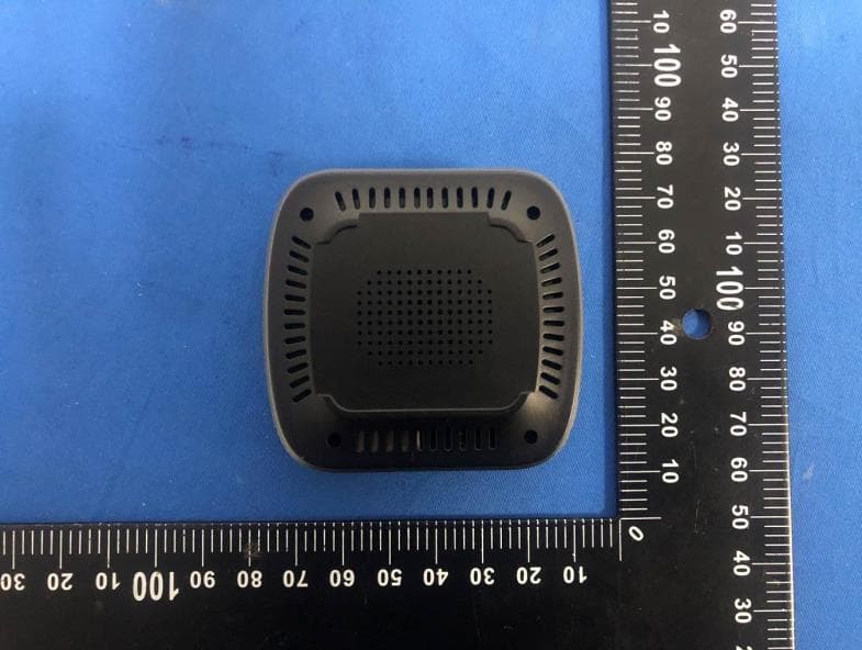
2AW5W-AIBOX
Apr 14, 2026CARPLAY
Equipment Class
NII - Unlicensed National Information Infrastructure TX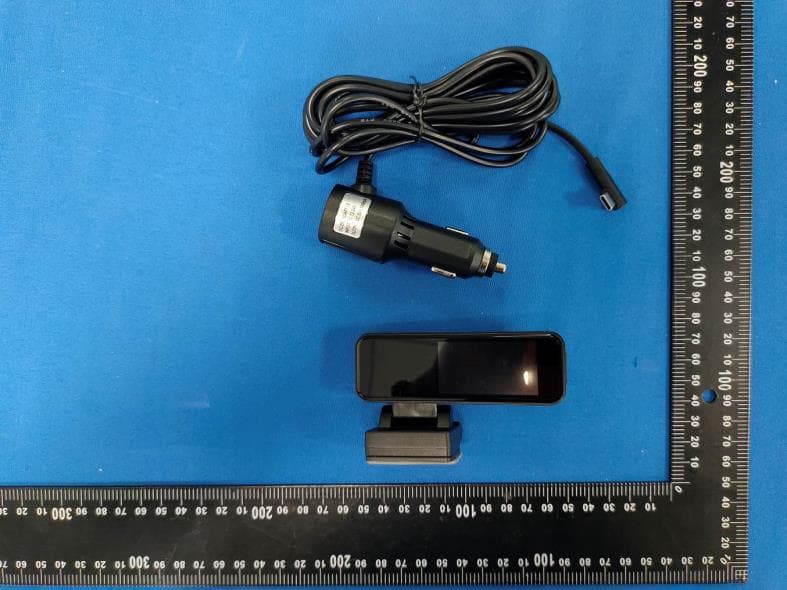
2AW5W-C1B
Apr 13, 2026Dash Camera
Equipment Class
DTS - Digital Transmission System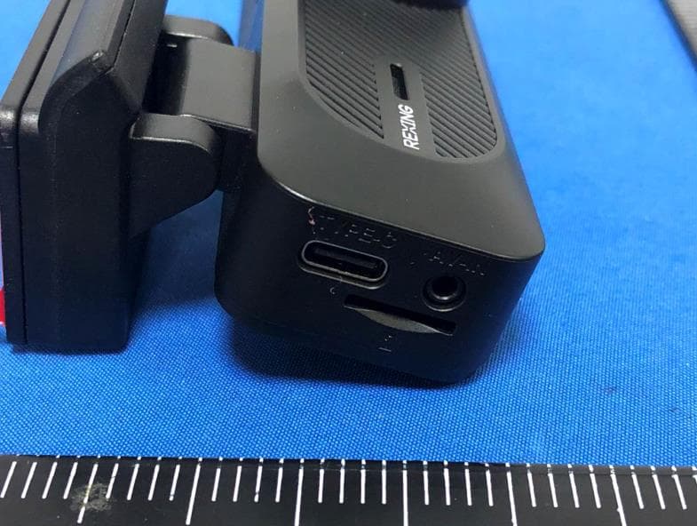
2AW5W-C2B
Apr 13, 2026Dash Camera
Equipment Class
DTS - Digital Transmission System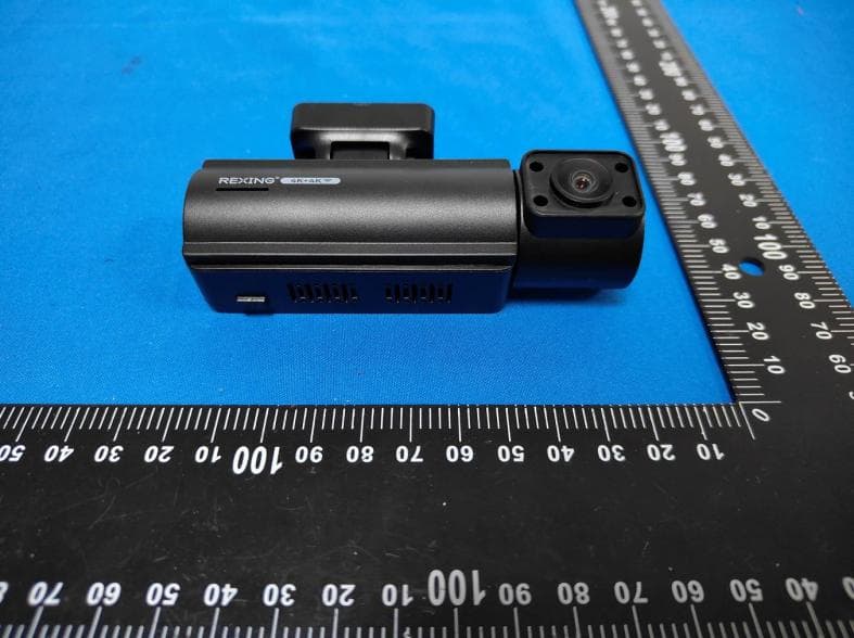
2AW5W-C2PRO
Feb 03, 2026Dash Cam
Equipment Class
NII - Unlicensed National Information Infrastructure TX