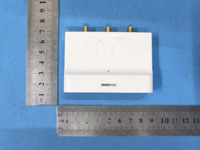
2AW6Y-CAM11Trax Shelf Camera v1.1
Trax Technology Solutions Pte Ltd
Click to zoom
Application Details
- Equipment Class
- DTS - Digital Transmission System
- Date of Grant
- Jul 12, 2021
- Application Purpose
- Original Equipment
- Date of Application
- Jul 12, 2021
- Equipment Note
- Trax Shelf Camera v1.1
- Frequency Range
- 2412.00000000 - 2462.00000000
- Country
- Singapore
Documents & Files
Document Text
Text extracted from the exhibit documents filed with the FCC. Open a document above to read the original.
Users Manual
Trax Shelf Camera V1.1 Device Model: 2018-01 Operating manual Contents Specifications ..................................................................................................................................................... 3 System overview ............................................................................................................................................... 4 Required tools ............................................................................................................................................... 5 Perquisites ..................................................................................................................................................... 5 Installation steps ........................................................................................................................................... 6 Replacing batteries ............................................................................................................................................ 8 Troubleshooting ................................................................................................................................................ 9 Camera does not connect to the network ................................................................................................... 9 Camera head is loose .................................................................................................................................... 9 Camera does not turn on .............................................................................................................................. 9 Battery operated ....................................................................................................................................... 9 Power cable operated ............................................................................................................................... 9 Camera does not send images ...................................................................................................................... 9 Support ........................................................................................................................................................... 10 Warnings ......................................................................................................................................................... 11 FCC Compliance Statement ........................................................................................................................... 12 FCC Radiation Exposure Statement ............................................................................................................... 13 Specifications Power supply • 4x AA batteries Or • 5V/500mA via power cord Wi-Fi • 802.11 b/g/n Radio • Supports WPA2 personal and enterprise security Camera module • Resolution- 2592X1944 QSXGA, 5MP • Aspect ratio- 4:3 • f. number- 2.8 • DFOV- 67.4 • CDAF autofocus Operating conditions • For indoor use only • -20 to 50C operating condition and -40 to 70C storage • 90% humidity System overview Trax Shelf Camera V1.1 is a low energy, low profile wireless camera for the retail industry. Trax Shelf Camera V1.1 is designed to capture and digitize the shelf; It consists of a camera body and an adjustable lens. Trax Shelf Camera V1.1 can be powered using a power cable OR on 4x AA batteries. The control and I/O of the camera is visible on its side and includes: • Datalink port • Power cable input for non-battery power operation • ON/OFF switch Required tools • Trax Shelf Camera V1.1 • Philips screwdriver sizes 1.0 mm • Hex screwdriver size 2.0mm -Lens adjustment • Hex screwdriver 2.5mm - bracket holder Perquisites Prior to starting the installation, make sure to verify the following things: 1. Wi-Fi router, access point or any other Wi-Fi infrastructure 2. Gateway device is on and connected both to the local network and the cloud. 3. Trax Shelf Camera V1.1 is pre-configured to the installation site Installation steps 1. Locate the designated installation spot according to the installation plan. 2. Verify the camera body and lens position on the shelf – use the pully to extend the camera lens to its proper position. 3. Prepare the installation surface by cleaning any dust or glue residue from the shelf. 4. Remove the adhesive cover from the two double-sided tape strips on the camera body 5. Mount the camera body in the designated area, press the camera body firmly to the surface to make sure both strips are touching the mounting surface. 6. Remove the adhesive cover from the double-sided tape strip of the camera lens and place it in the designated area 7. Turn on the camera by using the power button – a blue LED indicator should turn on for several seconds. 8. Verify the lens position by inspecting the image received in the gateway unit. 9. Adjust the camera lens so the frame would include the subject - to rotate the lens on its pivot, use the hex screwdriver to loosen (anti-clockwise) or tighten (clockwise) the lens pivot. 10. Pull the pully back gently, until no slack is noticeable without applying force on the ribbon cable. Replacing batteries When operating on batteries, the camera may required battery replacement from time to time. 1. Turn off the camera using the ON/OFF switch 2. Unscrew the screw at the bottom end of the battery panel 3. Open the panel, replace the 4x AA batteries with new ones. 4. Close the panel and refasten the screw. Support Camera does not connect to the network Camera attempts to resend image 3 times – blue LED turn on and off 3 consecutive times 1. Verify Wi-Fi network is available 2. Verify gateway unit is connected and configured on the network 3. Try using the same device closer to the Wi-Fi access point In case the steps above do not resolve the issue, reach support for assistance- refer to support section Camera head is loose 1. Using a 2.0mm size hex key, turn th…
Text truncated - open the document above for the full version.
Cover Letter(s)
DATE : 2021-03-05 Federal Communications Commission Authorization & Evaluation Division 7345 Oakland Mills Road Columbia, Maryland 21046 Authority to Act as Agent On our behalf, I appoint Jason Wu of Global United Technology Services Co., Ltd.and No. 123-128, Tower A, Jinyuan Business Building, No.2, Laodong Industrial Zone, Xixiang Road, Baoan District, Shenzhen, Guangdong, China to act as our agent in the preparation of this application for equipment certification. I certify that submitted documents properly describe the device or system for which equipment certification is sought. I also certify that each unit manufactured, imported or marketed, as defined in the Federal Communications Commission’s regulations will have affixed to it a label identical to that submitted for approval with this application. For instances where our authorized agent signs the application for certification on our behalf, I acknowledge that all responsibility for complying with the terms and conditions for certification, still resides with Trax Technology Solutions Pte Ltd and 65 Chulia Street, #19-01, OCBC Centre, Downtown Core 049513, Singapore Signature: Name: Sakal Heng Title: Legal Counsel Company: Trax Technology Solutions Pte Ltd
Cover Letter(s)
DATE : 2021-03-05 Equipment Autorisation Division Federal Communications Commission 7435 Oakland Mills Road Columbia, MD 21046 FCC ID: 2AW6Y-CAM11 Product Name: Trax Shelf Camera v1.1 Request for Confidentiality To Whom It May Concern, Pursuant to the provisions of the Commission’s rules Title 47 Sections §0.457 and §0.459, we are requesting the Commission to withhold the following attachment(s) as confidential documents from public disclosure indefinitely. These documents contain detailed system and equipment descriptions and are considered as proprietary information in operation of the equipment. The public disclosure of these documents might be harmful to our company and would give competitors an unfair advantage in the market. Schematic Diagram Block Diagram Operational Description In additional to above mentioned documents, in order to comply with the marketing regulations in Title 47 CFR §2.803 and the importation rules in Title 47 CFR §2.1204, while ensuring that business sensitive information remains confidential until the actual marketing of newly authorized devices, we request Short Term Confidentiality of the following attachment(s); External Photos Test Setup Photos Internal Photos User Manual For 45 days, pursuant to Public Notice DA 04-1705. OR For 180 days pursuantto KDB 726920 D01. It is our understanding that all measurement test reports, FCC ID label format and correspondence during the certification review process cannot be granted as confidential documents and this information will be available for public review once the grant of equipment authorization is issued. Signature: Name: Sakal Heng Title: Legal Counsel Company: Trax Technology Solutions Pte Ltd
ID Label/Location Info
Manufacturer Trax Technology Solutions Pte Ltd Label Declaration sticker *Serial Number is also available on the declaration sticker Serial sticker Label size 25mm (w) x 92mm (h) - Declaration sticker (5.3 in label location) 40mm (w) x 5mm (h) - QR S/N sticker (5.2 in label location) Label location
RF Exposure Info
FCC ID: 2AW6Y-CAM11 IC: 26479-CAM11 RF Exposure Evaluation FCC Limits The criteria listed in the following table shall be used to evaluate the environment impact of human exposure to radio frequency (RF) radiation as specified in 1.1307(b) Limits for Maximum Permissible Exposure (MPE) Frequency range (MHz) Electric field strength (V/m) Magnetic field strength (A/m) Power density (mW/cm 2 ) Averaging time (minutes) (A) Limits for Occupational/Controlled Exposures 0.3–3.0 614 1.63 *(100) 6 3.0–30 1842/f 4.89/f *(900/f 2 ) 6 30–300 61.4 0.163 1.0 6 300–1500 f/300 6 1500–100,000 5 6 (B) Limits for General Population/Uncontrolled Exposure 0.3–1.34 614 1.63 *(100) 30 1.34–30 824/f 2.19/f *(180/f 2 ) 30 30–300 27.5 0.073 0.2 30 300–1500 f/1500 30 1500–100,000 1.0 30 f = frequency in MHz Friis transmission formula: Pd = (Pout*G)/(4*pi*r 2 ) Where Pd = power density in mW/cm 2 , Pout = output power to antenna in mW; G = gain of antenna in linear scale, Pi = 3.1416; R = distance between observation point and center of the radiator in cm Pd id the limit of MPE, 1 mW/cm 2 . If we know the maximum gain of the antenna and the total power input to the antenna, through the calculation, we will know the distance r where the MPE limit is reached. Test Procedure Software provided by client enabled the EUT to transmit and receive data at lowest, middle and highest channel individually. FCC ID: 2AW6Y-CAM11 IC: 26479-CAM11 Test Result of RF Exposure Evaluation Wifi Channel Output power to antenna (mW) Power Density at R=20cm (mW/cm 2 ) Limit (mW/cm 2 ) Result Lowest 30.48 0.006064 1.0 PASS Middle 30.62 0.006092 1.0 PASS Highest 30.48 0.006064 1.0 PASS Antenna gain: 0dBi FCC ID: 2AW6Y-CAM11 IC: 26479-CAM11 IC Limits Transmitters are exempt from routine SAR and RF exposure evaluations provided that they comply with the requirements of sections 2.5.1 or 2.5.2. 2.5.1 SAR evaluation is required if the separation distance between the user and/or bystander and the antenna and/or radiating element of the device is less than or equal to 20 cm, except when the device operates at or below the applicable output power level (adjusted for tune-up tolerance) for the specified separation distance defined in Table 1 2.5.2 RF exposure evaluation is required if the separation distance between the user and/or bystander and the device’s radiating element is greater than 20 cm, except when the device operates as follows: • below 20 MHz 6 and the source-based, time-averaged maximum e.i.r.p. of the device is equal to or less than 1 W (adjusted for tune-up tolerance); • at or above 20 MHz and below 48 MHz and the source-based, time-averaged maximum e.i.r.p. of the device is equal to or less than 4.49/ƒ 0.5 W (adjusted for tune-up tolerance), where ƒ is in MHz; • at or above 48 MHz and below 300 MHz and the source-based, time-averaged maximum e.i.r.p. of the device is equal to or less than 0.6 W (adjusted for tune-up tolerance); • at or above 300 MHz and below 6 GHz and the source-based, time-averaged maximum e.i.r.p. of the device is equal to or less than 1.31 x 10 -2 ƒ 0.6834 W (adjusted for tune-up tolerance), where ƒ is in MHz; • at or above 6 GHz and the source-based, time-averaged maximum e.i.r.p. of the device is equal to or less than 5 W (adjusted for tune-up tolerance). FCC ID: 2AW6Y-CAM11 IC: 26479-CAM11 Test Result of RF Exposure Evaluation According to RSS-102 RF exposure section 2.5.2 is calculated. The minimum separation distance is 20cm declared by manufacturer Test Result of RF Exposure Evaluation 2.4G WIFI 14.86dbm(802.11b Middle channel) 1.31*10 -2 *2437 0.6834 =2703.01mW EIPR=14.86dbm(30.62mW)< 2703.01mW Antenna gain: 0dBi
Test Report
Global United Technology Services Co., Ltd. Report No.: GTS202101000062-01 Authorized Signature: Robinson Lo Laboratory Manager This results shown in this test report refer only to the sample(s) tested, this test report cannot be reproduced, except in full, without prior written permission of the company. The report would be invalid without specific stamp of test institute and the signatures of compiler and approver. Page 1 of 43 TEST REPORT Applicant: Trax Technology Solutions Pte Ltd Address of Applicant: 65 Chulia Street, #19-01, OCBC Centre, Downtown Core 049513, Singapore Manufacturer: Trax Technology Solutions Pte Ltd Address of Manufacturer: 65 Chulia Street, #19-01, OCBC Centre, Downtown Core 049513, Singapore Equipment Under Test (EUT) Product Name: Trax Shelf Camera v1.1 Model No.: 2018-01 HVIN: 1.1 Trade Mark: N/A FCC ID: 2AW6Y-CAM11 IC: 26479-CAM11 Applicable standards: FCC CFR Title 47 Part 15 Subpart C Section 15.247 RSS-Gen Issue 5 RSS-247 Issue 2 Date of sample receipt: January 12, 2021 Date of Test: January 12, 2021-March 04, 2021 Date of report issued: March 05, 2021 Test Result : PASS * * In the configuration tested, the EUT complied with the standards specified above. Report No.: GTS202101000062-01 Page 2 of 43 2 Version Version No. Date Description 00 March 05, 2021 Original Prepared By: Date: March 05, 2021 Project Engineer Check By: Date: March 05, 2021 Reviewer Report No.: GTS202101000062-01 Page 3 of 43 3 Contents Page 1 COVER PAGE ........................................................................................................................................... 1 2 VERSION .................................................................................................................................................. 2 3 CONTENTS .............................................................................................................................................. 3 4 TEST SUMMARY ..................................................................................................................................... 4 5 GENERAL INFORMATION ...................................................................................................................... 5 5.1 GENERAL DESCRIPTION OF EUT ......................................................................................................... 5 5.2 TEST MODE ........................................................................................................................................ 7 5.3 DESCRIPTION OF SUPPORT UNITS ....................................................................................................... 7 5.4 TEST FACILITY .................................................................................................................................... 7 5.5 TEST LOCATION ................................................................................................................................. 7 5.6 ADDITIONAL INSTRUCTIONS ................................................................................................................. 7 6 TEST INSTRUMENTS LIST ..................................................................................................................... 8 7 TEST RESULTS AND MEASUREMENT DATA .................................................................................... 10 7.1 ANTENNA REQUIREMENT ................................................................................................................... 10 7.2 CONDUCTED PEAK OUTPUT POWER .................................................................................................. 11 7.3 CHANNEL BANDWIDTH & 99% OCCUPY BANDWIDTH .......................................................................... 12 7.4 POWER SPECTRAL DENSITY ............................................................................................................. 17 7.5 SPURIOUS EMISSION IN NON-RESTRICTED & RESTRICTED BANDS ....................................................... 20 7.5.1 Conducted Emission Method ..................................................................................................... 20 7.5.2 Radiated Emission Method ........................................................................................................ 25 7.6 FREQUENCY STABILITY ..................................................................................................................... 40 8 TEST SETUP PHOTO ............................................................................................................................ 43 9 EUT CONSTRUCTIONAL DETAILS ..................................................................................................... 43 Report No.: GTS202101000062-01 Page 4 of 43 4 Test Summary Test Item Section Result Antenna requirement FCC part 15.203/15.247 (c) RSS-Gen Section 6.8 Pass AC Power Line Conducted Emission FCC part 15.207 RSS-Gen Section 8.8 N/A Conducted Peak Output Power FCC part 15.247 (b)(3) RSS-247 Section 5.4(d) Pass Channel Bandwidth & 99% OCB FCC part 15.247 (a)(2) RSS-247 Section 5.2(a) & RSS-Gen 6.7 Pass Power Spectral Density FCC part 15.247 (e) RSS-247 Section 5.2(b) Pass Band Edge FCC part 15.247(d) RSS-Gen 8.10 & RSS-247 5.5 Pass Spurious Emission FCC part 15.205/15.209 RSS-Gen Section 8.9 & 8.10 Pass Remark: Test according to ANSI C63.10:2013 and RSS-Gen Pass: The EUT complies with the essential requirements in the standard. N/A: Not applicable Measurement Uncertainty Test Item Frequency Range Measurement Uncertainty Notes Radiated Emission 9kHz ~ 30MHz 4.34dB (1) Radiated Emission 30MHz ~ 1000MHz 4.24dB (1) Radiated Emission 1GHz ~ 26.5GHz 4.68dB (1) AC Power Line Conducted Emission 0.15MHz ~ 30MHz 3.45dB (1) Note (1): The measurement uncertainty is for coverage factor of k=2 and a level of confidence of 95%. Report No.: GTS202101000062-01 Page 5 of 43 5 General Information 5.1 General Description of EUT Product Name: Trax Shelf Camera…
Text truncated - open the document above for the full version.
Test Setup Photos
Radiated Emission
Contact Information
Applicant
Lita Kaufman(General Counsel - Contractor)
Test Firm
Global United Technology Services Co. Ltd.Robinson Lo
Technical Specifications
| # | Rule Parts | Frequency Range | Power Output |
|---|---|---|---|
| 1 | 15C | 2.41 GHz - 2.46 GHz | 30.62 mW |
Other Applications from Trax Technology Solutions Pte Ltd
2AW6Y-CAM20
Jul 12, 2021Shelf Camera v2.0
Equipment Class
DTS - Digital Transmission System