2AWA3-SONAR1215BLUETOOTH ACTIVE SPEAKER
Stamer Musikanlagen GmbH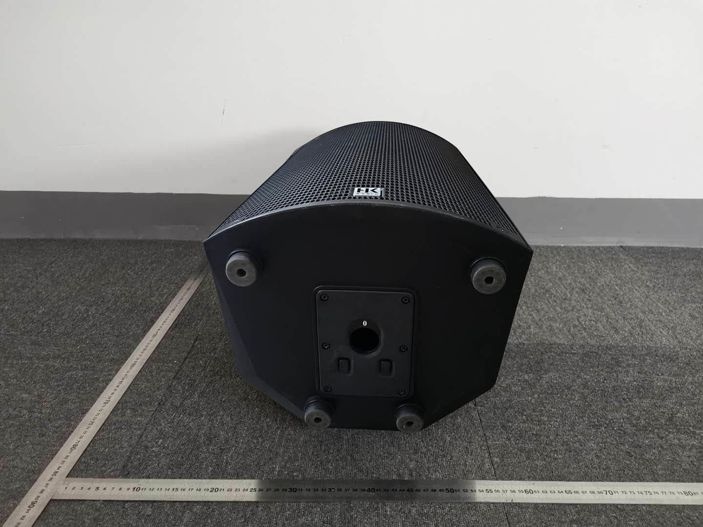
Click to zoom
Application Details
- Equipment Class
- DSS - Part 15 Spread Spectrum Transmitter
- Date of Grant
- Oct 21, 2020
- Application Purpose
- Original Equipment
- Date of Application
- Oct 21, 2020
- Equipment Note
- BLUETOOTH ACTIVE SPEAKER
- Frequency Range
- 2402.00000000 - 2480.00000000
- Company
- Stamer Musikanlagen GmbH
- Country
- Germany
Documents & Files
Document Text
Text extracted from the exhibit documents filed with the FCC. Open a document above to read the original.
Users Manual
Manual 0.9 • English • Français SONAR 112Xi,115XI Important Safety Instructions! Read before connecting! This product has been built by the manufacturer in accordance with IEC 62368-1 and left the factory in safe working order. To maintain this condition and ensure non-risk operation, the user must follow the advice and warning comments found in the operating instructions. If this product shall be used in vehicles, ships or aircraft or at altitudes exceeding 2000 m above sea level, take care of the relevant safety regulations which may exceed the IEC 62368-1 requirements. WARNING: To prevent the risk of fire and shock hazard, do not expose this appliance to moisture or rain. Do not open case – no user serviceable parts inside. Refer service to qualified service personnel. This symbol, wherever it appears, alerts you to the presence of uninsulated dangerous voltage inside the enclosure – voltage that may be sufficient to constitute a risk of shock. This symbol, wherever it appears, alerts you to the presence of externally accessible hazardous voltage. External wiring connected to any terminal marked with this symbol must be a “ready made cable” complying with the manufacturers recommendations, or must be a wiring installed by instructed persons only. This symbol, wherever it appears, alerts you to important operating and maintenance instructions in the accompanying literature. Read the manual. This symbol, wherever it appears, tells you: Take care! Hot surface! To prevent burns you must not touch. All electrical and electronic products including batteries should be disposed of separately from the municipal waste stream via designated collection facilities appointed by the government or the local authorities. Read these instructions. Keep these instructions. Follow all warnings and instructions marked on the product and in this manual. • Do not use this product near water. Do not place the product near water, baths, wash basins, kitchen sinks, wet areas, swimming pools or damp rooms. • Do not place objects containing liquid on the product – vases, glasses, bottles etc. • Clean only with dry cloth. • Do not remove any covers or sections of the housing. • The set operating voltage of the product must match the local mains supply voltage. If you are not sure of the type of power available consult your dealer or local power company. • Before connecting the device, please ensure that the mains supply you are using is equipped with adequate protection against short circuiting and grounding faults when the device is plugged in. • To reduce the risk of electrical shock, the grounding of this product must be maintained. Use only the power supply cord provided with this product, and maintain the function of the center (grounding) pin of the mains connection at any time. Make sure the mains outlet used provides a proper protective ground connection. • Do not defeat the safety purpose of the polarized or grounding-type plug. A polarized plug has two blades with one wider than the other. A grounding type plug has two blades and a third grounding prong. The wide blade or the third prong are provided for your safety. If the provided plug does not fit into your outlet, consult an electrician for replacement of the obsolete outlet. • Protect the power cord from being walked on or pinched particularly at plugs, convenience receptacles, and the point where they exit from the device! Power supply cords should always be handled carefully. Periodically check cords for cuts or sign of stress, especially at the plug and the point where the cord exits the device. • Never use a damaged power cord. • Unplug this product during lightning storms or when unused for long periods of time. • This product can be fully disconnected from mains only by pulling the mains plug at the unit or the wall socket. The product must be placed in such a way at any time, that disconnecting from mains is easily possible. • Fuses are to be replaced exclusively by qualified personnel, and then only with fuses of the proper type and rating. • Refer all servicing to qualified service personnel. Servicing is required when the unit has been damaged in any way, such as: - When the power cord or plug is damaged or frayed. - If liquid has been spilled or objects have fallen into the product. - If the product has been exposed to rain or moisture. - If the product does not operate normally when the operating instructions are followed. - If the product has been dropped or the cabinet has been damaged. • Do not connect external speakers to this product with an impedance lower than the rated impedance given on the product or in this manual. Use only cables with sufficient cross section according to the local safety regulations. • Keep away from direct sunlight. • Do not install near heat sources such as radiators, heat registers, stoves or other devices that produce heat. • This apparatus is for moderate climates areas use, not suitable for use in tropical climates countries. • Do not block any ventilation openings. Install in accordance with manufacturer’s instructions. This product must not be placed in a built-in installation such as a rack unless proper ventilation is provided. • Always allow a cold device to warm up to ambient temperature, when being moved into a room. Condensation can form inside it and damage the product, when being used without warming up. • Do not place naked flame sources, such as lighted candles on the product. • The device must be positioned at least 20 cm/8" away from walls. • Use only with the cart, stand, tripod, bracket or table specified by the manufacturer or sold with the product. When a cart is used, use caution when moving the cart/product combination to avoid injury from tip-over. • Use only accessories recommended by the manufacturer, this applies for all kind of accessories, for example protective covers, transport bags, stands, wall or ceiling mounting equipment. In case of attaching any kind of accessories to …
Text truncated - open the document above for the full version.
Cover Letter(s)
Stamer Musikanlagen GmbH Agent Authorization Company: Stamer Musikanlagen GmbH Address: Magdeburger Str.8-66606 St. Wendel Germany Product Name: ACTIVE SPEAKER Model Number(s): SONAR 112 Xi, SONAR 115 Xi Product Description: BLUETOOTH ACTIVE SPEAKER We authorize MiCOM Labs Inc., 575 Boulder Court, Pleasanton, California 94566, USA, to act on our behalf on all matters concerning the certification of above named equipment. We declare that MiCOM Labs Inc. is allowed to forward all information related to the approval and certification of equipment to the regulatory agencies as required and to discuss any issues concerning the approval application. Any and all acts carried out by MiCOM Labs on our behalf shall have the same effect as acts of our own. Signature: Date: 2020/10/12 Name: Holger Kartes Title: Chief Technical Officer Company: Stamer Musikanlagen GmbH
Cover Letter(s)
Stamer Musikanlagen GmbH Authorization Letter We, (the approval holder) Company name Stamer Musikanlagen GmbH Addresss Magdeburger Str.8-66606 St. Wendel Germany declare that the following representative (agent): Name (person) Bovey Yang Company name Shenzhen STS Test Services Co., Ltd. Addresss 1/F., Building B, Zhuoke Science Park, No.190, Chongqing Road, Fuyong Street, Bao’an District, Shenzhen, Guangdong,China City Shenzhen Country China to act on our behalf on all matters concerning the application and documents submitted to Micom Labs for product certification below Product Description ACTIVE SPEAKER Type or Model(s) SONAR 112 Xi, SONAR 115 Xi Tradename or Brand(s) Attestation: City: Date: Name: (this must be a person) Function: Signature: (or official company stamp) Germany 2020/10/12 Holger Kartes Chief Technical Officer
Cover Letter(s)
Differences Description We Stamer Musikanlagen GmbH state: Product: ACTIVE SPEAKER Model Name: SONAR 112 Xi, SONAR 115 Xi Brand Name: FCC ID: 2AWA3-SONAR1215 The electrical circuit design, layout, components used and internal wiring for above models are identical, Only different in model name. Sincerely, Company: Stamer Musikanlagen GmbH Title: Chief Technical Officer E-mail: [email protected] Name: Holger Kartes Signature
Cover Letter(s)
Stamer Musikanlagen GmbH Office of Engineering Technology Federal Communications Commission 7435 Oakland Mills Road Columbia, MD 21046 USA Date: 2020/10/12 Subject; Request for Confidentiality FCC ID: 2AWA3-SONAR1215 To Whom It May Concern, Pursuant to the provisions of the Commission’s rules Title 47 Sections §0.457 and §0.459, we are requesting the Commission to withhold the following attachment(s) as confidential documents from public disclosure indefinitely. These documents contain detailed system and equipment descriptions and are considered as proprietary information in operation of the equipment. The public disclosure of these documents might be harmful to our company and would give competitors an unfair advantage in the market. Schematic Diagram Block Diagram Parts List Operational Description Tune-up Procedure In additional to above mentioned documents, in order to comply with the marketing regulations in Title 47 CFR §2.803 and the importation rules in Title 47 CFR §2.1204, while ensuring that business sensitive information remains confidential until the actual marketing of newly authorized devices, we request Short Term Confidentiality of the following attachment(s); External Photos Test Setup Photos Internal Photos User Manual For 45 days, pursuant to Public Notice DA 04-1705. OR For 180 days pursuant to KDB 726920 D01. It is our understanding that all measurement test reports, FCC ID label format and correspondence during the certification review process cannot be granted as confidential documents and this information will be available for public review once the grant of equipment authorization is issued. Sincerely, Signature: Name: Holger Kartes Title: Chief Technical Officer
External Photos
Page 1 of 3 Report No.: STS2007333 APPENDIX-PHOTOGRAPHS OF EUT CONSTRUCTIONAL DETAILS Model: SONAR 112 Xi Photo 1 Photo 2 Page 2 of 3 Report No.: STS2007333 Photo 3 Photo 4 Page 3 of 3 Report No.: STS2007333 Photo 5 Photo 6
ID Label/Location Info
Label Size:20*10mm The label is printed on the shell ACTIVE SPEAKER Model name: SONAR 112 Xi FCC ID: 2AWA3-SONAR1215 Size:20*10mm The label is printed on the shell ACTIVE SPEAKER Model name: SONAR 115 Xi FCC ID: 2AWA3-SONAR1215
Internal Photos
Page 1 of 6 Report No.: STS2007333 APPENDIX-PHOTOGRAPHS OF EUT CONSTRUCTIONAL DETAILS Model: SONAR 112 Xi Photo 1 Photo 2 BT Antenna Page 2 of 6 Report No.: STS2007333 Photo 3 Photo 4 Page 3 of 6 Report No.: STS2007333 Photo 5 Photo 6 Page 4 of 6 Report No.: STS2007333 Photo 7 Photo 8 Page 5 of 6 Report No.: STS2007333 Photo 9 Photo 10 Page 6 of 6 Report No.: STS2007333 Photo 11
RF Exposure Info
RF Exposure Report FCC ID: 2AWA3-SONAR1215 RF Exposure Measurement The limit for Maximum Permissible Exposure (MPE) specified in FCC 1.1310 is followed. The gain of the antennas used in the product is extracted from the Antenna data sheets provided and also the maximum total power input to the antenna is measured. Through the Friis transmission formula and the maximum gain of the antenna, we can calculate the distance, away from the product, where the limit of MPE is reached. Although the Friis Transmission formula is far field assumption, the calculated result of that is an over-prediction for near field power density. It is taken as worst case to specify the safety range. RF Exposure Limit According to FCC 1.1310: The criteria listed in the following table shall be used to evaluate the environmental impact of the human exposure to radio-frequency (RF) radiation as specified in 1.1307 (b) Limits for Maximum Permissible Exposure (MPE) F= Frequency in MHz Frequency Range (MHz) Electric Field Strength (V/m) Magnetic Field Strength (A/m) Power Density (mW/cm²) Limits for Occupational / controlled Exposures 300 - 1500 -- -- F/300 1500 – 100000 -- -- 5.0 Limits for General population / Uncontrolled Exposure 300 - 1500 -- -- F/1500 1500 – 100000 -- -- 1.0 Friss Formula Friss Transmission Formula: Pd = (Pout * G) / (4*pi*r²) Where Pd = power density in mW/cm² Pout = output power to antenna in mW G = gain of antenna in linear scale Pi = 3.1416 R = Distance between observation point and the center of radiator in cm If we know the maximum gain of the antenna and the total output power to the antenna, through calculation, we will know MPE value at distance 20cm. EUT Operation condition EUT was enabled to transmit and receive at lowest, middle and highest channels. Classification The antenna of this product, under normal use condition, is at least 20cm away from the body of the user. Warning statement to the user for keeping at least 20cm or more separation distance from the antenna should be included in the User manual. So, this device is classified as Mobile device. BT4.2+EDR Mode 2402-2480MHz Detector PEAK GFSK LOW CH -2±1dBm MID CH -3±1dBm HIGH CH -4±1dBm π/4-DQPSK -4±1dBm 8DPSK -3.5±1dBm ANT Gain (G) Antenna gain : 0dBi (gain of antenna in linear scale=1) GFSK12402 -10.79430.00016 1 π/4-DQPSK12402 -30.50120.00010 1 8DPSK12402 -2.50.56230.00011 1 Power Density (mW/cm²) Limit (mW/cm²) ANT Gain(gain of antenna in linear scale) Protocol Channel Frequency (MHz) Output Power to Antenna (dBm) Output Power to Antenna (mW) According to the maximum gain of the antenna and the total output power to theantenna, through calculation, we will know max MPE value 0.00016 t distance 20cm. This is less than the limit 1. Compliance the RF exposure requirement.
Test Report
Any reproduction of this document must be done in full. No single part of this document may be reproduced without permission from STS, All Test Data Presented in this report is only applicable to presented Test sample. Shenzhen STS Test Services Co., Ltd. A 1/F, Building B, Zhuoke Science Park, No.190 Chongqing Road, HepingShequ, Fuyong Sub-District, Bao’an District, Shenzhen, Guang Dong, China TEL: +86-755 3688 6288 FAX: +86-755 3688 6277 E-mail:[email protected] RADIO TEST REPORT Report No.: STS2007333W01 Issued for Stamer Musikanlagen GmbH Magdeburger Str.8-66606 St. Wendel Germany Product Name: ACTIVE SPEAKER Brand Name: Model Name: SONAR 112 Xi Series Model: SONAR 115 Xi FCC ID: 2AWA3-SONAR1215 Test Standard: FCC Part 15.247 S T L A B S Page 2 of 73 Report No.: STS2007333W01 TEST RESULT CERTIFICATION Applicant’s Name ................... : Stamer Musikanlagen GmbH Address .................................. : Magdeburger Str.8-66606 St. Wendel Germany Manufacturer's Name ............. : Ningbo Tonwel Audio Co., LTD Address .................................. : 499 YingDong North Road, Zhanqi Town, Ningbo, China 315144 Product Description Product Name ........................ : ACTIVE SPEAKER Brand Name ......................... : Model Name ........................... : SONAR 112 Xi Series Model .......................... : SONAR 115 Xi Test Standards ....................... : FCC Part15.247 Test Procedure ....................... : ANSI C63.10-2013 This device described above has been tested by STS, the test results show that the equipment under test (EUT) is in compliance with the FCC requirements. And it is applicable only to the tested sample identified in the report. This report shall not be reproduced except in full, without the written approval of STS, this document may be altered or revised by STS, personal only, and shall be noted in the revision of the document. Date of Test ................................ : Date of receipt of test item .......... : 27 July 2020 Date (s) of performance of tests . : 27 July 2020 ~ 06 Aug. 2020 Date of Issue .............................. : 06 Aug. 2020 Test Result .................................. : Pass Testing Engineer : (Chris Chen) Technical Manager : (Sean she) Authorized Signatory: (Vita Li) Page 3 of 73 Report No.: STS2007333W01 Table of Contents Page 1. SUMMARY OF TEST RESULTS 6 1.1 TEST FACTORY 7 1.2 MEASUREMENT UNCERTAINTY 7 2. GENERAL INFORMATION 8 2.1 GENERAL DESCRIPTION OF THE EUT 8 2.2 DESCRIPTION OF THE TEST MODES 10 2.3 FREQUENCY HOPPING SYSTEM REQUIREMENTS 10 2.4 TABLE OF PARAMETERS OF TEST SOFTWARE SETTING 12 2.5 BLOCK DIAGRAM SHOWING THE CONFIGURATION OF SYSTEM TESTED 12 2.6 DESCRIPTION OF NECESSARY ACCESSORIES AND SUPPORT UNITS 13 2.7 EQUIPMENTS LIST 14 3. EMC EMISSION TEST 15 3.1 CONDUCTED EMISSION MEASUREMENT 15 3.2 RADIATED EMISSION MEASUREMENT 19 4. CONDUCTED SPURIOUS & BAND EDGE EMISSION 31 4.1 LIMIT 31 4.2 TEST PROCEDURE 31 4.3 TEST SETUP 31 4.4 EUT OPERATION CONDITIONS 31 4.5 TEST RESULTS 32 5. NUMBER OF HOPPING CHANNEL 47 5.1 LIMIT 47 5.2 TEST PROCEDURE 47 5.3 TEST SETUP 47 5.4 EUT OPERATION CONDITIONS 47 5.5 TEST RESULTS 48 6. AVERAGE TIME OF OCCUPANCY 49 6.1 LIMIT 49 6.2 TEST PROCEDURE 49 6.3 TEST SETUP 49 6.4 EUT OPERATION CONDITIONS 49 6.5 TEST RESULTS 50 Page 4 of 73 Report No.: STS2007333W01 Table of Contents Page 7. HOPPING CHANNEL SEPARATION MEASUREMEN 56 7.1 LIMIT 56 7.2 TEST PROCEDURE 56 7.3 TEST SETUP 56 7.4 EUT OPERATION CONDITIONS 56 7.5 TEST RESULTS 57 8. BANDWIDTH TEST 63 8.1 LIMIT 63 8.2 TEST PROCEDURE 63 8.3 TEST SETUP 63 8.4 EUT OPERATION CONDITIONS 63 8.5 TEST RESULTS 64 9. OUTPUT POWER TEST 70 9.1 LIMIT 70 9.2 TEST PROCEDURE 70 9.3 TEST SETUP 70 9.4 EUT OPERATION CONDITIONS 70 9.5 TEST RESULTS 71 10. ANTENNA REQUIREMENT 72 10.1 STANDARD REQUIREMENT 72 10.2 EUT ANTENNA 72 Page 5 of 73 Report No.: STS2007333W01 Revision History Rev. Issue Date Report NO. Effect Page Contents 00 06 Aug. 2020 STS2007333W01 ALL Initial Issue Page 6 of 73 Report No.: STS2007333W01 1. SUMMARY OF TEST RESULTS Test procedures according to the technical standards: KDB 558074 D01 15.247 Meas Guidance v05r02. FCC Part 15.247,Subpart C Standard Section Test Item Judgment Remark 15.207 Conducted Emission PASS -- 15.247(a)(1) Hopping Channel Separation PASS -- 15.247(a)(1)&(b)(1) Output Power PASS -- 15.209 Radiated Spurious Emission PASS -- 15.247(d) Conducted Spurious & Band Edge Emission PASS -- 15.247(a)(1)(iii) Number of Hopping Frequency PASS -- 15.247(a)(1)(iii) Dwell Time PASS -- 15.247(a)(1) Bandwidth PASS -- 15.205 Restricted bands of operation PASS -- Part 15.247(d)/part 15.209(a) Band Edge Emission PASS -- 15.203 Antenna Requirement PASS -- NOTE: (1) ‘N/A’ denotes test is not applicable in this Test Report. (2) All tests are according to ANSI C63.10-2013. Page 7 of 73 Report No.: STS2007333W01 1.1 TEST FACTORY SHENZHEN STS TEST SERVICES CO., LTD Add. : A 1/F, Building B, Zhuoke Science Park, No.190 Chongqing Road, HepingShequ, Fuyong Sub-District, Bao’an District, Shenzhen, Guang Dong, China FCC test Firm Registration Number: 625569 IC test Firm Registration Number: 12108A A2LA Certificate No.: 4338.01 1.2 MEASUREMENT UNCERTAINTY The reported uncertainty of measurement y ±U, where expended uncertainty U is based on a standard uncertainty multiplied by a coverage factor of k=2, providing a level of confidence of approximately 95 %. No. Item Uncertainty 1 RF output power, conducted ±0.68dB 2 Unwanted Emissions, conducted ±2.988dB 3 All emissions, radiated 30-1GHz ±5.6dB 4 All emissions, radiated 1G-6GHz ±5.5dB 5 All emissions, radiated>6G ±5.8dB 6 Conducted Emission (9KHz-150KHz) ±3.37dB 7 Conducted Emission (150KHz-30MHz) ±3.83dB Page 8 of 73 Report No.: STS2007333W01 2. GENERAL INFORMATION 2.1 GENERAL DESCRIPTION OF THE EUT Product Name ACTIVE SPEAKER Trade Name Model Name SONAR 112 Xi Series Model SONAR 115 Xi Model Difference Only different in model name Channel List Please refer to the Note 2. Bluetooth Frequency:2…
Text truncated - open the document above for the full version.
Test Setup Photos
Page 1 of 2 FCC ID: 2AWA3-SONAR1215 DSS Setup photo Model name: SONAR 112 Xi DSS conduction DSS radiation L Page 2 of 2 FCC ID: 2AWA3-SONAR1215 DSS radiation H
Contact Information
Applicant
Holger Kartes(Chief Technical Officer)
Technical Contact
Test Firm
SHENZHEN STS TEST SERVICES CO.,LTD.Bovey Yang
[email protected]+86 755-36886288
Technical Specifications
| # | Rule Parts | Frequency Range | Power Output |
|---|---|---|---|
| 1 | 15C | 2.40 GHz - 2.48 GHz | 697.00 µW |
Other Applications from Stamer Musikanlagen GmbH
2AWA3-POLAR8MK2
Apr 30, 2026Sound Column Audio System
Equipment Class
DSS - Part 15 Spread Spectrum Transmitter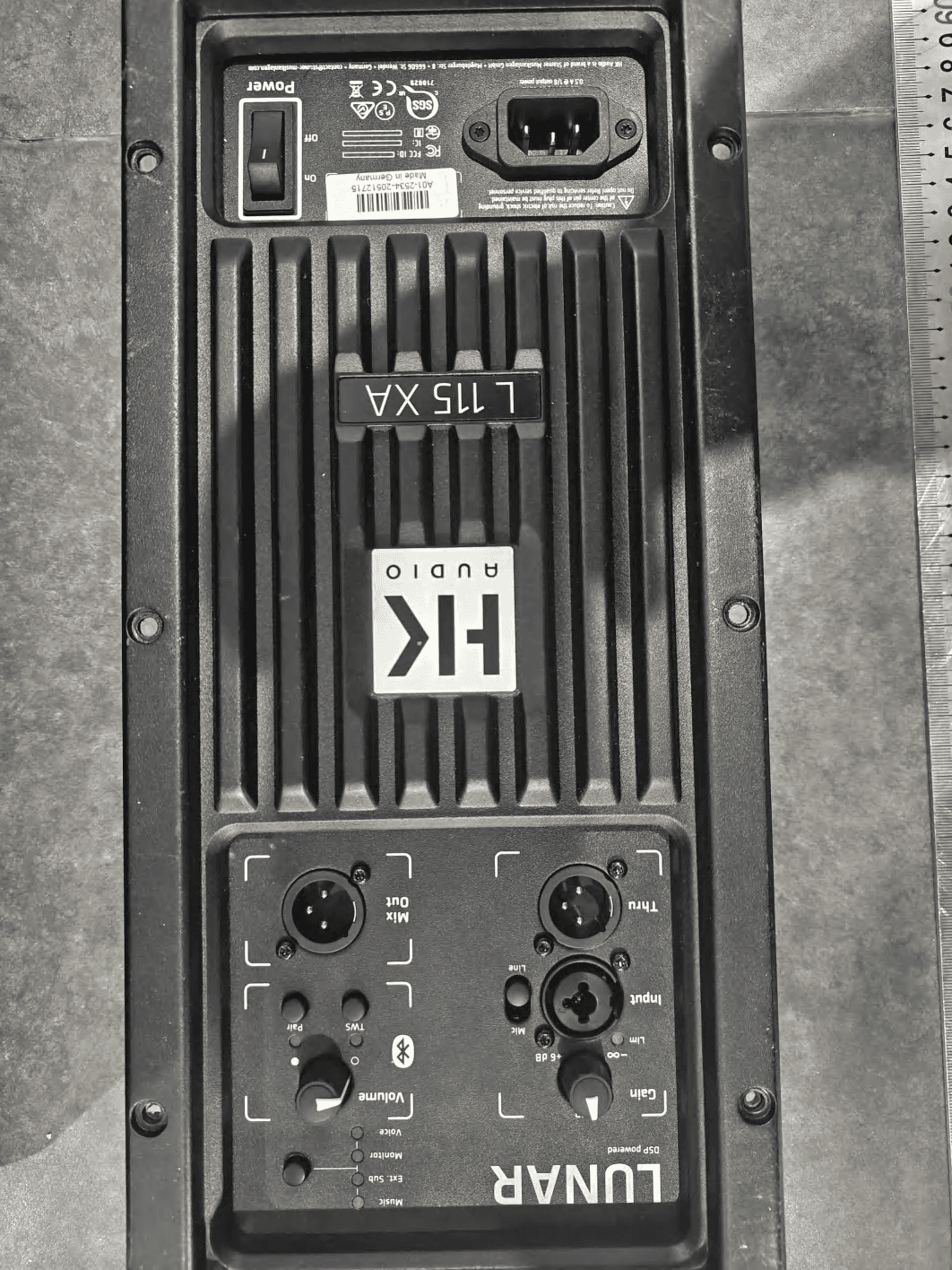
2AWA3-LUNAR
Mar 17, 2026Active speaker
Equipment Class
DSS - Part 15 Spread Spectrum Transmitter