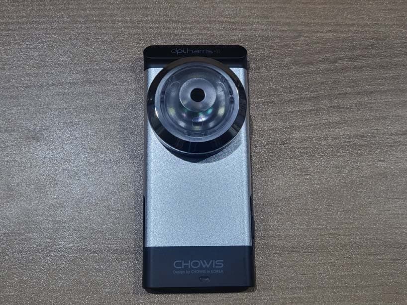
2AWA4CMA-1030Mobile skin/hair/scalp analyzer
CHOWIS Co., Ltd.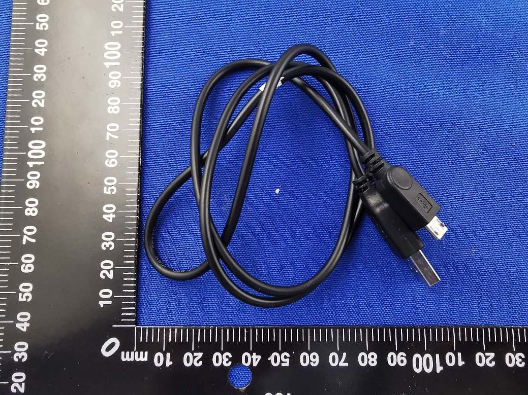
Click to zoom
Application Details
- Equipment Class
- DTS - Digital Transmission System
- Date of Grant
- Jul 07, 2020
- Application Purpose
- Original Equipment
- Date of Application
- Jul 07, 2020
- Equipment Note
- Mobile skin/hair/scalp analyzer
- Frequency Range
- 2402.00000000 - 2480.00000000
- Company
- CHOWIS Co., Ltd.
- Country
- South Korea
Documents & Files
Document Text
Text extracted from the exhibit documents filed with the FCC. Open a document above to read the original.
Users Manual
DEVICE DESCRIPTIONSPECIFICATIONS TURN ON & OFF DEVICE USING APP HOW TO MEASURE USING APP HOW TO ANALYZE INSTALLING THE DPI HAIR PICO APP1. Open App Store/Play Store and search “Chowis.” 2. Select DermoPico Hair app and tap get to install. CONNECTING DEVICE TO PHONE 1. Turn on Bluetooth on your phone.2. Open DermoPico Hair app.3. Choose Product ID of device to connect via bluetooth.4. Follow device initialization instructions, press start.NOTE: If connection was successful, Bluetooth indicator will change to blue, if not, it is grey. DERMO PICO HAIR ANALYSIS 1. At the Home Screen, tap Start button to open Analysis. 2. There are 2 choices; Customer and Quick Analysis. Customer - Adding new customer before analysis. Quick Analysis - minor info needed then go to analyze. REGISTERING NEW CUSTOMER 1. Select Customer and tap on “ New Customer ” button. 2. Fill up required data on fields, all fields with asterisk “ * ” are all important and must not be blank. Then press “ Save ” button. 3. Select the registered customer on the table and then press “ Analysis ” button at the bottom. 1. DermoPico Hair Measurements a. Total Program covers all measurements - Scalp Hydration - Scalp Sebum - Hair Density - Dead Skin Cells - Scalp Impurities 3. How to Capture Images. a. Tap specific measurement on the screen b. Place handset on the head c. Make use lens touches the scalp of the head d. Press Capture button to take image, do not move the headset positions away from the head.NOTE: All measurements can have the same image taken. Magnification x30 Battery 250mAh Li-PolymerProduct size 46 mm(width) × 106 mm(height) × 31 mm(depth)Product weight 75g - Device Only Analysis result Index per measurement (0–99)Measurement 1. Moisture sensor 2. Magnetic attachment3. Serial Number and Product ID4. Micro USB port (Charging) 5. Non-removable lens 6. Power Switch (On/Off)7. Light Indicator 1 2 3 5 6 7 44 Attach Metal Guide to the phone Mount device to the magnet 1. Analyzing after all measurements a. Tap on every menu on tab to show measurements b. On every tab analyze one by one.2. Shows all results here a. Comparison, compare taken image with professional data set that includes different range of images.3. Full Results a. Tap results button to show results b. Results of all measurements will be shown in the horizontal bar graph. c. In addition, users can check the results in pie chart on the next page.1. Charge device using USB charger, Charging time is 2 hours maximum.2. To turn on the device, press the power switch of the dpi Harris device for 3 seconds until LED light blinks3. To turn off the device, press the power switch for 3 seconds until LED light blinks4. Put paper film guide on your phone and attach the metal guide5. Align the device’s eyepiece to camera lens. 6. Attach the dpi Harris device on the metal guide of the smart phone ( or the phone cover ) metal guide Me tal to one m art p h one ( or t h ou nt dev ice t h e magnet t he metal guide of cove r ) For more information visit us at www.chowis.com. Chowis Co., Ltd. Tel: +82 31 706 7950 / Fax: +82 31 272 7950 Address: A1301-2, 184, Jungbu-daero, Giheung-gu, Yongin-si, Gyeonggi-do, Republic of Korea, 17095 E-mail: [email protected] Skype ID: Hello Chowis Skype QUICK MANUAL Model Name: CMA-030-A SCALP SEBUM SCALP IMPURITIES SCALP HYDRATION DEAD SCALP CELL ay eo e set that inc Oeeyt oe. lt f l l HAIR DENSITY s p lt f l l su lts su lts p sults p lt f ll This device complies with part 15 of the FCC rules and RSS-247 of Industry Canada. Operation is subject to the following two conditions: (1) this device may not cause harmful interference, and (2) this device must accept any interference received, including interference that may cause undesired operation.NOTE: The manufacturer is not responsible for any radio or TV interference caused by unauthorized modifications to this equipment. Such modifications could void the user’s authority to operate the equipment.NOTE: This equipment has been tested and found to comply with the limits for a Class B digital device, pursuant to part 15 of the FCC Rules. These limits are designed to provide reasonable protection against harmful interference in a residential installation. This equipment generates uses and can radiate radio frequency energy and, if not installed and used in accordance with the instructions, may cause harmful interference to radio communications. However, there is no guarantee that interference will not occur in a particular installation. If this equipment does cause harmful interference to radio or television reception, which can be determined by turning the equipment off and on, the user is encouraged to try to correct the interference by one or more of the following measures: - Reorient or relocate the receiving antenna. - Increase the separation between the equipment and receiver. - Connect the equipment into an outlet on a circuit different from that to which the receiver is connected. - Consult the dealer or an experienced radio/TV technician for help. - This device and its antenna(s) must not be co-located or operating in conjunction with any other antenna or transmitter.
Users Manual
DEVICE DESCRIPTIONSPECIFICATIONS TURN ON DEVICE USING APP HOW TO MEASURE USING APP HOW TO ANALYZE 1. Charge device using USB charger, Charging time is 2 hours maximum.2. Press switch button of the dpi Viso device for 3 seconds until LED light blinks.2. Put paper guide on your phone and attach magnet on.3. Attach the dpiViso device on magnet. INSTALLING THE DPIVISO PICO APP 1. Open App Store and type “Chowis.” or scan QR code:2. Select DermoPico Skin app and install. CONNECTING DEVICE TO PHONE 1. Turn on Bluetooth on your phone.2. Open Dermo Pico app.3. Choose MAC code of device to connect.4. After connecting device, press start.5. Select Quick Diagnosis for quick usage.NOTE: If connection was successful, Bluetooth indicator will change to pink if not it is grey. DERMO PICO SKIN ANALYSIS 1. At the Home Screen, tap Start button to open Analysis. 2. There are 2 choices; Customer and Quick Analysis. Customer - Adding new customer before diagnosis. Quick Analysis - Directly go to diagnosis.REGISTERING NEW CUSTOMER 1. Select Customer and tap on “New Customer” button. 2. Fill up required data on fields, all fields with asterisk “ * ” are all important and must not be blank. Then press “Save” button. 3. Select the registered customer on the table and then press “Analysis” button at the bottom. HOW TO MEASURE HYDRATION 1. Select Hydration on the app and place Moisture sensor on the forehead (T-zone) or the U-zone. 2. Place Moisture sensor on the T-zone or the U-zone.HOW TO ANALYZE HYDRATION 1. Dab end of the pink Sebum Indicator T-zone on the forehead and U-zone to the cheeck area for 3 seconds. 2. Select Sebum botton below and take an image of the Sebum Indicator, tap U-zone and T-zone for capturing. Make sure to include all pink areas on the capture. HOW TO ANALYZE ANALYZING PORE, WRINKLEAND IMPURITIES 1. Tap specific icon on the app for analyzing, take image of the Pores, Wrinkles and Impurities RESULTS AFTER MEASUREMENTS 1. After all measurements, tap Results button below and app will show graph of all analysis results. 2. Slide left to see more of the result. 2 OR MORE ANALYSIS RESULTS 1. Open main screen page. 2. Press start, customer and choose customer name from list. 3. Click the round pink icon on the right to view analysis results save. 4. Select the dates you want to compare from. 5. Press compare button and view a linear graph of comparison and results. QUICK MANUAL Model Name: CMA-010-A 1. Moisture sensor 2. Magnetic attachment3. Micro-USB B port4. Serial Number 5. Non-removable lens 6. Switch On/Off7. Light Indicator 1 2 3 5 6 7 3 4 Magnification 10×Battery 250 Lithium-ionbatteryProduct size 106 mm × 46 mm × 37 mmProduct weight 60 g Analysis result Index per measurement (0–99)Measurement START SETTINGS CUSTOMER QUICK DIAGNOSIS hydration wrinkle pores impurities sebum For more information visit us at www.chowis.com. Chowis Co., Ltd. Tel: +82 31 706 7950 / Fax: +82 31 272 7950 Address: A1301-2, 184, Jungbu-daero, Giheung-gu, Yongin-si, Gyeonggi-do, Republic of Korea, 17095 E-mail: [email protected] Skype ID: Hello Chowis Skype This device complies with part 15 of the FCC rules and RSS-247 of Industry Canada. Operation is subject to the following two conditions: (1) this device may not cause harmful interference, and (2) this device must accept any interference received, including interference that may cause undesired operation.NOTE: The manufacturer is not responsible for any radio or TV interference caused by unauthorized modifications to this equipment. Such modifications could void the user’s authority to operate the equipment.NOTE: This equipment has been tested and found to comply with the limits for a Class B digital device, pursuant to part 15 of the FCC Rules. These limits are designed to provide reasonable protection against harmful interference in a residential installation. This equipment generates uses and can radiate radio frequency energy and, if not installed and used in accordance with the instructions, may cause harmful interference to radio communications. However, there is no guarantee that interference will not occur in a particular installation. If this equipment does cause harmful interference to radio or television reception, which can be determined by turning the equipment off and on, the user is encouraged to try to correct the interference by one or more of the following measures: - Reorient or relocate the receiving antenna. - Increase the separation between the equipment and receiver. - Connect the equipment into an outlet on a circuit different from that to which the receiver is connected. - Consult the dealer or an experienced radio/TV technician for help. - This device and its antenna(s) must not be co-located or operating in conjunction with any other antenna or transmitter.
Cover Letter(s)
CHOWIS Co., Ltd. Date: 24 June, 2020 To: Federal Communications Commission, Authorization & Evaluation Division, 7435 Oakland Mills Road, Columbia, MD 21046 To Whom It May Concern: CHOWIS Co., Ltd., the undersigned, hereby authorizes Mr. Wu Xuewen from Shenzhen BALUN Technology Co., Ltd., to act on the behalf of the CHOWIS Co., Ltd. solely in matters relating to the application for an FCC equipment authorization for FCC ID: 2AWA4CMA-1030 including the signing of documents in connection with this Application. Necessary acts carried out by Shenzhen BALUN Technology Co., Ltd. in connection with the Application shall have the same effect as acts of CHOWIS Co., Ltd. CHOWIS Co., Ltd. also hereby certify that no party to this application is subject to a denial of benefits, including FCC benefits, pursuant to Section 5301 of the Anti-Drug Abuse Act of 1988, 21 U.S.C. Section 862. Yours Sincerely, (signature) Print name: Choi Won Suk Title:CEO CHOWIS Co., Ltd.
Cover Letter(s)
CHOWIS Co., Ltd. Date: 24 June, 2020 To: Federal Communications Commission, Authorization & Evaluation Division, 7435 Oakland Mills Road, Columbia, MD 21046 RE: CHOWIS Co., Ltd. FCC ID: 2AWA4CMA-1030 FCC Certification Confidentiality Request Gentlemen: This letter is to comply with 47 CFR 0.457 and 0.459 pertaining to confidentiality material. CHOWIS Co., Ltd. requests that the following documents regarding this submission for FCC ID: 2AWA4CMA- 1030 be kept Long-Term confidential: Exhibit Type File Name Block Diagram Block Diagram.pdf Schematics Schematics.pdf Operational Description Operational Description.pdf Those documents contain detailed system and equipment description and related information about the product which CHOWIS Co., Ltd. considers to be confidential proprietary, a custom design and, otherwise, not releasable to the general public. Since this design is a basis form which future technological products will evolve, CHOWIS Co., Ltd. considers this information would be of benefit to its competitors, and that the disclosure of the information in these documents would give competitors an unfair advantage in the market. Thank you for your attention to this matter. Yours Sincerely, (signature) Print name: Choi Won Suk Title:CEO CHOWIS Co., Ltd.
External Photos
Annex No.: BL-EC19C0007-AW 1 / 8 EUT EXTERNAL PHOTOS CMA-030 FRONT VIEW OF EUT REAR VIEW OF EUT Annex No.: BL-EC19C0007-AW 2 / 8 LEFT SIDE VIEW OF EUT RIGHT SIDE OF EUT Annex No.: BL-EC19C0007-AW 3 / 8 TOP VIEW OF EUT BOTTOM VIEW OF EUT Annex No.: BL-EC19C0007-AW 4 / 8 CMA-010 FRONT VIEW OF EUT REAR VIEW OF EUT Annex No.: BL-EC19C0007-AW 5 / 8 LEFT SIDE VIEW OF EUT RIGHT SIDE OF EUT Annex No.: BL-EC19C0007-AW 6 / 8 TOP VIEW OF EUT BOTTOM VIEW OF EUT Annex No.: BL-EC19C0007-AW 7 / 8 Accessory-Power Adapter CLOSE-UP Annex No.: BL-EC19C0007-AW 8 / 8 Accessory-USB Cable
ID Label/Location Info
Label location:
Internal Photos
Annex No.: BL-EC19C0007-AI 1 / 4 EUT INTERNAL PHOTOS EUT UNCOVER VIEW EUT UNCOVER VIEW Annex No.: BL-EC19C0007-AI 2 / 4 EUT UNCOVER VIEW MAIN BOARD TOP VIEW Chip Antenna RF Chip Annex No.: BL-EC19C0007-AI 3 / 4 MAIN BOARD REAR VIEW b Battery Photo (FRONT) Annex No.: BL-EC19C0007-AI 4 / 4 Battery Photo (REAR)
RF Exposure Info
RF Exposure Evaluation for FCC ID: 2AWA4CMA‐1030 Refer user manual this device is a mobile skin/hair/scalp analyzer, and this device was designed used in portable devices that the minimum distance between human’s body is 5mm. Based on the 47CFR 2.1093, this device belongs to portable device. The definition of the category as following: Portable Derives: CFR Title 47 §2.1093(b) (b) For purposes of this section, a portable device is defined as a transmitting device designed to be used so that the radiating structure(s) of the device is/are within 20 centimeters of the body of the user. FCC KDB 447498 D01 General RF Exposure Guidance v06 Limit Unless specifically required by the published RF exposure KDB procedures, standalone 1‐g head or body and 10‐g extremity SAR evaluation for general population exposure conditions, by measurement or numerical simulation, is not required when the corresponding SAR Test Exclusion Threshold condition, listed below, is satisfied. These test exclusion conditions are based on source‐ based time‐averaged maximum conducted output power of the RF channel requiring evaluation, adjusted for tune‐up tolerance, and the minimum test separation distance required for the exposure conditions. The minimum test separation distance is determined by the smallest distance from the antenna and radiating structures or outer surface of the device, according to the host form factor, exposure conditions and platform requirements, to any part of the body or extremity of a user or bystander. The 1‐g and 10‐g SAR test exclusion thresholds for 100 MHz to 6 GHz at test separation distances ≤ 50 mm are determined by: [(max. power of channel, including tune‐up tolerance, mW) / (min. test separation distance, mm)] · [√f(GHz) ] ≤ 3.0 for 1‐g SAR and ≤ 7.5 for 10‐g extremity SAR Where • f (GHz) is the RF channel transmit frequency in GHz • Power and distance are rounded to the nearest mW and mm before calculation • The result is rounded to one decimal place for comparison The test exclusions are applicable only when the minimum test separation distance is ≤ 50 mm and for transmission frequencies between 100 MHz and 6 GHz. When the minimum test separation distance is < 5 mm, a distance of 5 mm is applied to determine SAR test exclusion. Test data BLUETOOTH Mode GFSK (BLE) Low Channel Middle Channel High Channel Peak Power (dBm) -3.19 -3.68 -4.23 Note: This report listed the worst case peak power value, please refer to RF test report for more details. Turn-up power Mode Range (dBm) Bluetooth (-4.50) – (-3.00) FCC exclusion condition= [0.5 mW/5 mm] · [√2.402 GHz] = 0.155 < 3.0 RF Exposure Evaluation Result: Pass Note: More power data, Please refer to the RF report.
Test Report
Report No.: BL-EC19C0007-601 2 / 51 Revision History Version Issue Date Revisions Content Rev. 01 Jun. 29, 2020 Initial Issue Rev. 02 Jul. 02, 2020 Correction applicant and manufacturer information TABLE OF CONTENTS ADMINISTRATIVE DATA (GENERAL INFORMATION) .......................................................................... 5 1.1 Identification of the Testing Laboratory ....................................................................................... 5 1.2 Identification of the Responsible Testing Location ...................................................................... 5 1.3 Laboratory Condition ................................................................................................................... 5 1.4 Announce .................................................................................................................................... 5 PRODUCT INFORMATION ...................................................................................................................... 6 2.1 Applicant Information ................................................................................................................... 6 2.2 Manufacturer Information ............................................................................................................ 6 2.3 Factory Information ..................................................................................................................... 6 2.4 General Description for Equipment under Test (EUT) ................................................................ 6 2.5 Technical Information .................................................................................................................. 7 2.6 Additional Instructions ................................................................................................................. 8 SUMMARY OF TEST RESULTS .............................................................................................................. 9 3.1 Test Standards ............................................................................................................................ 9 3.2 Verdict ......................................................................................................................................... 9 GENERAL TEST CONFIGURATIONS ................................................................................................... 10 4.1 Test Environments .................................................................................................................... 10 4.2 Test Equipment List ................................................................................................................... 10 4.3 Measurement Uncertainty ......................................................................................................... 11 4.4 Description of Test Setup .......................................................................................................... 12 4.4.1 For Antenna Port Test ............................................................................................................... 12 4.4.2 For AC Power Supply Port Test ................................................................................................ 12 4.4.3 For Radiated Test (Below 30 MHz) ........................................................................................... 13 4.4.4 For Radiated Test (30 MHz-1 GHz) .......................................................................................... 13 4.4.5 For Radiated Test (Above 1 GHz) ............................................................................................. 14 4.5 Measurement Results Explanation Example ............................................................................. 15 Report No.: BL-EC19C0007-601 3 / 51 4.5.1 For conducted test items: .......................................................................................................... 15 4.5.2 For radiated band edges and spurious emission test: ............................................................... 15 TEST ITEMS ........................................................................................................................................... 16 5.1 Antenna Requirements .............................................................................................................. 16 5.1.1 Relevant Standards ................................................................................................................... 16 5.1.2 Antenna Anti-Replacement Construction .................................................................................. 16 5.1.3 Antenna Gain ............................................................................................................................ 16 5.2 Output Power ............................................................................................................................ 17 5.2.1 Test Limit ................................................................................................................................... 17 5.2.2 Test Setup ................................................................................................................................. 17 5.2.3 Test Procedure .......................................................................................................................... 17 5.2.4 Test Result ................................................................................................................................ 18 5.3 Occupied Bandwidth ................................................................................................................. 19 5.3.1 Limit ........................................................................................................................................... 19 5.3.2 Test Setup ..............................................................................................................................…
Text truncated - open the document above for the full version.
Test Setup Photos
Annex No.: BL-EC19C0007-AR TEST SETUP PHOTOS 1 Radiated Test Photo Below 30 MHz 30 MHz-1 GHz Annex No.: BL-EC19C0007-AR Close-Up Above 1GHz Annex No.: BL-EC19C0007-AR Close-Up 2 Conducted Emissions Test Photo 1 Annex No.: BL-EC19C0007-AR Test Photo 2 3 Conducted Test Photo Conducted Test-BLE
Contact Information
Applicant
Choi Won Suk
Test Firm
Shenzhen BALUN Technology Co., Ltd.Hanson Lin
[email protected]86-755-66833830
Technical Specifications
| # | Rule Parts | Frequency Range | Power Output |
|---|---|---|---|
| 1 | 15C | 2.40 GHz - 2.48 GHz | 480.00 µW |
Other Applications from CHOWIS Co., Ltd.
2AWA4CMA2-030
Apr 11, 2023Mobile Skin/Hair Analyzer
Equipment Class
DTS - Digital Transmission System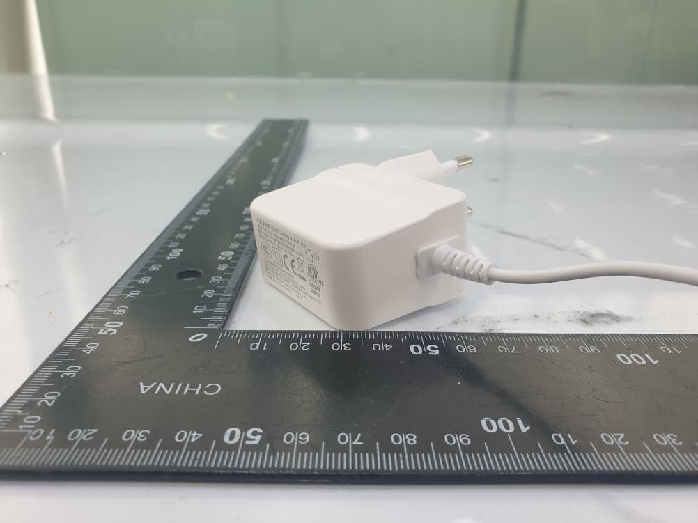
Oct 30, 2020
Equipment Class
DTS - Digital Transmission System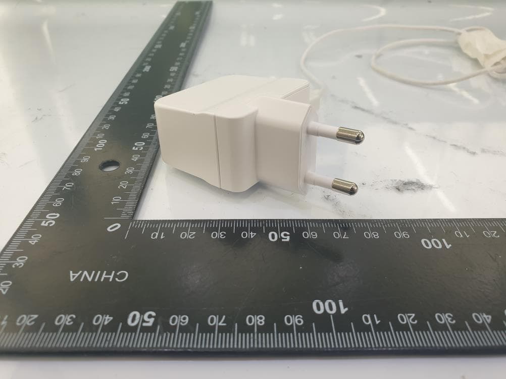
Oct 30, 2020
Equipment Class
DTS - Digital Transmission System