2AWAS-910-00086B25 4T4R 160W Radio Unit
Mavenir Systems Inc
Click to zoom
Application Details
- Equipment Class
- PCB - PCS Licensed Transmitter
- Date of Grant
- Jul 14, 2021
- Application Purpose
- Original Equipment
- Date of Application
- Jul 13, 2021
- Equipment Note
- B25 4T4R 160W Radio Unit
- Frequency Range
- 1940.00000000 - 1985.00000000
- Company
- Mavenir Systems Inc
- Country
- United States
Documents & Files
Document Text
Text extracted from the exhibit documents filed with the FCC. Open a document above to read the original.
Users Manual
B25 4T4R Hardware Installation Manual Version 0.1 2021/5/12 About this document Purpose This document provides hardware installation instructions for B25 4T4R Procedures are provided for RRH handling, mounting, grounding, powering, and cabling. Safety information For your safety, this document contains safety statements. Safety statements are given at points where risks of damage to personnel, equipment, and operation may exist. Failure to follow the directions in a safety statement may result in serious consequences. Intended audience This document is intended for customers installing B25 4T4R Safety labels The safety alert symbol is used on product labels and in this document to alert the user to important safety instructions. How to use this document Prior to installing the radio, the installer should be familiar with the safety precautions, warnings, and product conformance statements. Required tools and materials recommended for installation, and a process checklist, are listed in Chapter “Tools, materials, and checklists” . The RRH installation instructions begin with Chapter “Transport, mount, and ground the radio” which provides mounting instructions for the radio. After it is mounted into position, the RRH can be connected to the network in accordance with the instructions given in Chapter “Connect interfaces” . This connection is made via fiber optic cables. In addition, instructions for connecting user and power alarms are provided in this chapter. Next, instructions to connect the radio to its power source is given in Chapter “Finish the installation” . The power source is DC power provided from an external power Converteror DC generator. Conventions used In this document, all parts are described as they are shipped. Metric parts are specified in metric units. Non-metric parts are specified in non- metric units. Lengths and other measurements are given in metric units, with non-metric units given as equivalents for use in non-metric markets. For manufactured parts, the following system of conventions is used: •Metric sizes of nuts, bolts, flat washers, and lock washers are identified by an uppercase letter M followed immediately by asize in millimeters (example: M10) •American fractional sizes of nuts, bolts, anchor bolts, and washers are identified by a number followed immediately by a double apostrophe (example: 3/8"). In the case of lengths measured in feet, "2 feet" is used rather than "2'" so that the single apostrophe is notoverlooked. The illustrations in this document do not contain all details and exceptions, but are rather intended to highlight main points. Dimensions are usually shown in millimeters, with inches in parenthesis. As an example, 680.0 (26.77) equals 680 millimeters or 26.77 inches. Wire gauges are specified in metric units. Equivalent sizes in the American Wire Gauge (AWG) system are given in the following table. Converteror DC generator. Standard cross-sections and wire diameter of round copper conductors 1 1Safety Structure of safety statements Overview This topic describes the components of safety statements that appear in this document. General structure Safety statements include the following structural elements: Safety General precautions for installation procedures 2 2Product overview Functional description B25 project uses 3GPP bands 25 (working band: TX:1930-1995MHz, RX:1850-1915MHz), which provides the RF transceiver, power amplifiers and filter functions. I provide four TX path and four RX path. B25 includes: •Initially supporting LTE only, but software upgradeable to support NR and NB-IoT, •Two fronthaul optical SFP ports capable of supporting 10G and 25G Ethernet, •O-RAN-compliant fronthaul, •IEEE 1588 and SyncEfor time and frequency reference, •AISG v3.0-compliant DC power and control for external RETs and TMAs, •4 dry contact external alarm inputs, •-48V DC input power. FCC Related Statements This equipment has been tested and found to comply with the limits for a Class A digitaldevice, pursuant to Part 15 of the FCC Rules. These limits are designed to providereasonable protection against harmful interference when the equipment is operated ina commercial environment. This equipment generates, uses, and can radiate radiofrequencyenergyand,ifnotinstalledandusedinaccordancewiththeinstructionmanual,may cause harmful interference to radio communications. Operation of this equipmentIn a residential area is likely to cause harmful interference in which case the user will berequired to correct the interference at his own expense. Operation of this equipment in a residential area is likely to cause harmful interference in which case the user will be required to correct the interference at his own expense. Operation of this equipment in a residential area is likely to cause harmful interference in which case theuserwill be required to correct the interference at his own expense. This equipment complies with FCC radiation exposure limits set forth for an uncontrolled environment. This equipment should be installed and operated with minimum distance 6.2m between the radiator & your body. B25 Radio description GND DC IN AISG CPRI ALARM RF •Size: 400mm x 295mm x 144mm •Weight: 16.7 kg 3 Preparation Tools required for installation 4 Transport the Radio Overview This topic describes how to attach a two-leg lifting sling to the Radioand to move it near to its designated position using a lifting mechanism such as a derrick. Unpack the RRH Use the following steps to unpack the Radio. 1 Make note of the "TIP N TELL" indicator on the package to see if the Radio was mishandled or tipped during shipment. 2 Follow instructions on the package when handling the Radio. 3 Check Radios for signs of damage. 4 Report damage as required. Prepare RRH for lifting and transport A lifting device or hoisting mechanism is required when moving the Radio. Obtain M8 eyebolts, lifting device, and mounting hardware. Eyebolts hole 5 mount the Radio Wall mounting (back) •Step 1 At…
Text truncated - open the document above for the full version.
Cover Letter(s)
1 MAVENIR CONFIDENTIAL INFORMATION MUTUAL NON-DISCLOSURE AGREEMENT This Mutual Non-Disclosure Agreement (“Agreement”) is entered into and effective as of ______________ , 20__ (“Effective Date”) by and between ________________________ , a _________________ corporation, with its principal place of business at ___________________________________ (“Company”) and Mavenir Systems, Inc., a Delaware corporation, with its principal place of business at 1700 International Pkwy #200, Richardson, TX 75081 USA (“Mavenir”). NOW, THEREFORE, in consideration of the promises and the mutual covenants and agreements hereinafter set forth, the parties hereby agree as follows: 1. For purposes of this Agreement, "Confidential Information" shall mean all information in any and all medium whether written, oral, visual, electronic or other tangible or intangible form disclosed or made available by or on behalf of one party (“Discloser”) to the other party (“Recipient”) and all copies, summaries, and transcripts of, and notes pertaining to, the information (a) consisting of business, technical, financial or personal information, including, without limitation, data, technology, know-how, inventions, discoveries, designs, processes, formulations, models, equipment, algorithms, software programs, interfaces, documents, specifications, information concerning research and development work, trade and business secrets, information which relates to current, future, planned or proposed products, marketing and business plans, forecasts, projections and analyses, financial information, and sales, pricing and customer information whether or not identified as confidential; and (b) that the Recipient should reasonably understand to be proprietary and confidential to the Discloser, its affiliates or a third party, because of legends or other markings, oral identification, or the nature of the information itself. For the avoidance of doubt, Confidential Information shall include any Confidential Information disclosed by one party to the other prior to the signing of this Agreement unless the prior disclosure is covered by a prior non- disclosure agreement between the parties. Each party shall determine in its sole discretion what information and materials it shall disclose to the other party. 2. Recipient shall not copy or use or make any summaries or transcripts of, or notes pertaining to, the Confidential Information except for purposes of evaluation or furtherance of a business relationship between the parties (“Purpose”). Recipient shall not acquire any rights in the Confidential Information. Discloser does not grant a license, by implication, estoppel or otherwise, under any of its copyrights, patents, trade secrets, trademarks, tradename rights or other intellectual property rights as a result of the disclosure of Confidential Information to the Recipient or as a result of entering into this Agreement. 3. Recipient shall hold all Confidential Information in confidence and shall take all steps necessary to protect the Confidential Information from unauthorized use or disclosure including, without limitation, those steps that it takes to protect its own Confidential Information of a similar nature, but in no case shall Recipient use less than a reasonable degree of care to perform these obligations. 4. Recipient shall not disclose or otherwise provide any Confidential Information to any third party (except to the extent otherwise permitted under this Section 4) without the prior written consent of Discloser. Recipient shall limit its internal disclosure of Confidential Information only to those of its and its affiliates’ employees, contractors, (other than contractors who are competitors of the Discloser) and advisors who have a need to know the Confidential Information and who are legally bound by confidentiality obligations, as a condition of employment or otherwise, that are at least as protective of the Confidential Information as those contained in this Agreement. Recipient will be responsible for any breach of the terms of this Agreement by its affiliates, or by its or its affiliates’ employees, contractors or advisors. 5. For the purpose of this Agreement, Confidential Information shall not include any information which: (a) is already known to Recipient without a confidentiality obligation or is publicly available at the time of disclosure; (b) becomes known to the general public through no act or omission of Recipient in breach of this Agreement; (c) is disclosed to Recipient, without a confidentiality obligation, by a third party who is not in breach of confidentiality obligation; or (d) was or is independently developed by Recipient without use of or reference to any of Discloser’s Confidential Information. 6. The confidentiality obligations under this Agreement shall not apply to Confidential Information that Recipient is required to disclose pursuant to law or a court order but only in the specific instance for which such disclosure is required, provided that, to the extent practicable, Recipient promptly notifies Discloser of any such requirement and at the request and expense of Discloser, uses reasonable efforts to limit such disclosure to the extent requested. 7. Upon the termination of this Agreement or at Discloser’s written request, Recipient shall return to Discloser, or destroy subject to Discloser’s written instructions, all Confidential Information in tangible form and permanently delete all Confidential Information in electronic form in its possession. Recipient may retain Confidential Information for archival purposes to the extent that Recipient is required by applicable law to retain the Confidential Information. Any retained Confidential Information will continue to be subject to the confidentiality obligations under this Agreement. 8. Discloser represents that it has the right to make the disclosures made under this Agreement. The Confidential Information disclosed under this Agreement is deliv…
Text truncated - open the document above for the full version.
External Photos
Report No.: 2104RSU074-UE 1 of 4 EUT Photograph (1) EUT Photo (2) EUT Photo Report No.: 2104RSU074-UE 2 of 4 (3) EUT Photo (4) EUT Photo Report No.: 2104RSU074-UE 3 of 4 (5) EUT Photo (6) EUT Photo Report No.: 2104RSU074-UE 4 of 4 (7) EUT Photo (8) EUT Photo
ID Label/Location Info
Mavenir Systems, Inc. 1700 International Pkwy, Richardson, TX 75081 Label and Label Location
RF Exposure Info
MRT Technology (Suzhou) Co., Ltd Report No.: 2104RSU074-U2 Phone: +86-512-66308358 Report Version: V01 Web: www.mrt-cert.com Issue Date: 05-14-2021 1 of 6 RF Exposure Evaluation Declaration FCC ID: 2AWAS-910-00086 APPLICANT: Mavenir Systems, Inc. Application Type: Certification Product: B25 4T4R 160W Radio Unit Model No.: MR44MA Trade Mark: Test Procedure(s): KDB 447498 D01v06 Reviewed By: Jame Yuan Approved By: Robin Wu The test results relate only to the samples tested. The test results shown in the test report are traceable to the national/international standards through the calibration of the equipment and evaluated measurement uncertainty herein. The test report shall not be reproduced except in full without the written approval of MRT Technology (Suzhou) Co., Ltd. Report No.: 2104RSU074-U2 2 of 6 Revision History Report No. Version Description Issue Date Note 2104RSU074-U2 Rev. 01 Initial Report 05-14-2021 Valid Report No.: 2104RSU074-U2 3 of 6 1. Product Information Note: All information is provided by the manufacturer, test laboratory will not be responsible if any error. Product Name B25 4T4R 160W Radio Unit Model No. MR44MA Test Device Serial No. MAV000018 Hardware Version B0.1 Software Version MD3.2 Voltage Range -48VDC LTE Operating Band (s) FDD Band 25, single carrier T X Frequency Range Band 25: 1930 ~ 1995 MHz R X Frequency Range Band 25: 1850 ~ 1915 MHz Modulation Type QPSK, 16QAM, 64QAM, 256QAM Max Antenna Gain 15dBi Report No.: 2104RSU074-U2 4 of 6 2. RF Exposure Evaluation 2.1. Test Limit According to FCC 1.1310: The criteria listed in the following table shall be used to evaluate the environment impact of human exposure to radio frequency (RF) radiation as specified in 1.1307(b) LIMITS FOR MAXIMUM PERMISSIBLE EXPOSURE (MPE) Frequency Range (MHz) Electric Field Strength (V/m) Magnetic Field Strength (A/m) Power Density (mW/cm 2 ) Average Time (Minutes) (A) Limits for Occupational/ Control Exposures 300-1500 -- -- f/300 6 1500-100,000 -- -- 5 6 (B) Limits for General Population/ Uncontrolled Exposures 300-1500 -- -- f/1500 6 1500-100,000 -- -- 1 30 f= Frequency in MHz Calculation Formula: Pd = (Pout*G)/(4*pi*r 2 ) Where Pd = power density in mW/cm 2 Pout = output power to antenna in mW G = gain of antenna in linear scale Pi = 3.1416 r = distance between observation point and center of the radiator in cm Pd is the limit of MPE, 1mW/cm². If we know the maximum gain of the antenna and the total power input to the antenna, through the calculation, we will know the distance r where the MPE limit is reached. Report No.: 2104RSU074-U2 5 of 6 2.2. Test Result Product B25 4T4R 160W Radio Unit Test Item RF Exposure Evaluation Test Mode Frequency Band (MHz) Maximum EIRP (dBm) Safety Distance (cm) Power Density (mW/cm 2 ) Limit of Power Density (mW/cm 2 ) LTE Band 25 1930 ~ 1995 67.02 634 0.9968 1 Note 1: Maximum turn-up output power is 46 dBm per each port declared by the manufacturer. Note 2: The max Power Density at R (634 cm) = 0.9969 mW/cm 2 < 1 mW/cm 2 . Therefore, the Min Safety Distance is 634 cm. The End Report No.: 2104RSU074-U2 6 of 6 Appendix - EUT Photograph Refer to “2104RSU074-UE” file.
Test Report
Report No.: 2104RSU074-U1 39 of 64 15MHz Channel Bandwidth - Ant 1 Bottom Channel Top Channel 15MHz Channel Bandwidth - Ant 2 Bottom Channel Top Channel 15MHz Channel Bandwidth - Ant 3 Bottom Channel Top Channel Report No.: 2104RSU074-U1 40 of 64 15MHz Channel Bandwidth - Ant 4 Bottom Channel Top Channel Report No.: 2104RSU074-U1 41 of 64 20MHz Channel Bandwidth - Ant 1 Bottom Channel Top Channel 20MHz Channel Bandwidth - Ant 2 Bottom Channel Top Channel 20MHz Channel Bandwidth - Ant 3 Bottom Channel Top Channel Report No.: 2104RSU074-U1 42 of 64 20MHz Channel Bandwidth - Ant 4 Bottom Channel Top Channel Report No.: 2104RSU074-U1 43 of 64 4.6. Peak to Average Ratio 4.6.1.Test Limit In measuring transmissions in this band using an average power technique, the peak-to-average ratio (PAR) of the transmission may not exceed 13 dB. 4.6.2.Test Procedure Used KDB 971168 D01v03r01 - Section 5.7 ANSI C63.26-2015 - Section 5.2.6 4.6.3.Test Setting 1. Set the resolution / measurement bandwidth ≥ signal’s occupied bandwidth. 2. Set the number of counts to a value that stabilizes the measured CCDF curve. 3. Record the maximum PARR level associated with a probability of 0.1%. 4.6.4.Test Setup Report No.: 2104RSU074-U1 44 of 64 4.6.5.Test Result Product B25 4T4R 160W Radio Unit Test Engineer Larry Yan Test Site WZ-TR3 Test Date 2021/05/06 Test Configuration LTE Band 25 (Single Carrier), QPSK Frequency (MHz) Bandwidth (MHz) Peak to Average Ratio (dB) Limit (dB) Result 1932.5 5 7.72 ≤ 13.00 Pass 1962.5 5 7.76 ≤ 13.00 Pass 1992.5 5 7.76 ≤ 13.00 Pass 1935.0 10 7.76 ≤ 13.00 Pass 1962.5 10 7.70 ≤ 13.00 Pass 1990.0 10 7.70 ≤ 13.00 Pass 1937.5 15 7.74 ≤ 13.00 Pass 1962.5 15 7.66 ≤ 13.00 Pass 1987.5 15 7.73 ≤ 13.00 Pass 1940.0 20 7.84 ≤ 13.00 Pass 1962.5 20 7.68 ≤ 13.00 Pass 1985.0 20 7.75 ≤ 13.00 Pass Report No.: 2104RSU074-U1 45 of 64 5MHz Channel Bandwidth Bottom Channel Middle Channel Top Channel 10MHz Channel Bandwidth Bottom Channel Middle Channel Top Channel Report No.: 2104RSU074-U1 46 of 64 15MHz Channel Bandwidth Bottom Channel Middle Channel Top Channel 20MHz Channel Bandwidth Bottom Channel Middle Channel Top Channel Report No.: 2104RSU074-U1 47 of 64 4.7. Conducted Spurious Emissions 4.7.1.Test Limit In the FCC 24.238, on any frequency outside a licensee’s frequency block, the power of any emission shall be attenuated below the transmitter power (P) at least 43 + 10*log(P) dB, the emission limit equal to -13dBm. Note: This device can be impelement MIMO function, so the limit os spurious emissions needs to be reduced 10*log(Numbers Ant ) according to FCC KDB 662911 D01 guidance. The limit is adjusted to -13dBm - 10 * log(4) = -19.02dBm 4.7.2.Test Procedure Used KDB 971168 D01v03r01 - Section 6 ANSI C63.26-2015 - Section 6.4.4.2 4.7.3.Test Setting 1. Set the analyzer frequency to low or high channel. 2. RBW = 100kHz or 1MHz 3. VBW ≥ 3*RBW 4. Sweep time = auto 5. Detector = power averaging (rms) 6. Set sweep trigger to “free run.” 7. Trace average at least 100 traces in power averaging (rms) mode if sweep is set to auto-couple. To accurately determine the average power over the on and off time of the transmitter, it can be necessary to increase the number of traces to be averaged above 100, or if using a manually configured sweep time, increase the sweep time. Report No.: 2104RSU074-U1 48 of 64 4.7.4.Test Setup Report No.: 2104RSU074-U1 49 of 64 6.7.5. Test Result Product B25 4T4R 160W Radio Unit Test Engineer Larry Yan Test Site WZ-TR3 Test Date 2021/05/07 Test Configuration LTE Band 25 (Single Carrier), QPSK Frequency (MHz) Channel BW (MHz) Frequency Range (MHz) Max Spurious Emissions (dBm) Limit (dBm) Result 1932.5 5 0.009 ~ 30 -57.55 ≤ -19.02 Pass 30 ~ 20000 -32.96 ≤ -19.02 Pass 1962.5 5 0.009 ~ 30 -57.91 ≤ -19.02 Pass 30 ~ 20000 -32.39 ≤ -19.02 Pass 1992.5 5 0.009 ~ 30 -58.32 ≤ -19.02 Pass 30 ~ 20000 -32.92 ≤ -19.02 Pass 1935.0 10 0.009 ~ 30 -58.14 ≤ -19.02 Pass 30 ~ 20000 -29.66 ≤ -19.02 Pass 1962.5 10 0.009 ~ 30 -57.41 ≤ -19.02 Pass 30 ~ 20000 -29.05 ≤ -19.02 Pass 1990.0 10 0.009 ~ 30 -57.49 ≤ -19.02 Pass 30 ~ 20000 -30.59 ≤ -19.02 Pass 1937.5 15 0.009 ~ 30 -58.87 ≤ -19.02 Pass 30 ~ 20000 -25.59 ≤ -19.02 Pass 1962.5 15 0.009 ~ 30 -58.10 ≤ -19.02 Pass 30 ~ 20000 -28.64 ≤ -19.02 Pass 1987.5 15 0.009 ~ 30 -57.68 ≤ -19.02 Pass 30 ~ 20000 -29.50 ≤ -19.02 Pass 1940.0 20 0.009 ~ 30 -59.23 ≤ -19.02 Pass 30 ~ 20000 -23.77 ≤ -19.02 Pass 1962.5 20 0.009 ~ 30 -58.13 ≤ -19.02 Pass 30 ~ 20000 -34.81 ≤ -19.02 Pass 1985.0 20 0.009 ~ 30 -57.95 ≤ -19.02 Pass 30 ~ 20000 -34.75 ≤ -19.02 Pass Report No.: 2104RSU074-U1 50 of 64 5MHz Channel Bandwidth Bottom Channel 9kHz ~ 30MHz 30MHz ~ 3.0GHz 3.0GHz ~ 20.0GHz Middle Channel 9kHz ~ 30MHz 30MHz ~ 3.0GHz Report No.: 2104RSU074-U1 51 of 64 3.0GHz ~ 20.0GHz Top Channel 9kHz ~ 30MHz 30MHz ~ 3.0GHz 3.0GHz ~ 20.0GHz Report No.: 2104RSU074-U1 52 of 64 10MHz Channel Bandwidth Bottom Channel 9kHz ~ 30MHz 30MHz ~ 3.0GHz 3.0GHz ~ 20.0GHz Middle Channel 9kHz ~ 30MHz 30MHz ~ 3.0GHz Report No.: 2104RSU074-U1 53 of 64 3.0GHz ~ 20.0GHz Top Channel 9kHz ~ 30MHz 30MHz ~ 3.0GHz 3.0GHz ~ 20.0GHz Report No.: 2104RSU074-U1 54 of 64 15MHz Channel Bandwidth Bottom Channel 9kHz ~ 30MHz 30MHz ~ 3.0GHz 3.0GHz ~ 20.0GHz Middle Channel 9kHz ~ 30MHz 30MHz ~ 3.0GHz Report No.: 2104RSU074-U1 55 of 64 3.0GHz ~ 20.0GHz Top Channel 9kHz ~ 30MHz 30MHz ~ 3.0GHz 3.0GHz ~ 20.0GHz Report No.: 2104RSU074-U1 56 of 64 20MHz Channel Bandwidth Bottom Channel 9kHz ~ 30MHz 30MHz ~ 3.0GHz (Point4 is fundamental frequency) 3.0GHz ~ 20.0GHz Middle Channel 9kHz ~ 30MHz 30MHz ~ 3.0GHz (Point4 is fundamental frequency) Report No.: 2104RSU074-U1 57 of 64 3.0GHz ~ 20.0GHz Top Channel 9kHz ~ 30MHz 30MHz ~ 3.0GHz (Point4 is fundamental frequency) 3.0GHz ~ 20.0GHz Report No.: 2104RSU074-U1 58 of 64 4.8. Radiated Spurious Emissions Measurements 4.8.1.Test Limit Out of band emissions: The power of any emission outside of the authorized operating frequency ranges must be attenuated below the transmitting power (P) by a factor o…
Text truncated - open the document above for the full version.
Test Setup Photos
Report No.: 2104RSU074-UT 1 of 2 RF Test Setup Photograph Description: Transmitter Spurious Emissions Test Setup for below 1GHz Description: Transmitter Spurious Emissions Test Setup for above 1GHz Report No.: 2104RSU074-UT 2 of 2 Description: RF Conducted Measurement
Contact Information
Applicant
Joseph Walker(Associate Director, Radio HW Program Mgmt, R&D)
Technical Contact
MRT Technology (Suzhou) Co., LtdMarlin Chen
[email protected]86-512-66308358
D8 Building, Youxin Industrial Park, · Suzhou · China
Non-Technical Contact
MRT Technology (Suzhou) Co., LtdMarlin Chen
[email protected]86-512-66308358
Test Firm
MRT Technology (Suzhou) Co., Ltd.Mr. Marlin Chen
[email protected]+86-512-66308358
Technical Specifications
| # | Rule Parts | Frequency Range | Power Output | Emission | Tolerance |
|---|---|---|---|---|---|
| 4 | 24E | 1.94 GHz - 1.99 GHz | 151.34 W | 17M9W7D | 0.014 ppm |
Other Applications from Mavenir Systems Inc
2AWAS-901-00094C
Sep 03, 2024Remote Radio Unit
Equipment Class
PCB - PCS Licensed Transmitter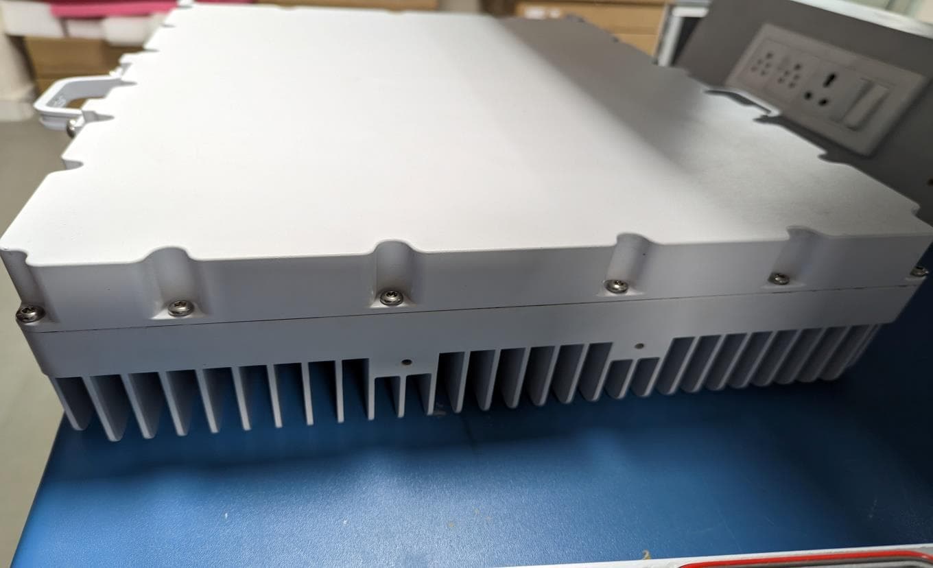
2AWAS-901-00094
May 04, 2023Mavenir Dual-band B25B66 RRU
Equipment Class
TNB - Licensed Non-Broadcast Station Transmitter
2AWAS-MU44UA
Sep 27, 2022Remote Radio Unit
Equipment Class
CBD - Citizens Band Category A and B Devices2AWAS-910-00085
Sep 14, 2021B12 4T4R 160W Radio Unit
Equipment Class
TNB - Licensed Non-Broadcast Station Transmitter
2AWAS-910-00027
Jan 23, 2021Remote Radio Unit
Equipment Class
CBD - Citizens Band Category A and B Devices