2AWCY-P01-007Smart socket
Shenzhen Chaoran Technology Co., Ltd.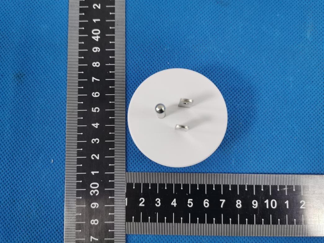
Click to zoom
Application Details
- Equipment Class
- DTS - Digital Transmission System
- Date of Grant
- Jul 07, 2020
- Application Purpose
- Original Equipment
- Date of Application
- Jul 07, 2020
- Equipment Note
- Smart socket
- Frequency Range
- 2412.00000000 - 2462.00000000
- Country
- China
Documents & Files
Document Text
Text extracted from the exhibit documents filed with the FCC. Open a document above to read the original.
Users Manual
Smart Socket User Manual Model:P01-007 Product Schematic // Product Feature 1.Remote control APP (Android&IOS) 2.SupportAmazon Echo, Google Assistant, TmallGenie voice control, IFTTT 3.Timing control,Grouping control 4.0ne - key scene, Automatic scene 5.Device sharing control, family sharing cont「ol -01- Product Parameter Technical Parameters Rated Current: 口10A口16A Rated voltage: AC 110-250V 50/60Hz Wi-Fi Type: 2 .4GHz 802.11 b/g/n Working Temp: -20'C-50'C Support system: Android \10S Turn On Intelligence Use your phone to scan the QR code below or search "Cloud lntellingence" inapplicatlon market to download and install the A pp 黯 Scan to download "Cloud lntellingence" APP -02- "Set light to cool white when rain comes" "Dim the light at 9 PM" "Power on your outlet at sunset." Amazon Echo speaker settings I.Bind device Purchase a device that supports the "Cloud Intelligence" APP binding, add it to the dev -ice list on the homepage, and rename it, such as"My Light". 2. Turn on "Cloud Intelligence" skills (pic7-9) You have to own an Amazon Echo speaker, then search for "Cloud Intelligence" in the Skills of the Alexa app and click "Enable". 3.Linked account(piclO) Enter the account and password of the "Cloud Intelligence" APP to associate "Cloud Intelligence" with "Alexa". 4.Voice control equipment(picll) After association, you can perform voice control on the devices bound to the "Cloud Intelligence" APP, such as: "Alexa, turn on/ off my light." "Alexa, brighten/ dim my light." "Alexa, set my light to yellow." "Alexa, set my light to warm white." 。 � ""w• 心&积沁从 0 ,, 沁 0 """'"必,m, I· 墨刊I" Q ,_,,, 叩记 0 "吓千,,,., 。 女"吓 于 @ -07- -08- > Troubleshooting 1. Cannot connect to Wi-F1 Check if you have selected a 2.4 GHz wifi which is the same that your phone is con -nected with.(lfyour router is dual band, make sure your phone and the smart plug are connected to the 2. 4 G signal.) Check if you have entered the correct Wi Fi password ·Check if there are any internet problems If necessary, reset your Wi-Fi router and try again 2. Cannot control the devices with Alexa/ Google voice control. ·Check if there are any internet problems ·Check if you have enabled"Cloud intellig -ence" in Alexa or Google APP. Check if you are using proper commands when talking to Alexa/Google Assistant, repeat your question, speak clearly to Alexa/ Google Assistant in English Check if you have modified the name of -11- of the plug in "Cloud lntelligence"app. If yes, you need to rediscover the devices through Alexa/ Google app >Notice • Please check if there is damage caused by transportation.If broken, please contact supplier for replacement. • Please follow the instruction and notice to keep product in a good and safe use condition • Do not disassemble or reinstall the bulb. >Customer Service -12-month limited warranty ·Lifetime technical support [email protected] For any inquiries or comments concerning this product, please do not hesitate to contact the seller. We appreciate your support! -12- FCC Caution: Any changes or modifications not expressly approved by the party responsible for compliance could void the user's authority to operate this equipment. This device complies with part 15 of the FCC Rules. Operation is subject to the following two conditions: (1) this device may not cause harmful interference, and (2) this device must accept any interference received, including interference that may cause undesired operation. This device and its antenna(s) must not be co-located or operating in conjunction with any other antenna or transmitter. NOTE: This equipment has been tested and found to comply with the limits for a Class B digital device, pursuant to Part 15 of the FCC Rules. These limits are designed to provide reasonable protection against harmful interference in a residential installation. This equipment generates, uses and can radiate radio frequency energy and, if not installed and used in accordance with the instructions, may cause harmful interference to radio communications. However, there is no guarantee that interference will not occur in a particular installation. If this equipment does cause harmful interference to radio or television reception, which can be determined by turning the equipment off and on, the user is encouraged to try to correct the interference by one or more of the following measures: -- Reorient or relocate the receiving antenna. -- Increase the separation between the equipment and receiver. -- Connect the equipment into an outlet on a circuit different from that to which the receiver is connected. -13- -- Consult the dealer or an experienced radio/TV technician for help. To maintain compliance with FCC’s RF Exposure guidelines, This equipment should be installed and operated with minimum distance between 20cm the radiator your body: Use only the supplied antenna. FCC ID: 2AWCY-P01-007 -15-
External Photos
S19122703913 Model: P01-007 N20191017V1 Photo 1 Photo 2 S19122703913 Model: P01-007 N20191017V1 Photo 3 Photo 4 S19122703913 Model: P01-007 N20191017V1 Photo 5 Photo 6
ID Label/Location Info
131.00mm SMART SOCKET MODEL:P01-007 AC 110-250V / MAX 2200W AC 110-250V /50-60HZ / MAX 10A 2 4GHz 802.11 b/g/n FCC ID:2AWCY-P01-007 氏CE:如吵 SMART SOCKET MODEL: P01-007 AC 110-250V I MAX 2200W AC 110-250V /50-60HZ / MAX 1 OA 2.4GHz 802.11 b/g/n FCC ID.2AWCY-P01-007 冗CE扣吵
Internal Photos
S19122703913 Model: P01-007 N20191017V1 Photo 1 Photo 2 S19122703913 Model: P01-007 N20191017V1 Photo 3 Photo 4 WIFI ANT
Operational Description
version01 Shenzhen Chaoran Technology Co., Ltd. Declaration concerning Antenna Specification It is hereby declared that the product Model No.: P01-007, P01W-007, GJJ-P01W-007, GJJ-P01-007 FCC ID: 2AWCY-P01-007 fulfills the requirement in FCC test relating to the antenna type. The device specified above confirms to the FCC recommendations for internal antenna type(s) described below: Model No. of antenna: N/A Type of antenna:PCB Antenna (1/4 wave antenna) built into the housing) 2.4G WIFI: Gain of the antenna: 1.5 dBi Frequency range: 2412 to 2462 MHz The mounting of the antenna is fixed to the radio module and no other antenna should be used. Company name: Shenzhen Chaoran Technology Co., Ltd. Address:Building 20, Tongfuyu Industrial Zone, Kengzi Longtian, Pingshan New District, City:Shenzhen ZIP / Postal code: Country:China Place:ShenzhenDate: 05/20/2020 Name: Emily mou Signature:
RF Exposure Info
FCC ID: 2AWCY-P01-007 RF EXPOSURE EVALUATION According to FCC 1.1310: The criteria listed in the following table shall be used to evaluate the environment impact of human exposure to radio frequency(RF) Radiation as specified in §1.1307(b) Limits for Maximum Permissible Exposure (MPE) MPE Calculation Method E (V/m) = d GP**30 Power Density: Pd (W/m²) = 377 2 E E = Electric field (V/m) P = Average RF output power (W) G = EUT Antenna numeric gain (numeric) d = Separation distance between radiator and human body (m) The formula can be changed to Pd = 2 *377 **30 D GP From the EUT RF output power, the minimum mobile separation distance, d=0.2m, as well as the gain of the used antenna, the RF power density can be obtained. MAX OUTPUT POWER wifi Condition Mode Frequency (MHz) Antenna Conducted Power (dBm) Limit (dBm) Verdict NVNT 802.11b 2412 Ant 1 12.03 30 Pass NVNT 802.11b 2437 Ant 1 13.61 30 Pass NVNT 802.11b 2462 Ant 1 12.3 30 Pass NVNT 802.11g 2412 Ant 1 7.27 30 Pass NVNT 802.11g 2437 Ant 1 9.05 30 Pass NVNT 802.11g 2462 Ant 1 8.03 30 Pass NVNT 802.11n(HT20) 2412 Ant 1 7.01 30 Pass NVNT 802.11n(HT20) 2437 Ant 1 8.92 30 Pass NVNT 802.11n(HT20) 2462 Ant 1 7.35 30 Pass NVNT 802.11n(HT40) 2422 Ant 1 7.21 30 Pass NVNT 802.11n(HT40) 2437 Ant 1 8.73 30 Pass NVNT 802.11n(HT40) 2452 Ant 1 7.3 30 Pass Measurement Result Operation Frequency: WIFI: 2412-2462MHz for 802.11b/g/11n(HT20); 2422-2452MHz for 802.11(HT40) Power density limited: 1mW/ cm 2 Antenna Type: PCB Antenna Antenna gain: 1.5dBi, R=20cm conducted power Evaluation result Power density Limits (dBm)(mW)(dBi)Numeric 241212.03 13±114 25.1191.501.410.00711 243713.61 13±114 25.1191.501.410.00711 246212.3 13±114 25.1191.501.410.00711 24127.27 8.5±19.5 8.9131.501.410.00251 24379.05 8.5±19.5 8.9131.501.410.00251 24628.03 8.5±19.5 8.9131.501.410.00251 24127.01 8±19 7.9431.501.410.00221 24378.92 8±19 7.9431.501.410.00221 24627.35 8±19 7.9431.501.410.00221 24227.21 8±19 7.9431.501.410.00221 24378.73 8±19 7.9431.501.410.00221 24527.3 8±19 7.9431.501.410.00221 Channel Freq. (MHz) modulation Tune-up power (dBm) (dBm) 802.11g 802.11n(HT 20) 802.11n(H40 ) (mW/cm2 )(mW/cm2) Antenna Gain 802.11b Max tune-up power Conclusion: For the max result : 0.0071≤ 1.0 for Max Power Density, compliance RF exposure.. Signature: Date: 2020-07-03 NAME AND TITLE (Please print or type): Alex Li/Manager COMPANY (Please print or type): Shenzhen NTEK Testing Technology Co., Ltd./ 1/F, Building E, Fenda Science Park, Sanwei Community, Xixiang Street Bao’an District, Shenzhen P.R. China.
Test Report
Report No.:S19122703913001 Version.1.3 Page 1 of 73 FCC RADIO TEST REPORT FCC ID: 2AWCY-P01-007 Product: Smart socket Trade Mark: N/A Model No.: P01-007 Family Model: P01W-007, GJJ-P01W-007, GJJ-P01-007 Report No.: S19122703913001 Issue Date: 10 Jun. 2020 Prepared for Shenzhen Chaoran Technology Co., Ltd. Building 20, Tongfuyu Industrial Zone, Kengzi Longtian, Pingshan New District, Shenzhen, China Prepared by Shenzhen NTEK Testing Technology Co., Ltd. 1/F, Building E, Fenda Science Park Sanwei, Xixiang, Bao'an District Shenzhen, Guangdong, China Tel.: +86-755-6115 6588 Fax.: +86-755-6115 6599 Website:http://www.ntek.org.cn Report No.:S19122703913001 Version.1.3 Page 2 of 73 TABLE OF CONTENTS 1 TEST RESULT CERTIFICATION ...................................................................................................................... 3 2 SUMMARY OF TEST RESULTS ......................................................................................................................... 4 3 FACILITIES AND ACCREDITATIONS ............................................................................................................. 5 3.1 FACILITIES ....................................................................................................................................................... 5 3.2 LABORATORY ACCREDITATIONS AND LISTINGS .................................................................................... 5 3.3 MEASUREMENT UNCERTAINTY ............................................................................................................... 5 4 GENERAL DESCRIPTION OF EUT .................................................................................................................. 6 5 DESCRIPTION OF TEST MODES ..................................................................................................................... 8 6 SETUP OF EQUIPMENT UNDER TEST ......................................................................................................... 10 6.1 BLOCK DIAGRAM CONFIGURATION OF TEST SYSTEM ..................................................................... 10 6.2 SUPPORT EQUIPMENT............................................................................................................................... 11 6.3 EQUIPMENTS LIST FOR ALL TEST ITEMS .............................................................................................. 12 7 TEST REQUIREMENTS .................................................................................................................................... 14 7.1 CONDUCTED EMISSIONS TEST ............................................................................................................... 14 7.2 RADIATED SPURIOUS EMISSION ............................................................................................................ 17 7.3 6DB BANDWIDTH ....................................................................................................................................... 26 7.4 DUTY CYCLE ............................................................................................................................................... 28 7.5 MAXIMUM OUTPUT POWER .................................................................................................................... 29 7.6 POWER SPECTRAL DENSITY ................................................................................................................... 31 7.7 CONDUCTED BAND EDGE MEASUREMENT......................................................................................... 33 7.8 SPURIOUS RF CONDUCTED EMISSIONS................................................................................................ 35 7.9 ANTENNA APPLICATION .......................................................................................................................... 36 8 TEST RESULTS ................................................................................................................................................... 37 8.1 MAXIMUM CONDUCTED OUTPUT POWER ....................................................................................................... 37 8.2 OCCUPIED CHANNEL BANDWIDTH .................................................................................................................. 38 8.3 MAXIMUM POWER SPECTRAL DENSITY LEVEL ............................................................................................... 45 8.4 BAND EDGE .................................................................................................................................................... 52 8.5 CONDUCTED RF SPURIOUS EMISSION ............................................................................................................. 61 Report No.:S19122703913001 Version.1.3 Page 3 of 73 1 TEST RESULT CERTIFICATION Applicant’s name ......................... : Shenzhen Chaoran Technology Co., Ltd. Address ....................................... : Building 20, Tongfuyu Industrial Zone, Kengzi Longtian, Pingshan New District, Shenzhen, China Manufacturer's Name .................. : Shenzhen Chaoran Technology Co., Ltd. Address ....................................... : Building 20, Tongfuyu Industrial Zone, Kengzi Longtian, Pingshan New District, Shenzhen, China Product description Product name .............................. : Smart socket Model and/or type reference ..... : P01-007 Family Model ............................... : P01W-007, GJJ-P01W-007, GJJ-P01-007 Measurement Procedure Used: APPLICABLE STANDARDS APPLICABLE STANDARD/ TEST PROCEDURE TEST RESULT FCC 47 CFR Part 2, Subpart J FCC 47 CFR Part 15, Subpart C ANSI C63.10-2013 KDB 558074 D01 15.247 Meas Guidance v05r02 Complied This device described above has been tested by Shenzhen NTEK Testing Technology Co., Ltd., and the test results show that the equipment under test (EUT) is in compliance with the FCC requirements. And it is applicable only to the …
Text truncated - open the document above for the full version.
Test Setup Photos
FCC ID: 2AWCY-P01-007 Radiated Measurement Photos FCC ID: 2AWCY-P01-007 Conducted Measurement Photo
Contact Information
Applicant
NICO ZHONG(manager)
Test Firm
Shenzhen NTEK Testing Technology Co., Ltd.Alex Li
[email protected]+86-755-6115-9384
Technical Specifications
| # | Rule Parts | Frequency Range | Power Output |
|---|---|---|---|
| 1 | 15C | 2.41 GHz - 2.46 GHz | 23.00 mW |
Other Applications from Shenzhen Chaoran Technology Co., Ltd.
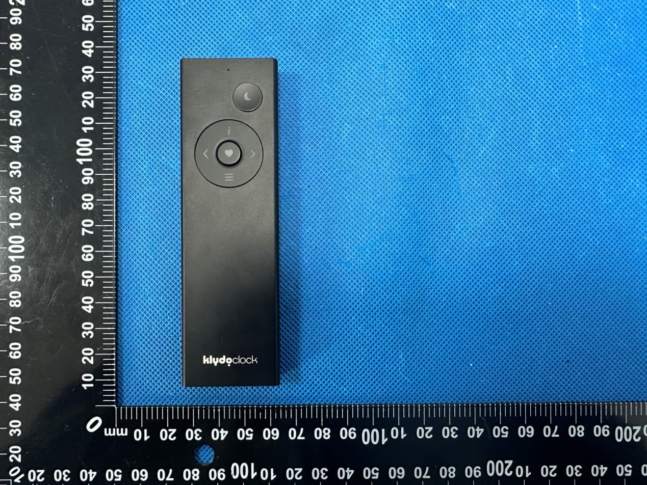
2AWCY-CR12DKL
Dec 11, 2023Remote Control
Equipment Class
DTS - Digital Transmission System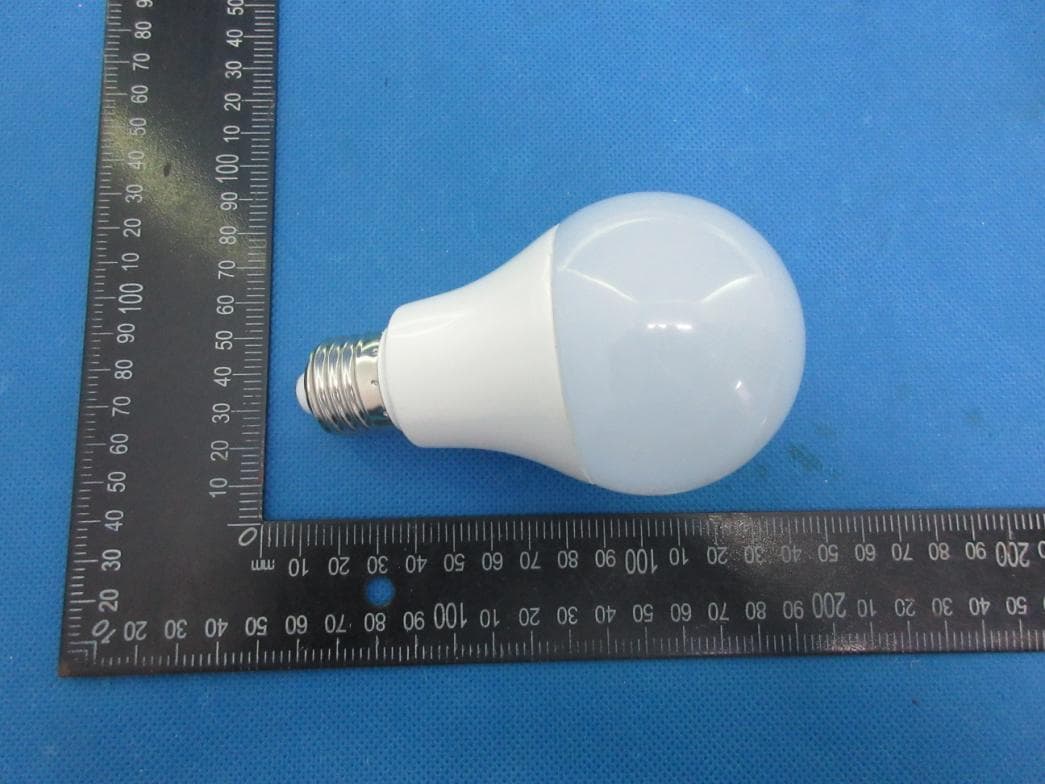
2AWCY-L05
May 21, 2020Smart led bulb
Equipment Class
DTS - Digital Transmission System