2AWE8-WIFI-BOXWIFI-BOX
Ginlong technologies Co.,Ltd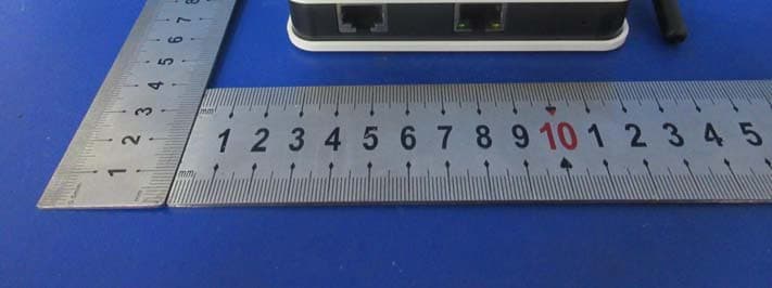
Click to zoom
Application Details
- Equipment Class
- DTS - Digital Transmission System
- Date of Grant
- Oct 11, 2020
- Application Purpose
- Original Equipment
- Date of Application
- Oct 11, 2020
- Equipment Note
- WIFI-BOX
- Frequency Range
- 2412.00000000 - 2462.00000000
- Company
- Ginlong technologies Co.,Ltd
- Country
- China
Documents & Files
Document Text
Text extracted from the exhibit documents filed with the FCC. Open a document above to read the original.
Users Manual
WIFI BOX This device complies with part 15 of the FCC Rules. Operation is subject to the following two conditions: (1) This device may not cause harmful interference, and (2) this device must accept any interference received, including interference that may cause undesired operation. FCC warning: Any Changes or modifications not expressly approved by the party responsible for compliance could void the user's authority to operate the equipment. Note: This equipment has been tested and found to comply with the limits for a Class B digital device, pursuant to part 15 of the FCC Rules. These limits are designed to provide reasonable protection against harmful interference in a residential installation. This equipment generates uses and can radiate radio frequency energy and, if not installed and used in accordance with the instructions, may cause harmful interference to radio communications. However, there is no guarantee that interference will not occur in a particular installation. If this equipment does cause harmful interference to radio or television reception, which can be determined by turning the equipment off and on, the user is encouraged to try to correct the interference by one or more of the following measures: ‐Reorient or relocate the receiving antenna. ‐Increase the separation between the equipment and receiver. ‐Connect the equipment into an outlet on a circuit different from that to which the receiver is connected. ‐Consult the dealer or an experienced radio/TV technician for help. This equipment complies with FCC radiation exposure limits set forth for an uncontrolled environment. This equipment should be installed and operated with minimum distance 20cm between the radiator & your body. IC warning ‐ English: This device complies with Industry Canada licence‐exempt RSS standard(s). Operation is subject to the following two conditions: (1) This device may not cause interference, and (2) This device must accept any interference, including interference that may cause undesired operation of the device. ‐ French: Le présentappareilestconforme aux CNR d'Industrie Canada applicables aux appareils radio exempts de licence. L'exploitationestautorisée aux deux conditions suivantes: (1) l'appareil ne doit pas produire de brouillage, et (2) l'utilisateur de l'appareildoit accepter tout brouillageradioélectriquesubi, mêmesi le brouillageest susceptible d'encompromettre le fonctionnement. FCC ID: 2AWE8‐WIFI‐BOX 1 WIFI BOX Quick Guide Quick Guide WIFI BOX From this page WIFI BOX is an external data logger in the SolarMAN PV monitoring series. By connecting with single or multiple inverters through RS485/422/232 interface, the Kit can collect information of PV systems from inverters. With the integrated WiFi function, the Kit can connect to router and transmit data to the web server, realizing remote monitoring for users. In addition, Ethernet is also available for connection to router,enabling transmission of data. Users can check the runtime status of the device by checking the 4 LEDs on the panel, indicating Power, 485/422, Link and Status respectively. A : Unpack 2 WIFI BOX Quick Guide B : Install data logger C : Connect data logger and inverters D : Connection setting E : Register on SolarMAN Portal F : Log in SolarMAN Portal to manage power station G : Trouble shootings 3 WIFI BOX Quick Guide This Quick Guide is intended to assist users in quick installation and start of WIFI BOX. If any problems, please refer to corresponding chapters of WIFI BOX User Manual for details. A:Unpack I. Checklist After unpacking the box, please make sure all the items are contained as follows: 1 PV data logger (WIFI BOX) 1 power adapter with European or British plug 2 screws 2 expandable rubber hoses 1 Quick Guide II. Interface and connection Notice: Some products may use RS232. 4 WIFI BOX Quick Guide B:Install data logger WIFI BOX can be either wall-mounted or flatwise. Please refer to User Manual for details. C:Connect data logger and inverters Notice: 1. Power supply of inverters must be cut off before connection. Make sure that all connections are completed, then power the data logger and inverters, otherwise personal injury or equipment damage may be caused. 2. Basic version of WIFI BOX with RS485/422 port can be connected to up to 4 inverters at a time. Advanced version may support up to 32 devices; WIFI BOX with RS232 port can be connected to 1 inverter at a time. I. Connection with single inverter Connect inverter and data logger with network cable, and connect data logger and power supply with power adapter. II. Connection with multiple inverters 1. String connect multiple inverters with network cables. 2. Connect the first or last inverter in the string to data logger with network cable. 3. Connect data logger to power supply with power adapter. RS485/422/232 RS485/422/232 5 WIFI BOX Quick Guide Notice:The connectors of the connection cable may differ according to the brands and models of connected inverters. III. Line order of connector to WIFI BOX IV Confirm connection 6 WIFI BOX Quick Guide When connection between inverter and data logger is finished and with the power on for about 5 minutes, please check the 4 LEDs. If POWER, RS485/422 and STATUS are permanently on, the connection should be successful. If any problems, please refer to G. Debug . D:Connection setting The Kit can transfer information via either WiFi or Ethernet, users may choose the appropriate method accordingly. The configuration of the kit may be set via PC or APP Tool for iPhone and smart phones with Android operation system. Please visit App Store or Google Play to get SolarMAN App for free. I. Connection via WiFi Notice: The setting hereinafter is operated with Windows XP for reference only. If other operating systems are used, please follow the corresponding procedures. 1. Prepare a computer or device with WiFi, e.g. tablet PC and smartphone with WiFi function. 2. Obtain an IP address automatically. ○ 1 Open Wireless…
Text truncated - open the document above for the full version.
Attestation Statements
Ginlong technologies Co.,Ltd Date: 2020-10-12 To: Federal Communications Commission 7435 Oakland Mills Road Columbia, MD FCC ID: 2AWE8-WIFI-BOX To Whom It May Concern: This letter is to ascertain that Ginlong technologies Co.,Ltd EUT : WIFI BOX Model Name : SOLIS‐DLB‐W, GL‐DLB‐W, CS‐GL‐WIFI BOX We will apply for FCC SDOC. If you have any question or concerns, pls. contact us. Sincerely, Client’s signature : Client’s name / title : Ruyi Pan/Safety certification manager Contact information / address: Ginlong technologies Co.,Ltd /No.57 Jintong Road, Binhai, (seafront), Industrial Park, Xiangshan Ningbo, Xhejiang 315712 P.R. China
Cover Letter(s)
Rev 11/20/07 (Ginlong technologies Co.,Ltd) Federal Communications Commission Authorization and Evaluation Division Confidentiality Request regarding application for certification of FCC ID: 2AWE8-WIFI-BOX Pursuant to Sections 0.457 and 0.459 of the Commission’s Rules, we hereby request confidential treatment of information accompanying this application as outlined below: Exhibit Type File Name Block Diagram, Schematics, Operational Description Block Diagram .pdf, Schematics .pdf , Operation Description .pdf The above materials contain trade secrets and proprietary information not customarily released to the public. The public disclosure of these materials may be harmful to the applicant and provide unjustified benefits to its competitors. The applicant understands that pursuant to Section 0.457 of the Rules, disclosure of this application and all accompanying documentation will not be made before the date of the Grant for this application. Pursuant to DA04-1705 June 15, 2004 of the Commission’s public notice, we also request temporary confidential treatment of information accompanying this application as outlined below: Short-term confidentiality requested: 180 days Exhibit Type File Name Internal Photos, Test Setup Photos, Manual Internal Photos .pdf, Test Setup Photos .pdf, User Manual .pdf Sincerely, Name: Ruyi Pan Title: Safety certification manager Company: Ginlong technologies Co.,Ltd
Cover Letter(s)
Difference Statement Models SOLIS-DLB-W, GL-DLB-W, CS-GL-WIFI BOX are the same except the model name September 22, 2020 Name: Ruyi Pan Title: Safety certification manager Company: Ginlong technologies Co.,Ltd
Cover Letter(s)
Z:\2020\Ginlong(锦浪)\EN200430015W (ES200430040W)(Solis--DLB-W)\2.Technical Document\Timco\POA.docx Federal Communications Commission Authorization and Evaluation Division 1435 Oakland Mills Road Columbia, MD 21046 Date: September 22, 2020 SUBJECT: FCC Application for FCC ID: 2AWE8-WIFI-BOX To Whom It May Concern: We, the undersigned, hereby authorize Tony Wei at EMTEK(NINGBO) CO., LTD. on our behalf, to apply to the Federal Communications Commission on our equipment. Any and all acts carried out by EMTEK(NINGBO) CO., LTD. on our behalf shall have the same effect as acts of our own. This is to advise that we are in full compliance with the Anti- Drug Abuse Act. We, the applicant, are not subject to a denial of federal benefits pursuant to Section 5301 of the Anti-Drug Act of 1988, 21 USC853a, and no party to the application is subject to a denial of federal benefits pursuant to that section. Regards, Name: Ruyi Pan Title: Safety certification manager Company: Ginlong technologies Co.,Ltd
External Photos
External photos: ---The End---
ID Label/Location Info
FCC ID : 2AWE8-WIFI-BOX
Internal Photos
Internal photos: ---The End--- Antenna
RF Exposure Info
FCC ID: 2AWE8-WIFI-BOX RF EXPOSURE EVALUATION According to FCC 1.1310: The criteria listed in the following table shall be used to evaluate the environment impact of human exposure to radio frequency(RF) Radiation as specified in §1.1307(b) Limits for Maximum Permissible Exposure (MPE) Frequency Range(MHz) Electric Field Strength(V/m) Magnetic Field Strength(A/m) Power Density(mW/cm 2 ) Average Time (A) Limits for Occupational/Control Exposures 300-1500 -- -- F/300 6 1500-100000 -- -- 5 6 (B) Limits for General Population/Uncontrol Exposures 300-1500 -- -- F/1500 6 1500-100000 -- -- 1 30 11.1 Friis transmission formula: Pd= (Pout*G)\ (4*pi*R 2 ) Where Pd= Power density in mW/cm 2 Pout=output power to antenna in mW G= Numeric gain of the antenna relative to isotropic antenna Pi=3.1416 R= distance between observation point and center of the radiator in cm Pd the limit of MPE,1mW/cm 2 . If we know the maximum gain of the antenna and total power input to the antenna, through the calculation, we will know the distance where the MPE limit is reached. mW = 10^( dBm/10) 11.2 Measurement Result Operation Frequency: 2412MHz-2462MHz; Antenna gain: 2.0dBi; R=20cm WIFI Channel Freq. (MHz) modulation Measured power (dBm) Tune-up power (dBm) Max tune-up power (dBm) Antenna Gain Numeric Evaluation result (mW/cm2) Power density Limits (mW/cm2 ) 2412 802.11b 17.18 16 to18 18 1.58 0.019894321 1 2437 16.33 15 to 17 17 1.58 0.015802621 1 2462 16.44 15 to 17 17 1.58 0.015802621 1 2412 802.11g 15.55 14 to 16 16 1.58 0.012552468 1 2437 15.16 14 to 16 16 1.58 0.012552468 1 2462 15.29 14 to 16 16 1.58 0.012552468 1 2412 802.11n20 15.96 14 to 16 16 1.58 0.012552468 1 2437 15.28 14 to 16 16 1.58 0.012552468 1 2462 15.62 14 to 16 16 1.58 0.012552468 1 2422 802.11n40 13.61 12 to 14 14 1.58 0.007920072 1 2437 13.53 12 to 14 14 1.58 0.007920072 1 2452 13.14 12 to 14 14 1.58 0.007920072 1 *** End of Report ***
Test Report
Report No.ES200430040W Page 1 of 49 Ver.1.0 TEST REPORT $二维码$ Product Name : WIFI BOX Model Number : SOLIS-DLB-W, GL-DLB-W, CS-GL-WIFI BOX FCC ID : 2AWE8-WIFI-BOX Prepared for : GINLONG TECHNOLOGIES CO., LTD. Address : No.57 Jintong Road, Binhai, (seafront), Industrial Park, Xiangshan Ningbo, Xhejiang 315712 P.R. China Prepared by : EMTEK (SHENZHEN) CO., LTD. Address : Building69,Majialong Industry Zone,Nanshan District, Shenzhen, Guangdong, China Tel: (0755) 26954280 Fax: (0755) 26954282 Report Number : ES200430040W Date(s) of Tests : May 20, 2020 to August 30, 2020 Date of issue : October 10, 2020 Report No.ES200430040W Page 2 of 49 Ver.1.0 TABLE OF CONTENTS 1 TEST RESULT CERTIFICATION ............................................................................................................. 3 2 EUT TECHNICAL DESCRIPTION ........................................................................................................... 4 3 SUMMARY OF TEST RESULT ................................................................................................................ 5 4 TEST METHODOLOGY ........................................................................................................................... 6 4.1 GENERAL DESCRIPTION OF APPLIED STANDARDS .................................................................. 6 4.2 MEASUREMENT EQUIPMENT USED ............................................................................................ 6 4.3 DESCRIPTION OF TEST MODES ................................................................................................... 7 5 FACILITIES AND ACCREDITATIONS ..................................................................................................... 8 5.1 FACILITIES ...................................................................................................................................... 8 5.2 LABORATORY ACCREDITATIONS AND LISTINGS ....................................................................... 8 6 TEST SYSTEM UNCERTAINTY .............................................................................................................. 9 7 SETUP OF EQUIPMENT UNDER TEST ............................................................................................... 10 7.1 RADIO FREQUENCY TEST SETUP 1 ........................................................................................... 10 7.2 RADIO FREQUENCY TEST SETUP 2 ........................................................................................... 10 7.3 CONDUCTED EMISSION TEST SETUP ........................................................................................ 11 7.4 BLOCK DIAGRAM CONFIGURATION OF TEST SYSTEM ........................................................... 12 7.5 SUPPORT EQUIPMENT ................................................................................................................ 12 8 TEST REQUIREMENTS ......................................................................................................................... 13 8.1 DTS (6DB) BANDWIDTH ............................................................................................................... 13 8.2 MAXIMUM PEAK CONDUCTED OUTPUT POWER ..................................................................... 20 8.3 MAXIMUM POWER SPECTRAL DENSITY ................................................................................... 21 8.4 UNWANTED EMISSIONS IN NON-RESTRICTED FREQUENCY BANDS ................................... 28 8.5 RADIATED SPURIOUS EMISSION ............................................................................................... 33 8.6 CONDUCTED EMISSIONS TEST ................................................................................................. 45 8.7 ANTENNA APPLICATION .............................................................................................................. 48 Report No.ES200430040W Page 3 of 49 Ver.1.0 1 TEST RESULT CERTIFICATION Applicant : GINLONG TECHNOLOGIES CO., LTD. Address : No.57 Jintong Road, Binhai, (seafront), Industrial Park, Xiangshan Ningbo, Xhejiang 315712 P.R. China Manufacturer : GINLONG TECHNOLOGIES CO., LTD. Address : No.57 Jintong Road, Binhai, (seafront), Industrial Park, Xiangshan Ningbo, Xhejiang 315712 P.R. China EUT : WIFI BOX Model Name : SOLIS-DLB-W, GL-DLB-W, CS-GL-WIFI BOX Trademark : Solis Measurement Procedure Used: APPLICABLE STANDARDS STANDARD TEST RESULT FCC 47 CFR Part 2, Subpart J FCC 47 CFR Part 15, Subpart C PASS The above equipment was tested by EMTEK (SHENZHEN) CO., LTD. The test data, data evaluation, test procedures, and equipment configurations shown in this report were made in accordance with the procedures given in ANSI C63.10 (2013) and the energy emitted by the sample EUT tested as described in this report is in compliance with the requirements of FCC Rules Part 2 and Part 15.247 The test results of this report relate only to the tested sample identified in this report. Date of Test : May 20, 2020 to August 30, 2020 Prepared by : SewenGuo /Editor Reviewer : Joe Xia/Editor Approve & Authorized Signer : Lisa Wang/Manager Report No.ES200430040W Page 4 of 49 Ver.1.0 2 EUT TECHNICAL DESCRIPTION Note: for more details, please refer to the User’s manual of the EUT. Characteristics Description Product WIFI BOX Model Number SOLIS-DLB-W, GL-DLB-W, CS-GL-WIFI BOX (Note: All models are the same except the model name, we prepared model SOLIS-DLB-W for EMC test.) IEEE 802.11 WLAN Mode Supported 802.11b 802.11g 802.11n(20MHz channel bandwidth) 802.11n(40MHz channel bandwidth) Data Rate 802.11 b:1,2,5.5,11Mbps; 802.11 g:6,9,12,18,24,36,48,54Mbps; 802.11n(HT20): MCS0~7,up to65Mbps 802.11n(HT40): MCS0~7,up to 150Mbps Modulation DSSS with DBPSK/DQPSK/CCK for 802.11b; OFDM with BPSK/ CCK /16QAM/64QAM for 802.11g/n; Operating Frequency Range 2412-2462MHz for 802.11b/g/n(HT20); 2422-2452MHz for 802.11n(HT40); Number of Channels 11 channels for 802.11b/g n(HT20); 7 Channels…
Text truncated - open the document above for the full version.
Test Setup Photos
Conducted Radiated ---The End---
Contact Information
Applicant
Ruyi Pan(Safety certification manager)
Test Firm
EMTEK (Shenzhen) Co., Ltd.Lisa Wang
[email protected]86 755 26954280
Technical Specifications
| # | Rule Parts | Frequency Range | Power Output |
|---|---|---|---|
| 1 | 15C | 2.41 GHz - 2.46 GHz | 52.20 mW |
Other Applications from Ginlong technologies Co.,Ltd
2AWE8-S6ER1P-H
Aug 13, 2024hybrid inverter
Equipment Class
DTS - Digital Transmission System
2AWE8-S1-W4G
Dec 14, 2022W4G Stick
Equipment Class
PCB - PCS Licensed Transmitter
2AWE8-S4-WIFI
Jul 18, 2022WiFi Stick
Equipment Class
DTS - Digital Transmission System
2AWE8-GPRS-BOX
Mar 02, 2021GPRS BOX
Equipment Class
PCB - PCS Licensed Transmitter