2AWGGWCACWireless Charger
Aira Inc.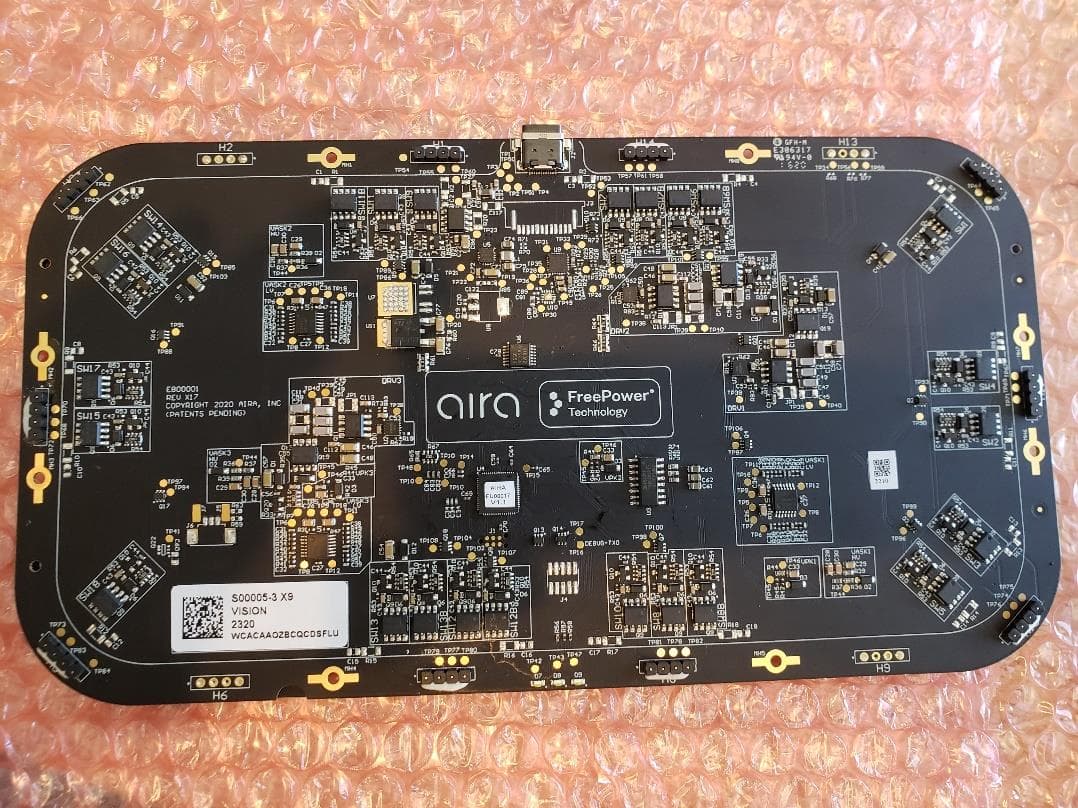
Click to zoom
Application Details
- Equipment Class
- DCD - Part 15 Low Power Transmitter Below 1705 kHz
- Date of Grant
- Jul 06, 2020
- Application Purpose
- Original Equipment
- Date of Application
- Jul 05, 2020
- Equipment Note
- Wireless Charger
- Frequency Range
- 0.11100000 - 0.20000000
- Company
- Aira Inc.
- Country
- United States
Documents & Files
Document Text
Text extracted from the exhibit documents filed with the FCC. Open a document above to read the original.
Users Manual
1 Rev 20200702A Exhibit 8: User Manual Wireless Charging FreePower™ Technology Base 2 Rev 20200702A User Manual Thank you for choosing the Aira FreePower™ Technolgy Wireless Charger. This wireless charging base is optimized to work with iPhone, iPod, iPodPro, Samsung, Google Pixel and other wireless charging technology devices. The product is a wireless charger, which allows up to 3 devices to charge anywhere within the charging surface of the product. Package contents • Aira FreePower™ Technology Charging base • User Manual • AC Adaptor (30W) • USB-C cable • USB-A cable Features • FreePower™ Technology has the freedom to charge the device placed anywhere on the surface • Proprietary Controlling circuitry • Multi-Device Charging simultaneously • High speed charging, up to 7.5W • FOD (Foreign Object Detection) • LED indicator light Charging your wireless device 1. Connect the AC Wall adapter to the FreePower™ Technology base via the USB-C connector, and to the wall outlet. 3 Rev 20200702A 2. Place the device anywhere on the FreePower™ Technology base. In about 1 second the FreePower™ Technology base and device will communicate and begin to charge. 4 Rev 20200702A FCC ID: 2AWGGWCAC FCC § 15.21 Information to user The user’s manual or instruction manual for an intentional or unintentional radiator shall caution the user that changes or modifications not expressly approved by the party responsible for compliance could void the user's authority to operate the equipment. This device complies with Part 15, Subpart B, of the FCC rules. Operation is subject to the following two conditions: (1) this device may not cause harmful interference, and (2) this device must accept any interference received, including interference that may cause undesired operation. This equipment has been tested and found to comply with the limits for a Class B digital device, pursuant to Part 15, Subpart C, of the FCC Rules. These limits are designed to provide reasonable protection against harmful interference when the equipment is operated in a residential environment. This equipment generates, uses, and can radiate radio frequency energy and, if not installed and used in accordance with the instructions, may cause harmful interference to radio communications. However, there is no guarantee that interference will not occur in an installation. If this equipment does cause harmful interference to radio or television reception, which can be determined by tuning the equipment off and on, the user is encouraged to try to correct the interference by one or more of the following measures: • Reorient or relocate the receiving antenna • Increase the separation between the equipment and the receiver • Connect the equipment into an outlet on a circuit different from that to which the receiver is connected • Consult the dealer or an experienced radio/TV technician for help Caution: To comply with the limits for an FCC Part 15 computing device, always use shielded signal cables. 5 Rev 20200702A FCC Radiation Exposure Statement This equipment complies with FCC radiation exposure limits set forth for an uncontrolled environment. This equipment should be installed and operated with a minimum distance of 8 inches (20.3 cm) between the radiator and your body. Specifications • Input :110 - 240VAC, 50/60Hz, 2A • Output: up to 7.5W (Fast Charge) - charging time may vary based on device ⚠DANGER - To reduce the risk of electric shock • Always unplug the device from the electrical outlet • Do not reach for a device that has fallen into water. Unplug it immediately. • Do not place or store devices where it can fall or be pulled into a tub of or sink. • Do not place in or drop into water or other liquid. WARNING ⚠Read all instructions and warnings before using this product. Improper use may result in product damage, excess heat, fire, or explosion, for which you (“Purchaser”), and not Aira Inc. (“Manufacturer”) are responsible. To reduce the risk of burns, fire, electrical shock, or injury to persons: • Use AC Adaptor with UL approved • Do not use with an extension cord • Children should be closely supervised to ensure they do not play with the device • Use this device only for its intended use as described in this manual. Do not use unauthorized accessories of devices. • Never operate this device if it has a damage cord, plug, cable, or housing. If it is not working properly, if it has been dropped or damaged, return it to the dealer for examination or repair. 6 Rev 20200702A • Keep the cord away from heated surfaces. • This device is designed for indoor use only. • Only set on dry surfaces. Do not place on surface wet from water or cleaning solvents. Troubleshooting Guide Description LED Behavior Troubleshooting Powering on Charger 2.5 second off, then all three LED's are on bright, then fade to off, slowly, about 0.5 seconds Normal Operation Device Charging One LED on for each 1/3 of the charging surface. LED on, bright, and about 5 seconds later, dims Normal Operation Device Charge cycle complete LED remains on, dimly lit Normal Operation FOD detected or Charging too warm LED's blink at uniform cadence Check surface for FOD Check under the charger for FOD Remove the device System error/Power Adapter error All 3 LED's blink on 3x, then off 1x Power supply error, too low Wattage Replace with new AC Adapter LED’s for each of the three charging areas. 7 Rev 20200702A Warranty One year limited warranty to the original purchaser only in that this product is free from defects in workmanship and materials from the date of purchase (damages through normal wear and tear, alteration, misuse, neglect, accident, service by anyone other than the authorized service center, act of God not included). During this warranty period, upon verification of defects, this product will be repaired or replaced at the discretion of the manufacturer. This limited warranty is in lieu of all other warranties, express or implied, including, but not limited to implied warra…
Text truncated - open the document above for the full version.
Cover Letter(s)
Page 1 of 1 This document contains proprietary and confidential information that is the sole property of Aira Inc. Distribution of this document in whole or in part to a third party is prohibited without prior written authorization from Aira Inc. - Copyright Aira Inc. 2020 Date 05/06/2020 TUV SUD America Inc. 10 Centennial Drive Peabody, MA 01960, USA Dear Sir or Madam, We, Aira Inc., 6100 W. Gila Springs Place, Chandler, AZ 85226, i.e. applicant hereby authorize Hoosamuddin S. Bandukwala of H.B. Compliance Solutions to act as our agent in all matters relating to applications for equipment authorization, including the signing of all documents relating to these matters. Yours sincerely, Name: Dean Heyl Title: Director of Operations
Cover Letter(s)
Page 1 of 1 This document contains proprietary and confidential information that is the sole property of Aira Inc. Distribution of this document in whole or in part to a third party is prohibited without prior written authorization from Aira Inc. - Copyright Aira Inc. 2020 Date 06/18/2020 Federal Communications Commission Equipment Authorization Branch 7435 Oakland Mills Road Columbia, MD 21046 Confidentiality Request FCC ID: 2AWGGWCAC Pursuant to Sections 0.457(d)(1)(ii) and 0.459 of the Commission’s Rules, Aira Inc. hereby requests permanent confidential treatment of information accompanying this application as outlined below: Schematics Bill of Materials/Parts List Block Diagrams Theory of Operation Aira Inc also hereby requests short-term confidential treatment of information accompanying this application as outlined below for a period of period of 49 days: Internal Photos External Photos User Manual Test Set-up Photographs The above materials contain trade secrets and proprietary information not customarily released to the public. The public disclosure of these matters might be harmful to the Applicant and provide unjustified benefits to its competitors. The Applicant understands that pursuant to Rule 0.457(d)(1)(ii), disclosure of this Application and all accompanying materials will not be made before the date of the Grant for this Application. Yours sincerely, Name: Dean Heyl Title: Director of Operations
External Photos
1 Exhibit 3 External Photos Component Side Coil Side 2 Coil side – H7, H8 side Coil side – H11 3 Coil side – H1, H14 side Component side – H4 end 4 Component side – H11 end Component side – USB C connector 5 Component side – USB C connector Component side – LED’s sides
ID Label/Location Info
Exhibit 1 ID Label/Location Info Label contents: “FCC ID: 2AWGGWCAC This device compiles with Part 15 of the FCC Rules. Operation is subject to the following two conditions: (1) this device may not cause harmful interference, and (2) this device must accept any interference received, including interference that may cause undesired operation.” • Assembly PN – S00005-1 • Unique 5 Digit Manufacturing ID or Logo • Date Code: WWYY • 17 Digit Aira Serial number (Provided by Aira Functional Test Fixture) • Label must provide the above information in both human readable and GS1 Data Matrix formats
Internal Photos
Exhibit 9: Internal photos Below the standard USB-C receptacle, mounted directly on the main PCBA, is shown. Below the flex connector is used to go between the main board and an off-board USB-C receptacle. The electronics within the two PCBAs are identical. The only difference between the two options is the USB-C connector location. The flex connector contains the same pin connections that would be carried within the USB-C cable.
RF Exposure Info
Certificates and reports shall not be reproduced except in full, without the written permission of H.B Compliance Solutions, LLC. RF Exposure Evaluation Report For the Aira Wireless Charger May 19, 2020 Prepared for: Aira 6100 W Gila Springs Place, Suite 25 Chandler, AZ 85226 Prepared By: H.B. Compliance Solutions 5005 S. Ash Avenue, Suite # A-10 Tempe, Arizona 85282 Reviewed By: Hoosamuddin Bandukwala Cert # ATL-0062-E HBCS RF Exposure Report # EMC_20016_1 Page 2 of 8 1. Equipment Overview Product Name: Wireless Charger Model(s) Tested: N/A FCC ID: 2AWGGWCAC Supply Voltage Input: Primary Power: 120VAC Frequency Range: 0.111 – 0.200 MHz No. of Channels: 3 Type(s) of Modulation: Sinewave Range of Operation Power: 0.000050 Watts (Radiated) Emission Designator: N/A Channel Spacing(s) None Test Item: Pre-Production Type of Equipment: Fixed Antenna Requirement (§15.203): Type of Antenna: Integral Loop Gain of Antenna: 0dBi Environmental Test Conditions: Temperature: 15-35⁰C Humidity: 30-60% Barometric Pressure: 860-1060 mbar Modification to the EUT: None Evaluated By: Staff at H.B Compliance Solutions Test Date(s): 05/19/2020 HBCS RF Exposure Report # EMC_20016_1 Page 3 of 8 2. Applicable Standard According to §1.1307 the criteria listed in table 1 shall be used to evaluate the environmental impact of human exposure to radio frequency (RF) radiation as specified in §1.1307(b), except in the case of portable devices which shall be evaluated according to the provisions of §2.1093 of this chapter. RF exposure is calculated according to KDB680106 D01v03: RF Exposure Wireless Charging. 3. Test Limits Evaluated against exposure limits: General Use _X_ or Controlled Use ___ Maximum Permissible Exposure (MPE) f = frequency in MHz* = Plane-wave equivalent power density RF exposure compliance will need to be determined with respect to 1.1307(c) and (d) of the FCC rules. The emissions should be within the limits at 300kHz in the above table. (Use 300kHz limits for 150kHz) HBCS RF Exposure Report # EMC_20016_1 Page 4 of 8 4. RF Exposure Requirements This device and the test results is in compliance with item 5 of FCC KDB 680106 D01v03 below and can be excluded from submitting an RF exposure evaluation 1. Power transfer frequency is less than 1MHz 2. Output power from each primary coil is less than or equal to 15 watts 3. The transfer system includes only single primary and secondary coils. This includes charging systems that may have multiple primary coils and clients that are able to detect and allow coupling only between individual pairs of coils. 4. Client device is placed directly in contact with the transmitter 5. Mobile exposure conditions only (portable exposure conditions are not covered by the exclusion) 6. The aggregate H-field strengths at 15cm surrounding the device and 20cm above the top surface from all simultaneous coils are demonstrated to be less than 50% of the MPE Limit. HBCS RF Exposure Report # EMC_20016_1 Page 5 of 8 5. Test Limits Evaluated against exposure limits: General Use _X_ or Controlled Use ___ Maximum Permissible Exposure (MPE) f = frequency in MHz* = Plane-wave equivalent power density RF exposure compliance will need to be determined with respect to 1.1307(c) and (d) of the FCC rules. The emissions should be within the limits at 300kHz in the above table. (Use 300kHz limits for 150kHz) HBCS RF Exposure Report # EMC_20016_1 Page 6 of 8 6. Measurement Procedure Test Setup 1. The RF exposure test was performed in a Shield Room 2. For RF exposure purposes, the E and H field strengths were measured separately with E and H field probes. 3. EUT was placed on a turntable and the measurement probe was placed at distance of 15cm from the center of the probe to the edge of the device. 4. The measurement probe used to search for the highest strength 5. The highest emission level was recorded and compared with the limit for each point (A, B, C, D & E) 6. The EUT were measured according to the KDB 680106d01v03. HBCS RF Exposure Report # EMC_20016_1 Page 7 of 8 7. Test Results Frequency Range (MHz) Probe Position A (A/m) Probe Position B (A/m) Probe Position C (A/m) Probe Position D (A/m) Probe Position E (A/m) FCC Limits (A/m) 0.128 0.1643 0.251 0.1643 0.2161 0.610 1.63 H-Field Strength at 15cm from the edges surrounding the EUT Frequency Range (MHz) Probe Position A (V/m) Probe Position B (V/m) Probe Position C (V/m) Probe Position D (V/m) Probe Position E (V/m) FCC Limits (V/m) 0.128 0.915 1.088 0.994 0.946 2.745 614 E-Field Strength at 15cm from the edges surrounding the EUT Note: The worst-case data were reported. The field strength limit refers to Part 1.1310 and the test results of exposure is compliant. 50% of the MPE limit (E-Field: 307 V/m; H-field: 0.815A/m) Device meets the RF Exposure limits based on the above measurement. HBCS RF Exposure Report # EMC_20016_1 Page 8 of 8 8. Test Equipment Equipment Manufacturer Model Serial # Last Cal Date Cal Due Date Electric Field Probe ETS Lindgren HI-6105 58758 May-08-20 May-08-21 RF Screen Room Lindgren 18-2/2-0 6500 NCR N/A Magnetic Field Meter Combinova MFM-1000 301 Verified Table – Test Equipment List *Statement of Traceability: Test equipment is maintained and calibrated on a regular basis. All calibrations have been performed by a 17025 accredited test facility, traceable to National Institute of Standards and Technology (NIST) END OF TEST REPORT
Test Report
Certificates and reports shall not be reproduced except in full, without the written permission of H.B Compliance Solutions, LLC. Intentional Radiator Test Report For the Aira Wireless Charger Tested under The FCC Rules contained in Title 47 of the CFR, Part 15.209 Prepared for: Aira 6100 W Gila Spring Place, Suite 25 Chandler, AZ 85226 Prepared By: H.B. Compliance Solutions 5005 S. Ash Avenue, Suite # A-10 Tempe, Arizona 85282 Reviewed By: Hoosamuddin Bandukwala Cert # ATL-0062-E Engineering Statement: The measurements shown in this report were made in accordance with the procedure indicated, and the emissions from this equipment were found to be within the limits applicable. I assume full responsibility for the accuracy and completeness of these measurements, and for the qualifications of all persons taking them. It is further stated that upon the basis of the measurement made, the equipment tested is capable of operation in accordance with the requirements of Part 15 of the FCC Rules under normal use and maintenance. All results contained herein relate only to the sample tested. HBCS Report # EMC_20016 Rev1 Page 2 of 24 Report Status Sheet Revision # Report Date Reason for Revision Ø May 16, 2020 Initial Issue 1 July 1, 2020 TCB Comments HBCS Report # EMC_20016 Rev1 Page 3 of 24 Table of Contents EXECUTIVE SUMMARY ............................................................................................ 4 1. Testing Summary ........................................................................................ 4 EQUIPMENT CONFIGURATION ................................................................................ 5 1. Overview .................................................................................................... 5 2. Test Facility ................................................................................................. 6 3. Description of Test Sample ......................................................................... 7 4. Equipment Configuration ........................................................................... 7 5. Support Equipment .................................................................................... 7 6. Ports and Cabling Information .................................................................... 7 7. Method of Monitoring EUT Operation ........................................................ 8 8. Mode of Operation ..................................................................................... 8 9. Modifications ............................................................................................. 8 10. Disposition of EUT ...................................................................................... 8 Criteria for Un-Intentional Radiators ...................................................................... 9 1. Radiated Emissions ..................................................................................... 9 Emissions Tests Calculations ...................................................................... 10 Criteria for Intentional Radiators .......................................................................... 13 2. Conducted Emissions ................................................................................ 13 2. Occupied Bandwidth ................................................................................ 19 5. Radiated Spurious Emissions .................................................................... 21 6. Measurement Uncertainty ............................................................................ 24 HBCS Report # EMC_20016 Rev1 Page 4 of 24 EXECUTIVE SUMMARY 1. Testing Summary These tests were conducted on a sample of the equipment for the purpose of demonstrating compliance with Part 15.209. All tests were conducted using measurement procedure from ANSI C63.4-2014, American National Standard for Methods of Measurement of Radio-Noise Emissions from Low-Voltage Electrical and Electronic Equipment in the range of 9kHz to 40GHz and ANSI C63.10-2013 Procedures for Compliance Testing of Unlicensed Wireless Devices as appropriate. Test Name Test Method/Standard Result Comments Unintentional Radiated Emissions 15.109 Pass A/C Power Line Conducted Emissions 15.207(a) Pass Occupied Bandwidth 15.215 Pass Radiated Fundamental Emissions 15.209(a) Pass Radiated Spurious Emissions 15.209(a), 15.205, 15.35(C) Pass HBCS Report # EMC_20016 Rev1 Page 5 of 24 EQUIPMENT CONFIGURATION 1. Overview H.B Compliance Solutions was contracted by Aira to perform testing on the Wireless charger under the purchase order number 00012. This document describes the test setups, test methods, required test equipment, and the test limit criteria used to perform compliance testing of the Aira, Wireless Charger. The tests were based on FCC Part 15 Rules. The tests described in this document were formal tests as described with the objective of the testing was to evaluate compliance of the Equipment Under Test (EUT) to the requirements of the aforementioned specifications. Aira should retain a copy of this document and it should be kept on file for at least five years after the manufacturing of the EUT has been permanently discontinued. The results obtained relate only to the item(s) tested. Product Name: Wireless Charger Model(s) Tested: N/A FCC ID: 2AWGGWCAC Supply Voltage Input: Primary Power: 120VAC Frequency Range: 111kHz – 200kHz No. of Channels: 3 Type(s) of Modulation: Sinewave Range of Operation Power: 0.000050 Watts (Radiated) Emission Designator: N/A Channel Spacing(s) None Test Item: Pre-Production Type of Equipment: Fixed Antenna Requirement (§15.203): Type of Antenna: Integral Loop Gain of Antenna: 0dBi Environmental Test Conditions: Temperature: 15-35⁰C Humidity: 30-60% Barometric Pressure: 860-1060 mbar Modification to the EUT: None Evaluated By: Staff at H.B Compliance Solutions Test Date(s): 04/21/2020 till 05/18/2020 Firmware Number 0.7.1 PCBA Version X11 HBCS Report # EMC_2001…
Text truncated - open the document above for the full version.
Test Setup Photos
1 | P a g e Test Setup Photos Aira – Project 20016 Test Setup Photo # 1 Test Setup Photo # 2 2 | P a g e Test Setup Photo # 3 Test Setup Photo # 4 3 | P a g e Test Setup Photo # 5 Test Setup Photo # 6 4 | P a g e Test Setup Photo # 7
Contact Information
Applicant
James SCOTT
Test Firm
H.B. Compliance SolutionsHoosamuddin Bandukwala
[email protected]480-684-2969
Technical Specifications
| # | Rule Parts | Frequency Range | Power Output |
|---|---|---|---|
| 1 | 15C | 0.111 MHz - 0.2 MHz | - |
Other Applications from Aira Inc.

2AWGG-CT-T09
Apr 02, 2024Under Countertop Wireless Charger
Equipment Class
DCD - Part 15 Low Power Transmitter Below 1705 kHz
2AWGG-WH1257500
Dec 22, 2022Tesla Wireless Charger
Equipment Class
DCD - Part 15 Low Power Transmitter Below 1705 kHz