2AWPD-BPK7000Bodypack Transmitter for Wireless Microphone System
Kingdom Inc.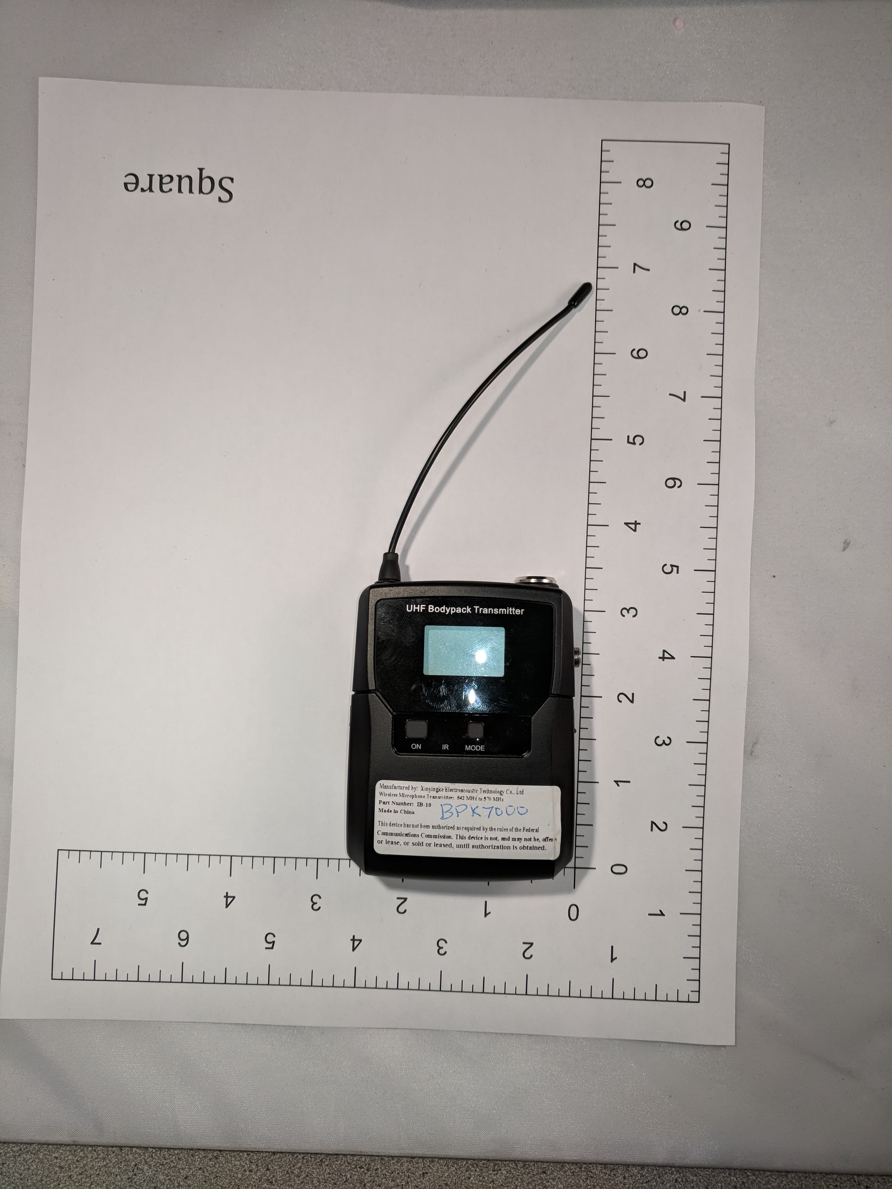
Click to zoom
Application Details
- Equipment Class
- DWM - Part 15 Wireless Microphone
- Date of Grant
- Dec 04, 2025
- Application Purpose
- Original Equipment
- Equipment Note
- Bodypack Transmitter for Wireless Microphone System
- Frequency Range
- 542.00000000 - 548.00000000
- Company
- Kingdom Inc.
- Country
- United States
Documents & Files
Document Text
Text extracted from the exhibit documents filed with the FCC. Open a document above to read the original.
Users Manual
Professional True Diversity Frequency Agile UHF Wireless Microphone System Profesional UHF Sistema de Micrófono Inalámbrico Please read and keep for future reference. For V7000 Series Channel Variants: (4 Mic Systems, 2 Mic Systems, and 1 Mic Systems) 719 Lambs Creek Road Mansfield, PA 16933 U.S.A. 1-800-788-1122 www.kingdom.com Product: Made in China Manual: Printed in China Kingdom V7000 Series Instruction Manual FCC INFORMATION Kingdom ® Inc. 2 RECEIVERS: K7000R1, K7000R2 AND K7000R4 THIS DEVICE COMPLIES WITH PART 15 OF THE FCC RULES. OPERATION IS SUBJECT TO THE FOLLOW- ING TWO CONDITIONS: (1) THIS DEVICE MAY NOT CAUSE HARMFUL INTERFERENCE, AND (2) THIS DEVICE MUST ACCEPT ANY INTERFERENCE RECEIVED, INCLUDING INTERFERENCE THAT MAY CAUSE UNDESIRED OPERATION. TRANSMITTERS: * * * CONSUMER ALERT * * * Most users do not need a license to operate this wireless microphone system. Nev- ertheless, operating this microphone system without a license is subject to certain restrictions: the system may not cause harmful interference; it must operate at a low power level (not in excess of 50 milliwatts); and it has no protection from interference received from any other device. Purchasers should also be aware that the FCC is currently evaluating use of wireless microphone systems, and these rules are subject to change. For more Information, call the FCC at 1-888-CALL-FCC (TTY: 1-888-TELL-FCC) or visit the FCC's wireless microphone website at www.fcc.gov/cgb/wirelessmicrophones. NOTE: The manufacturer, distributor, and supplier is not responsible for any radio or TV interference caused by unauthorized modifications to this equipment. Such modifi- cations could void the user's authority to operate the equipment. K7000R1 (or) K7000R2 (or) K7000R4 Handheld Bodypack/Beltpack Part #: HHK7000 Part #: BPK7000 FCC ID: 2AWPD-HHK7000 FCC ID: 2AWPD-BPK7000 FCC Information ................................... 2 Features and Specifications................ 3 Getting Started .................................. 4-5 Receiver Helpful Diagrams ...............6-8 Transmitter Diagrams........................... 9 IR Sync...........................................10-11 Frequency Group Settings.............12-14 Frequency Channel Setting ............... 15 INDEX EQ Setting...........................................16 -17 Frequency Search.............................. 18-19 Color Setting ........................................... 20 Receiver Auto Lock Setting................21-22 Transmitter Screen & Power Setting....... 23 Troubleshooting.................................. 24-25 Notes .................................................. 26-27 FEATURES & SPECIFICATIONS WARNINGS CAUTION! WARNING! Risk of harmful electric shock! Do not open the device! Opening may result in serious injury! Advertencia: Riesgo de un choque eléctrico. No Abra el aparato. El abrirlo puede causar serias heridas. Do not dispose of this device by putting in the trash. Opening the device may void your warranty. 3 Specifications Frequency Response: 60Hz~20KHz possible with beltpack. Actual will depend on mic attached. The lapel mic induded has a reported frequency response of 60Hz~20KHz. Working Distance: Up to 160 feet Transmitter Power: Approximately 7mW radiated Display: LCD Beltpack Jack: 3.5mm / 1/8 inch lockable jack and 3-pin mini XLR Features Lapel mic included Requires 2 AA batteries (not included) IR sync capable Handheld Transmitter (HHK7000) Bodypack / Beltpack Transmitter (BPK7000) Receiver (K7000R1, K7000R2 or K7000R4) Specifications Frequency Response: 60Hz~20KHz Working Distance: Up to 160 feet Transmitter Power: Approximately 7mW radiated Display: LCD Features Requires 2 AA batteries (not included) IR sync capable Specifications Carrier Wave Frequency Range: UHF 542–548MHz and 554–570MHz Display: TFT LCD External Wall Wart Power Supply Output Connectors: Balanced XLR and Unbalanced 1/4 inch (TRS 6.35mm) Features IR sync capable Frequency selection mode Volume control Auto scan Group select Congratulations on Purchasing a Kingdom ® Wireless Microphone System! This wireless system is a true diversity frequency agile system which can aid in reduced interference. We hope that you will have trouble free performance and complete satisfaction. GETTING STARTED Put 2 batteries into each of your transmitters. The handheld takes 2 AA batteries and the battery compartment can be located by unscrewing the bottom of the handle. The belt- pack takes 2 AA batteries and the compart- ment can be located by swinging open the door. See diagrams on page 9. Attach the two antennae to the back of your receiver. Attach by screwing onto the receiver in the proper location. See picture of your receiver on pages 6, 7 or 8 for help with locat- ing the proper location. Connect your sound system to your wireless microphone system using either 1/4" or XLR cables but not both at the same time. You will need to attach 1 XLR cable for each transmit- ter that you will be operating. For all receivers, when opting to use a 1/4" cable (instead of XLR cables) then only one 1/4" cable needs to be used per receiver regardless of how many transmitters you are operating with that receiver. Generally a cleaner more clear sound can be attained by using XLR cables. We highly rec- ommend the use of XLR cables instead of a 1/4" cable with your system. Plug the wall wart power supply into the back of your receiver and then into an electrical out- let. Power on your receiver using the power switch. Power on your transmitter. Handheld: Push the button in the center of the handheld mic to power it on. Beltpack: Power on using the button located on the center left of the front of the beltpack. Push power button for 3 seconds. See dia- gram on page 9. Now you must sync your transmitter and receiver to the same frequency or channel. By using the receiver controller on your receiver you can toggle through the various receiver settings and choose the IR sync mode. The receivers allow you to acc…
Text truncated - open the document above for the full version.
Test Setup Photos
ANNEX B – Test Setup Photograph Exhibit KINGDOM INC, Model: BPK7000 Conducted Test Setup Radiated Testing, Table Setup #1 Radiated Testing, Above 1 GHz #1 Frequency Stability Testing
Test Setup Photos
ANNEX B – Test Setup Photograph Exhibit KINGDOM INC, Model: BPK7000 SAR Testing- Front SAR Testing External - Front SAR Testing- Back SAR Testing External - Back
Test Report
1) Photo 2) Drawings of the Antenna 3) Gain/Pattern
Test Report
Test Report# TR_18891-25_Bodypack_FCC 15.236_ Revision: 3 Test Report – FCC Part 15.236 Low Power Licensed Wireless Microphone Applicant: KINGDOM INC, Signature: Name & Title: Tim Royer, EMC Engineer Date of Signature 3/13/2025 Signature: Name & Title: Kristoffer Costa, EMC Technician Date of Signature 3/13/2025 This test report relates only to the items tested as identified and is not valid for any subsequent changes or modifications made to the equipment under test. 13146 NW 86 th Drive, Suite 400, Alachua, Florida 32615 (352) 472-5500 / [email protected] Page 2 of 39 This test report shall not be reproduced except in full without the written and signed permission of Timco Engineering Inc., a subsidiary of Industrial Inspection & Analysis, Inc. (IIA). Table of Contents 1. APPLICANT INFORMATION .................................................................................................................................................................. 4 1.1 TEST RESULT SUMMARY ............................................................................................................................................................................................4 2. LOCATION OF TESTING ........................................................................................................................................................................ 5 2.1 TEST LABORATORY .................................................................................................................................................................................................... 5 3. TEST SAMPLE(S) (EUT/DUT) .................................................................................................................................................................. 5 3.1 DESCRIPTION OF THE EUT ........................................................................................................................................................................................ 6 3.2 CONFIGURATION OF EUT ......................................................................................................................................................................................... 7 3.3 TEST SETUP OF EUT .................................................................................................................................................................................................. 7 4. TEST METHODS & APPLICABLE REGULATORY LIMITS ..................................................................................................................... 8 4.1 TEST METHODS/STANDARDS/GUIDANCE ................................................................................................................................................................ 8 5. MEASUREMENT UNCERTAINTY ........................................................................................................................................................... 8 6. ENVIRONMENTAL CONDITIONS ......................................................................................................................................................... 8 7. LIST OF TEST EQUIPMENT AND TEST FACILITY ................................................................................................................................ 9 8. TEST RESULTS ........................................................................................................................................................................................ 10 8.1 RF POWER OUTPUT ............................................................................................................................................................................................ 11 8.1.1 Power Output Plot, 542 MHz .............................................................................................................................................................. 12 8.1.2 Power Output Plot, 554 MHz .............................................................................................................................................................. 13 8.1.3 Power Output Plot, 560 MHz .............................................................................................................................................................. 14 8.1.4 Power Output Plot, 570 MHz .............................................................................................................................................................. 15 8.2 OCCUPIED BANDWIDTH.................................................................................................................................................................................. 16 8.2.1 99% Bandwidth Plot, 542 MHz ........................................................................................................................................................... 17 8.2.2 99% Bandwidth Plot, 554 MHz ........................................................................................................................................................... 18 8.2.3 99% Bandwidth Plot, 560 MHz .......................................................................................................................................................... 19 8.2.4 99% Bandwidth Plot, 570 MHz.......................................................................................................................................................... 20 8.2.5 26dB Bandwidth Plot, 542 MHz .......................................................................................................................................................... 21 8.2.6 26dB Bandwidth Plot, 554 MHz .......................................................................................................................................................... 22 8.2.7 26dB Bandwidth Plot, 560 MHz ......................................................…
Text truncated - open the document above for the full version.
RF Exposure Info
Scans Setup Area ScanZoom Scan Grid Extents [mm]40.0 x 90.030.0 x 30.0 x 30.0 Grid Steps [mm]10.0 x 15.06.0 x 6.0 x 1.5 Sensor Surface [mm]3.01.4 Graded GridN/AYes Grading RatioN/A1.5 MAIAN/AN/A Surface DetectionVMS + 6pVMS + 6p Scan MethodMeasuredMeasured Measurement Results Area ScanZoom Scan Date2025-03-20, 13:562025-03-20, 14:02 psSAR1g [W/Kg]0.0990.10 psSAR10g [W/Kg]0.0690.066 Power Drift [dB]-0.050.00 Power ScalingDisabledDisabled Scaling Factor [dB] TSL CorrectionNo correctionNo correction M2/M1 [%]82.7 Dist 3dB Peak [mm]> 15.0 Measurement Report for Handheld microphone, , , CW, Channel 0 (450.000 MHz) Device Under Test Properties- System Performance Check Model, ManufacturerDimensions [mm]IMEIDUT Type Handheld microphone, KingdomN/A x N/A x N/APhone Exposure Conditions Phantom Section, TSLPosition, Test Distance [mm]BandGroup, UIDFrequency [MHz], Channel NumberConversion FactorTSL Conductivity [S/m]TSL Permittivity Flat, HSL,CW, 0--450.000, 010.720.85144.7 Hardware Setup PhantomTSL, Measured DateProbe, Calibration DateDAE, Calibration Date Twin-SAM V8.0 (30deg probe tilt) - 2186HSL450 Charge: xxxx, 2025-Mar-20EX3DV4 - SN7871, 2024-04-24DAE4ip Sn1859, 2024-03-26 Plot 1 Scans Setup Area ScanZoom Scan Grid Extents [mm]120.0 x 240.030.0 x 30.0 x 30.0 Grid Steps [mm]15.0 x 15.06.0 x 6.0 x 1.5 Sensor Surface [mm]3.01.4 Graded GridN/AYes Grading RatioN/A1.5 MAIAN/AN/A Surface DetectionVMS + 6pVMS + 6p Scan MethodMeasuredMeasured Measurement Results Area ScanZoom Scan Date2025-03-21, 12:312025-03-21, 12:37 psSAR1g [W/Kg]0.4130.427 psSAR10g [W/Kg]0.2790.261 Power Drift [dB]0.01-0.00 Power ScalingDisabledDisabled Scaling Factor [dB] TSL CorrectionNo correctionNo correction M2/M1 [%]77.3 Dist 3dB Peak [mm]12.8 Measurement Report for Bodypack, FRONT, Custom Band, CW, Channel 542000 (542.000 MHz) Device Under Test Properties Model, ManufacturerDimensions [mm]IMEIDUT Type Bodypack, Kingdom192.0 x 62.0 x 25.0Phone Exposure Conditions Phantom Section, TSLPosition, Test Distance [mm]BandGroup, UIDFrequency [MHz], Channel NumberConversion FactorTSL Conductivity [S/m]TSL Permittivity Flat, HSLFRONT, 0.00Custom BandCW, 0--542.000, 54200010.720.92743.2 Hardware Setup PhantomTSL, Measured DateProbe, Calibration DateDAE, Calibration Date Twin-SAM V8.0 (30deg probe tilt) - 2186HSL450 Charge: xxxx, 2025-Mar-20EX3DV4 - SN7871, 2024-04-24DAE4ip Sn1859, 2024-03-26 Plot 2 Scans Setup Area ScanZoom Scan Grid Extents [mm]120.0 x 240.030.0 x 30.0 x 30.0 Grid Steps [mm]15.0 x 15.04.2 x 4.2 x 1.4 Sensor Surface [mm]3.01.4 Graded GridN/AYes Grading RatioN/A1.4 MAIAN/AN/A Surface DetectionVMS + 6pVMS + 6p Scan MethodMeasuredMeasured Measurement Results Area ScanZoom Scan Date2025-03-21, 12:452025-03-21, 12:58 psSAR1g [W/Kg]0.5490.575 psSAR10g [W/Kg]0.3290.280 Power Drift [dB]0.040.03 Power ScalingDisabledDisabled Scaling Factor [dB] TSL CorrectionNo correctionNo correction M2/M1 [%]58.0 Dist 3dB Peak [mm]4.9 Measurement Report for Bodypack, FRONT, Custom Band, CW, Channel 546000 (546.000 MHz) Device Under Test Properties Model, ManufacturerDimensions [mm]IMEIDUT Type Bodypack, Kingdom192.0 x 62.0 x 25.0Phone Exposure Conditions Phantom Section, TSLPosition, Test Distance [mm]BandGroup, UIDFrequency [MHz], Channel NumberConversion FactorTSL Conductivity [S/m]TSL Permittivity Flat, HSLFRONT, 0.00Custom BandCW, 0--546.000, 54600010.720.93043.2 Hardware Setup PhantomTSL, Measured DateProbe, Calibration DateDAE, Calibration Date Twin-SAM V8.0 (30deg probe tilt) - 2186HSL450 Charge: xxxx, 2025-Mar-20EX3DV4 - SN7871, 2024-04-24DAE4ip Sn1859, 2024-03-26 Plot 3 Scans Setup Area ScanZoom Scan Grid Extents [mm]120.0 x 240.030.0 x 30.0 x 30.0 Grid Steps [mm]15.0 x 15.06.0 x 6.0 x 1.5 Sensor Surface [mm]3.01.4 Graded GridN/AYes Grading RatioN/A1.5 MAIAN/AN/A Surface DetectionVMS + 6pVMS + 6p Scan MethodMeasuredMeasured Measurement Results Area ScanZoom Scan Date2025-03-21, 12:132025-03-21, 12:23 psSAR1g [W/Kg]0.4100.425 psSAR10g [W/Kg]0.2770.261 Power Drift [dB]-0.01-0.02 Power ScalingDisabledDisabled Scaling Factor [dB] TSL CorrectionNo correctionNo correction M2/M1 [%]77.4 Dist 3dB Peak [mm]12.4 Measurement Report for Bodypack, FRONT, D600V3, CW, Channel 0 (550.000 MHz) Device Under Test Properties Model, ManufacturerDimensions [mm]IMEIDUT Type Bodypack, Kingdom192.0 x 62.0 x 25.0Phone Exposure Conditions Phantom Section, TSLPosition, Test Distance [mm]BandGroup, UIDFrequency [MHz], Channel NumberConversion FactorTSL Conductivity [S/m]TSL Permittivity Flat, HSLFRONT, 0.00D600V3CW, 0--550.000, 010.720.93443.1 Hardware Setup PhantomTSL, Measured DateProbe, Calibration DateDAE, Calibration Date Twin-SAM V8.0 (30deg probe tilt) - 2186HSL450 Charge: xxxx, 2025-Mar-20EX3DV4 - SN7871, 2024-04-24DAE4ip Sn1859, 2024-03-26 Plot 4 Scans Setup Area ScanZoom Scan Grid Extents [mm]120.0 x 240.030.0 x 30.0 x 30.0 Grid Steps [mm]15.0 x 15.06.0 x 6.0 x 1.5 Sensor Surface [mm]3.01.4 Graded GridN/AYes Grading RatioN/A1.5 MAIAN/AN/A Surface DetectionVMS + 6pVMS + 6p Scan MethodMeasuredMeasured Measurement Results Area ScanZoom Scan Date2025-03-21, 13:212025-03-21, 13:27 psSAR1g [W/Kg]0.100.101 psSAR10g [W/Kg]0.0690.065 Power Drift [dB]0.01-0.02 Power ScalingDisabledDisabled Scaling Factor [dB] TSL CorrectionNo correctionNo correction M2/M1 [%]82.5 Dist 3dB Peak [mm]19.0 Measurement Report for Bodypack, BACK, Custom Band, CW, Channel 542000 (542.000 MHz) Device Under Test Properties Model, ManufacturerDimensions [mm]IMEIDUT Type Bodypack, Kingdom192.0 x 62.0 x 25.0Phone Exposure Conditions Phantom Section, TSLPosition, Test Distance [mm]BandGroup, UIDFrequency [MHz], Channel NumberConversion FactorTSL Conductivity [S/m]TSL Permittivity Flat, HSLBACK, 0.00Custom BandCW, 0--542.000, 54200010.720.92743.2 Hardware Setup PhantomTSL, Measured DateProbe, Calibration DateDAE, Calibration Date Twin-SAM V8.0 (30deg probe tilt) - 2186HSL450 Charge: xxxx, 2025-Mar-20EX3DV4 - SN7871, 2024-04-24DAE4ip Sn1859, 2024-03-26 Plot 5 Scans Setup Area ScanZoom Scan Gr…
Text truncated - open the document above for the full version.
RF Exposure Info
EX3DV4 - SN:7871 IEEE 802.1 lax (20 MHz, MCS5, 99pc duty cycle) IEEE 802.1 lax (20 MHz, MCS10, 99pc duty cycle) April 24, 2024 PAR (dB) Unc k UID 10687 10688 10689 10690 10691 10692 10693 10694 10695 10696 10697 10698 10699 10700 10701 10702 10703 10704 10705 10706 10707 10708 10709 10710 10711 10712 10713 10714 10715 10716 10717 10718 10719 10720 10721 10722 10723 10724 10725 10726 10727 10728 10729 10730 10731 10732 10733 10734 10735 10736 10737 10738 10739 10740 10741 10742 10743 10744 10745 10746 10747 10748 10749 10750 10751 10752 Rev AAC AAC AAC AAC AAC AAC AAC AAC AAC AAC AAC AAC AAC AAC AAC AAC AAC AAC AAC AAC AAC AAC AAC AAC AAC AAC AAC AAC AAC AAC AAC AAC AAC AAC AAC AAC AAC AAC AAC AAC AAC AAC AAC AAC AAC AAC AAC AAC AAC AAC AAC AAC AAC AAC AAC AAC AAC AAC AAC AAC AAC AAC AAC AAC AAC AAC Communication System Name IEEE 802.1 lax (20 MHz, MCS4, 99pc duty cycle) IEEE 802.1lax (20 MHz, MCS6, 99pc duty cycle) IEEE 802.1 lax (20 MHz, MCS7, 99pc duty cycle) IEEE 802.1 lax (20 MHz, MCS8, 99pc duty cycle) IEEE 802.1 lax (20 MHz, MCS9, 99pc duty cycle) IEEE 802.1 lax (20 MHz, MCSI 1, 99pc duty cycle) IEEE 802.1 lax (40 MHz, MCSO, 90pc duty cycle) IEEE 802.1 lax (40 MHz, MCSI, 90pc duty cycle) IEEE 802.1 lax (40 MHz, MCS2, 90pc duty cycle) IEEE 802.1 lax (40 MHz, MCS3, 90pc duty cycle) IEEE 802.1 lax (40 MHz, MCS4, 90pc duty cycle) IEEE 802.1 lax (40 MHz, MCS5, 90pc duty cycle) IEEE 802.1lax (40 MHz, MCS6, 90pc duty cycle) IEEE 802.1 lax (40 MHz, MCS7, 90pc duty cycle) IEEE 802.1 lax (40 MHz, MCS8, 90pc duty cycle) IEEE 802.1 lax (40 MHz, MCS9, 90pc duty cycle) IEEE 802.1 lax (40 MHz, MCSIO, 90pc duty cycle) IEEE 802.1 lax (40 MHz, MCSI 1, 90pc duty cycle) IEEE 802.1 lax (40 MHz, MCSO, 99pc duty cycle) IEEE 802.1 lax (40 MHz, MCSI , 99pc duty cycle) IEEE 802.1 lax (40 MHz, MCS2, 99pc duty cycle) IEEE 802.1 lax (40 MHz, MCS3, 99pc duty cycle) IEEE 802.1 lax (40 MHz, MCS4, 99pc duty cycle) IEEE 802.1 lax (40 MHz, MCS5, 99pc duty cycle) IEEE 802.1 lax (40 MHz, MCS6, 99pc duty cycle) IEEE 802.1 lax (40 MHz, MCS7, 99pc duty cycle) IEEE 802.1 lax (40 MHz, MCS8, 99pc duty cycle) IEEE 802.1 lax (40 MHz, MCS9, 99pc duty cycle) IEEE 802.1 lax (40 MHz, MCSIO, 99pc duty cycle) IEEE 802.1 lax (40 MHz, MCSI I, 99pc duty cycle) IEEE 802.1 lax (80 MHz, MCSO, 90pc duty cycle) IEEE 802.1 lax (80 MHz, MCSI, 90pc duty cycle) IEEE 802.1 lax (80 MHz, MCS2, 90pc duty cycle) IEEE 802.1 lax (80 MHz, MCS3, 90pc duty cycle) IEEE 802.1 lax (80 MHz, MCS4, 90pc duty cycle) IEEE 802.1 lax (80 MHz, MCS5, 90pc duty cycle) IEEE 802.1 lax (80 MHz, MCS6, 90pc duty cycle) IEEE 802.1 lax (80 MHz, MCS7, 90pc duty cycle) IEEE 802.1 lax (80 MHz, MCS8, 90pc duty cycle) IEEE 802.1 lax (80 MHz, MCS9, 90pc duty cycle) IEEE 802.1 lax (80 MHz, MCSIO, 90pc duty cycle) IEEE 802.1 lax (80 MHz, MCSI 1 , 90pc duty cycle) IEEE 802.1 lax (80 MHz, MCSO, 99pc duty cycle) IEEE 802.1 lax (80 MHz, MCSI , 99pc duty cycle) IEEE 802.1 lax (80 MHz, MCS2, 99pc duty cycle) IEEE 802.1 lax (80 MHz, MCS3, 99pc duty cycle) IEEE 802.1 lax (80 MHz, MCS4, 99pc duty cycle) IEEE 802.1 lax (80 MHz, MCS5, 99pc duty cycle) IEEE 802.1 lax (80 MHz, MCS6, 99pc duty cycle) IEEE 802.1 lax (80 MHz, MCS7, 99pc duty cycle) IEEE 802.1 lax (80 MHz, MCS8, 99pc duty cycle) IEEE 802.1 lax (80 MHz, MCS9 , 99pc duty cycle) IEEE 802.1 lax (80 MHz, MCSIO, IEEE 802.1 lax (80 MHz, MCSI 1, IEEE 802.1 lax (160 MHz, MCSO, IEEE 802.1 lax (160 MHz, MCSI , IEEE 802.1 lax (160 MHz, MCS2, IEEE 802.1 lax (160 MHz, MCS3, IEEE 802.1 lax (160 MHz, MCS4, IEEE 802.1 lax (160 MHz, MCS5, IEEE 802.1 lax (160 MHz, MCS6, IEEE 802.1 lax (160 MHz, MCS7, IEEE 802.1 lax (160 MHz, MCS8, IEEE 802.1 lax (160 MHz, MCS9, 99pc duty cycle) 99pc duty cycle) 90pc duty cycle) 90pc duty cycle) 90pc duty cycle) 90pc duty cycle) 90pc duty cycle) 90pc duty cycle) 90pc duty cycle) 90pc duty cycle) 90pc duty cycle) 90pc duty cycle) Group WLAN WLAN WLAN WLAN WLAN WLAN WLAN WLAN WLAN WLAN WLAN WLAN WLAN WLAN WLAN WLAN WLAN WLAN WLAN WI-AN WI-AN WLAN WLAN WLAN WLAN WLAN WLAN WI-AN WLAN WLAN WLAN WLAN WLAN WLAN WLAN WLAN WLAN WLAN WLAN WLAN WLAN WLAN WLAN WLAN WLAN WLAN WLAN WLAN WLAN WLAN WLAN WLAN WLAN WLAN WLAN WLAN WLAN WLAN WLAN WLAN WLAN WLAN WLAN WLAN WLAN WLAN 8.45 8.29 8.55 8.29 8.25 8.29 8.25 8.57 8.78 8.91 8.61 8.89 8.82 8.73 8.86 8.70 8.82 8.56 8.69 8.66 8.32 8.55 8.33 8.29 8.39 8.67 8.33 8.26 8.45 8.30 8.48 8.24 8.81 8.87 8.76 8.55 8.70 8.90 8.74 8.72 8.66 8.65 8.64 8.67 8.42 8.46 8.40 8.25 8.33 8.27 8.36 8.42 8.29 8.48 8.40 8.43 8.94 9.16 8.93 9.11 9.04 8.93 8.90 8.79 8.82 8.81 ±9.6 ±9.6 ±9.6 ±9.6 ±9.6 ±9.6 ±9.6 ±9.6 ±9.6 ±9.6 ±9.6 ±9.6 ±9.6 ±9.6 ±9.6 ±9.6 ±9.6 ±9.6 ±9.6 ±9.6 ±9.6 ±9.6 ±9.6 ±9.6 ±9.6 ±9.6 ±9.6 ±9.6 certifiratø Nn • FY-7A7f AnrOA EX3DV4 - SN:7871 IEEE 802.1 lax (160 MHz, MCSIO, 90pc duty cycle) IEEE 802.1 lax (160 MHz, MCSI 1 , gopc duty cycle) 5G NR (CP-OFDM, 1 RB, 40 MHz, QPSK, 15kHz) 56 NR (CP-OFDM, 1 RB, 50 MHz, QPSK, 15kHz) 5G NR (CP-OFDM, 1 RB, 80 MHz, QPSK, 30kHz) 5G NR (CP-OFDM, 1 RB, 90 MHz, QPSK, 30 kHz) 5G NR (CP-OFDM, 1 RB, 100 MHz, QPSK, 30 kHz) April 24, 2024 PAR (dB) Unc k -2 UID 10753 10754 10755 10756 10757 10758 10759 10760 10761 10762 10763 10764 10765 10766 10767 10768 10769 10770 10771 10772 10773 10774 10775 10776 10777 10778 10779 10780 10781 10782 10783 10784 10785 10786 10787 10788 10789 10790 10791 10792 10793 10794 10795 10796 10797 10798 10799 10801 10802 10803 10805 10806 10809 10810 10812 10817 10818 10819 10820 10821 10822 10823 10824 10825 10827 10828 Rev AAC AAC AAC AAC AAC AAC AAC AAC AAC AAC AAC AAC AAC AAC AAG AAE AAD AAE AAD AAE AAF AAE AAF AAE AAC AAE AAC AAE AAF AAE AAG AAE AAD AAE AAD AAE AAF AAE AAG AAE AAD AAE AAD AAE AAF AAE AAF AAF AAE AAF AAE AAD AAE AAF AAF AAG AAE AAD AAE AAD AAE AAF AAE AAF AAF AAE Communication System Name IEEE 802.1 lax (160 MHz, MCSO, IEEE 802.1 lax (160 MHz, MCSI, IEEE 802.1 lax (160 MHz, MCS2, IEEE 802.1 lax (160 MHz, Mcsa, IEEE 802.1 lax (160 MHz, MCS4, IEEE 802.1 lax (160 MHz, MCS5, IEEE 802.1 lax (160 MHz, MCS6, IEEE 802.1…
Text truncated - open the document above for the full version.
RF Exposure Info
Appendix- D Calibration certificate. Calibration Laboratory of Schmid & Partner Engineering AG Zeughausstrasse 43, 8004 Zurich, Swiüerland Accredited by the Swiss Accreditation Service (SAS) The Swiss Accreditation Service is one of the signatories to the EA Multilateral Agreement for the recognition of calibration certificates Client Timco Engineering Alachua, USA CALIBRATION CERTIFICATE SN: 601 SCCREo,r e %Oin. ch c s Certificate No. Schweizerischer Kalibrierdienst Service suisse d'étalonnage Serviziosvizzero di taratura Swiss Calibration Service Accreditation No.: SCS 0108 D5GHzV2-1386_Apr24 Object Calibration procedure(s) Calibration date: D5GHzV2 - SN:1386 QA CAL-22.v7 Calibration Procedure for SAR Validation Sources between 3-10 GHz April 02, 2024 This calibration certificate documents the traceability to national standards, which realize the physical units of measurements (Sl). The measurements and the uncertainties with confidence probability are given on the following pages and are part of the certificate. All calibrations have been conducted in the closed laboratory facility: environment temperature (22 ± 3)0C and humidity < 70%. Calibration Equipment used (M&TE critical for calibration) Primary Standards Power meter NRP2 Power sensor NRP-Z91 Power sensor NRP-Z91 Reference 20 dB Attenuator Type-N mismatch combination Reference Probe EX3DV4 DAE4 Secondary Standards Power meter E4419B Power sensor HP 8481A Power sensor HP 8481A RF generator SMT-06 Network Analyzer Agilent E8358A Calibrated by: Approved by: SN. 104778 SN: 103244 SN: 103245 SN: BH9394 (20k) SN: 310982 / 06327 SN. 3503 SN: GB39512475 SN: US37292783 SN: MY41093315 SN: 100972 SN: US41080477 Name Claudio Leubler Sven Kühn Cal Date (Certificate No.) 26-Mar-24 (No. 217-04036/04037) 26-Mar-24 (No. 217-04036) 26-Mar-24 (No. 217-04037) 26-Mar-24 (No. 217-04046) 26-Mar-24 (No. 217-04047) 07-Mar-24 (No. EX3-3503_Mar24) 30-Jan-24 (No. DAE4-601_Jan24) Check Date (in house) 30-0ct-14 (in house check Oct-22) 07-0ct-15 (in house check Oct-22) 07-0ct-15 (in house check Oct-22) 15-Jun-15 (in house check Oct-22) 31-Mar-14 (in house check Oct-22) Function Laboratory Technician Technical Manager Scheduled Calibration Mar-25 Mar-25 Mar-25 Mar-25 Mar-25 Mar-25 Jan-25 Scheduled Check In house check. Oct-24 In house check: Oct-24 In house check. Oct-24 In house check: Oct-24 In house check. • Oct-24 Si t re Issued: April 3, 2024 This calibration certificate shall not be reproduced except in full without written approval of the laboratory. Calibration Laboratory of Schmid & Partner Engineering AG Zeughausstrasse 43, 8004 Zurich, Switzerland Accredited by the Swiss Accreditation Service (SAS) The Swiss Accreditation Service is one of the signatories to the EA Multilateral Agreement for the recognition of calibration certificates c Schweizerischer Kalibrierdienst Service suisse d'étalonnage Servizio svizzero di taratura Swiss Calibration Service Accreditation No.: SCS 0108 Glossary: TSL ConvF N/A tissue simulating liquid sensitivity in TSL / NORM x,y,z not applicable or not measured Calibration is Performed According to the Following Standards: a) IEC/IEEE 62209-1528, "Measurement Procedure For The Assessment Of Specific Absorption Rate Of Human Exposure To Radio Frequency Fields From Hand-Held And Body-Worn Wireless Communication Devices - Part 1528: Human Models, Instrumentation And Procedures (Frequency Range of 4 MHz to 10 GHz)", October 2020. b) KDB 865664, "SAR Measurement Requirements for 100 MHz to 6 GHz" Additional Documentation: c) DASY System Handbook Methods Applied and Interpretation of Parameters: Measurement Conditions: Further details are available from the Validation Report at the end of the certificate. All figures stated in the certificate are valid at the frequency indicated. Antenna Parameters with TSL: The source is mounted in a touch configuration below the center marking of the flat phantom. Return Loss: This parameter is measured with the source positioned under the liquid filled phantom (as described in the measurement condition clause). The Return Loss ensures low reflected power. No uncertainty required. SAR measured: SAR measured at the stated antenna input power. SAR normalized: SAR as measured, normalized to an input power of 1 W at the antenna connector. SAR for nominal TSL parameters: The measured TSL parameters are used to calculate the nominal SAR result. The reported uncertainty of measurement is stated as the standard uncertainty of measurement multiplied by the coverage factor k=2, which for a normal distribution corresponds to a coverage probability of approximately 95%. N In • QAR A Measurement Conditions DASY s stem confi uration, as far as not iven on a e 1. DASY version Extrapolation Phantom Distance Dipole Center - TSL Zoom Scan Resolution Frequency DASY52 Advanced Extrapolation Modular Flat Phantom V5.0 10 mm dx, dy = 4.0 mm, dz = 1.4 mm V52.10.4 with Spacer Graded Ratio = 1.4 (Z direction) Head TSL parameters at 5250 MHz The followin arameters and calculations were a Nominal Head TSL parameters Measured Head TSL parameters Head TSL temperature change during test SAR result with Head TSL at 5250 MHz SAR averaged over I cm3 (I g) of Head TSL SAR measured SAR for nominal Head TSL parameters SAR averaged over 10 cm3 (10 g) of Head TSL SAR measured SAR for nominal Head TSL parameters Head TSL parameters at 5600 MHz The followin arameters and calculations were a Nominal Head TSL parameters Measured Head TSL parameters Head TSL temperature change during test SAR result with Head TSL at 5600 MHz SAR averaged over 1 cm3…
Text truncated - open the document above for the full version.
Contact Information
Applicant
John Berguson(President)
[email protected]Fax: 570-662-3875
Test Firm
IIA LAB SERVICES, LLCBruno Clavier
[email protected]Fax: 352 472 2030
Technical Specifications
| # | Rule Parts | Frequency Range | Power Output | Emission | Tolerance |
|---|---|---|---|---|---|
| 1 | 15C | 542 MHz - 548 MHz | 7.40 mW | F1D | 2540Hz |
| 2 | 15C | 554 MHz - 570 MHz | 7.40 mW | F1D | 2540Hz |
Other Applications from Kingdom Inc.

2AWPD-HHK7000
Dec 04, 2025Handheld Wireless Microphone Transmitter
Equipment Class
DWM - Part 15 Wireless Microphone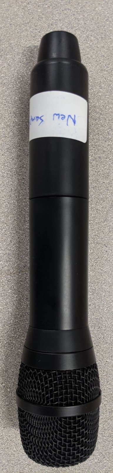
2AWPDAVTHHT1
Jan 19, 2021Handheld Wireless Microphone
Equipment Class
DWM - Part 15 Wireless Microphone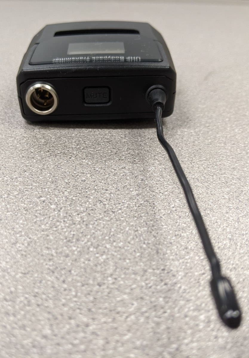
2AWPDAVTBPT1
Jan 19, 2021Bodyworn Wireless Microphone
Equipment Class
DWM - Part 15 Wireless Microphone