2AWPDAVTBPT1Bodyworn Wireless Microphone
Kingdom Inc.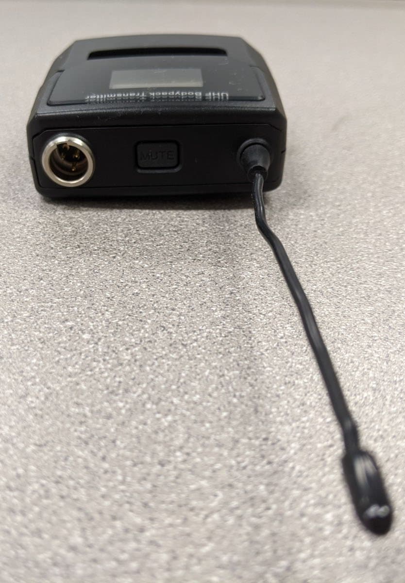
Click to zoom
Application Details
- Equipment Class
- DWM - Part 15 Wireless Microphone
- Date of Grant
- Jan 19, 2021
- Application Purpose
- Original Equipment
- Date of Application
- Jan 19, 2021
- Equipment Note
- Bodyworn Wireless Microphone
- Frequency Range
- 470.00000000 - 505.00000000
- Company
- Kingdom Inc.
- Country
- United States
Documents & Files
Document Text
Text extracted from the exhibit documents filed with the FCC. Open a document above to read the original.
Users Manual
Professional 200 Channel UHF Wireless Microphone Systems Profesionales UHF Sistemas de Micrófono Inalámbrico Professional Wireless Microphone Systems PLL Diversity Wireless Systems Please read and keep for future reference. USERS MANUAL FOR PROFESSIONAL UHF WIRELESS MICROPHONE SYSTEMS: (4 Mic Systems, 2 Mic Systems, and 1 Mic Systems) 719 SR 1001 Mansfield, PA 16933 U.S.A. www.nuselldistributing.com Product: Made in China Manual: Printed in China 2 Congratulations on Purchasing an AVTronics Wireless Microphone System! This product should give you trouble free service throughout it's life. We trust you will enjoy it's performance. FCC INFORMATION Kingdom Inc. 4 MIC RECEIVER: AVT4MR THIS DEVICE COMPLIES WITH PART 15 OF THE FCC RULES. OPERATION IS SUBJECT TO THE FOLLOW- ING TWO CONDITIONS: (1) THIS DEVICE MAY NOT CAUSE HARMFUL INTERFERENCE, AND (2) THIS DEVICE MUST ACCEPT ANY INTERFERENCE RECEIVED, INCLUDING INTERFERENCE THAT MAY CAUSE UNDESIRED OPERATION. TRANSMITTERS: * * * CONSUMER ALERT * * * Most users do not need a license to operate this wireless microphone system. Nev- ertheless, operating this microphone system without a license is subject to certain restrictions: the system may not cause harmful interference; it must operate at a low power level (not in excess of 50 milliwatts); and it has no protection from interference received from any other device. Purchasers should also be aware that the FCC is currently evaluating use of wireless microphone systems, and these rules are subject to change. For more Information, call the FCC at 1-888-CALL-FCC (TTY: 1-888-TELL-FCC) or visit the FCC's wireless microphone website at www.fcc.gov/cgb/wirelessmicrophones. NOTE: The manufacturer, distributor, and supplier is not responsible for any radio or TV interference caused by unauthorized modifications to this equipment. Such modifi- cations could void the user's authority to operate the equipment. FCC Information .................................... 2 Features and Specifications ................ 3 Getting Started ................................... 4-5 Receiver Helpful Diagrams 4 Mic System ................................. 6-7 2 Mic System ................................... 8 1 Mic System ................................... 9 AV T4 M R Handheld Bodypack/Beltpack Part #: AVTHHT1 Part #: AVTBPT1 FCC ID: 2AWPDAVTHHT1 FCC ID: 2AWPDAVTBPT1 INDEX Handheld Transmitter ........................... 10 Beltpack Transmitter ............................. 11 IR Sync .................................................. 12 Troubleshooting ............................... 13 -14 Notes ..................................................... 15 FEATURES & SPECIFICATIONS Handheld Transmitter (AVTHHT1) Specifications Carrier Wave Frequency Range: UHF 470~505MHz Frequency Response: 50Hz~18KHz Working Distance: Nearly 200 feet Transmitter Power: ~30mW Display: LCD Features Requires 2 AA batteries IR sync capable Bodypack / Beltpack Transmitter (AV TBPT1) Specifications Carrier Wave Frequency Range: UHF 470~505MHz Frequency Response: 50Hz~18KHz possible with beltpack. Actual will depend on mic attached. Working Distance: Nearly 200 feet Transmitter Power: ~30mW Display: LCD Beltpack Jack: 3.5mm / 1/8 inch lockable jack and mini XLR Features Lapel mic included Requires 2 AA battelies IR sync capable WARNINGS CAUTION! WARNING! Risk of harmful electric shock! Do not open the device! Opening may result in serious injury! Advertencia: Riesgo de un choque eléctrico. No abra el aparato. El abrirlo puede causar serias heridas. Do not dispose of this device by putting in the trash. Receiver (AV T4 M R) Specifications Carrier Wave Frequency Range: UHF 470~505MHz Display: OLED External Wall Wart Power Supply Output Connectors: Balanced XLR and Unbalanced 1/4 inch (TRS 6.35mm) Features IR sync capable Frequency selection mode Volume control Auto scan Group select Opening the device may void your warranty. 3 GETTING STARTED Put 2 batteries into each of your transmitters. The handheld takes 2 AA batteries and the battery compartment can be located by unscrewing the bottom of the handle. The belt- pack takes 2 AA batteries and the compart- ment can be located by swinging open the door. See diagrams on pages 10 and 11. Attach the two antennae to the back of your receiver. Attach by screwing onto the receiver in the proper location. See picture of your receiver on pages 6, 8 or 9 for help with locat- ing the proper location. Connect your sound system to your wireless microphone system using either 1/4" or XLR cables but not both at the same time. You will need to attach 1 XLR cable for each transmit- ter that you will be operating. For all receivers, when opting to use a 1/4" cable (instead of XLR cables) then only one 1/4" cable needs to be used per receiver regardless of how many transmitters you are operating with that receiver. Generally a cleaner more clear sound can be attained by using XLR cables. We highly rec- ommend the use of XLR cables instead of a 1/4" cable with your system. Plug the wall wart power supply into the back of your receiver and then into an electrical out- let. Power on your receiver using the power switch. Power on your transmitter. Handheld: Use the power button to power on the device. Beltpack: Power on using the button located on the central panel of the beltpack. Push power button for 3 seconds. See diagram on page 11. Now you must sync your transmitter and receiver to the same frequency or channel. By using the receiver controller on your receiver you can toggle through the various receiver settings and choose the IR sync mode. The receivers allow you to access IR sync mode by simply hitting the button on your receiver that says "IR SYNC". If you are going to be using more than one transmitter at a time then each transmitter must be set to a different frequency or chan- nel. You can use the receiver controller to select different frequencies (or channels) for additional transmitters. Choose a frequency o…
Text truncated - open the document above for the full version.
External Photos
Kingdom Inc. FCC ID: 2AWPDAVTBPT1 External Photographs Front Fro nt, Battery Case Open Ba ck External Photographs Left Right External Photographs Top Bottom
ID Label/Location Info
Kingdom Inc. FCC ID: 2AWPDAVTBPT1 Label sample and location
Internal Photos
Job # 1990-20, Kingdom Inc. Belt Pack Wireless Microphone Internal Photographs, Revision 2 RF PCB Front Antenna Internal Photographs RF PCB Back Antenna Internal Photographs Control PCB Front Internal Photographs Control PCB Back
RF Exposure Info
© 2020 RF Exposure Lab, LLC This report shall not be reproduced except in full without the written approval of RF Exposure Lab, LLC. 802 N. Twin Oaks Valley Road, Suite 105 • San Marcos, CA 92069 • U.S.A. TEL (760) 471-2100 • FAX (760) 471-2121 http://www.rfexposurelab.com CERTIFICATE OF COMPLIANCE SAR EVALUATION Kingdom Inc. Dates of Test: December 30, 2020 719 Lambs Creek Road Test Report Number: SAR.20201212 Mansfield, PA 16933 Revision A This wireless mobile and/or portable device has been shown to be compliant for localized specific absorption rate (SAR) for uncontrolled environment/general exposure limits specified in ANSI/IEEE Std. C95.1-1992 and had been tested in accordance with the measurement procedures specified in IEEE 1528-2013 and IEC 62209-2:2010 (See test report). I attest to the accuracy of the data. All measurements were performed by myself or were made under my supervision and are correct to the best of my knowledge and belief. I assume full responsibility for the completeness of these measurements and vouch for the qualifications of all persons taking them. RF Exposure Lab, LLC certifies that no party to this application is subject to a denial of Federal benefits that includes FCC benefits pursuant to Section 5301 of the Anti-Drug Abuse Act of 1988, 21 U.S.C. 853(a). Jay M. Moulton Vice President Testing Cert. # 2387.01 FCC ID: 2AWPDAVTBPT1 Model(s): AVTBPT1 Test Sample: Engineering Unit Same as Production Serial Number: Eng 1 Equipment Type: Wireless Body Worn Microphone Classification: Portable Transmitter Next to Body TX Frequency Range: 470 – 505 MHz Frequency Tolerance: ± 2.5 ppm Maximum RF Output: 16.99 dBm Conducted Signal Modulation: FM Antenna Type: Whip Antenna Battery Type: Alkaline AA Application Type: Certification FCC Rule Parts: Part 2, 74 KDB Test Methodology: KDB 447498 D01 v06 Maximum SAR Value: 0.12 W/kg Reported Separation Distance: 0 mm Report Number: SAR.20201212 © 2020 RF Exposure Lab, LLC Page 2 of 55 This report shall not be reproduced except in full without the written approval of RF Exposure Lab, LLC. Table of Contents 1. Introduction ........................................................................................................................ 4 SAR Definition [5] ................................................................................................................... 5 2. SAR Measurement Setup ................................................................................................... 6 Robotic System ...................................................................................................................... 6 System Hardware ................................................................................................................... 6 System Electronics ................................................................................................................. 7 Probe Measurement System .................................................................................................. 7 3. Probe and Dipole Calibration .............................................................................................15 4. Phantom & Simulating Tissue Specifications .....................................................................16 Head & Body Simulating Mixture Characterization ................................................................16 5. ANSI/IEEE C95.1 – 1992 RF Exposure Limits [2] ..............................................................17 Uncontrolled Environment .....................................................................................................17 Controlled Environment .........................................................................................................17 6. Measurement Uncertainty .................................................................................................18 7. System Validation..............................................................................................................19 Tissue Verification .................................................................................................................19 Test System Verification ........................................................................................................19 8. SAR Test Data Summary ..................................................................................................20 Procedures Used To Establish Test Signal ...........................................................................20 Device Test Condition ...........................................................................................................20 SAR Data Summary – 450 MHz Body ...................................................................................22 9. Test Equipment List ...........................................................................................................23 10. Conclusion ....................................................................................................................24 11. References ....................................................................................................................25 Appendix A – System Validation Plots and Data .......................................................................26 Appendix B – SAR Test Data Plots ...........................................................................................29 Appendix C – SAR Test Setup Photos ......................................................................................31 A ppendix D – Probe Calibration Data Sheets ............................................................................34 Appendix E – Dipole Calibration Data Sheets ...........................................................................44 Appendix F – Phantom Calibration Data Sheets .......................................................................53 Appendix G – Validation Summary .....................................…
Text truncated - open the document above for the full version.
Test Report
Timco Test Report # TR_1990-20_FCC_15.236_4 Revision: 4 Issue Date: October 26, 2020 Final Test Date: July 27, 2020 An IIA Company Te s t Report - FCC PART 15.236 DWM Prepared For: KINGDOM INC. Approved for Release By: Signature: Name & Title: Bruno Clavier, General Manager Date of Signature (YYYY-MM-DD): 2020-10 -26 This test report shall not be reproduced except in full without the written and signed permission of Timco Engineering Inc. (IIA). This test report relates only to the items tested as identified and is not valid for any subsequent changes or modifications made to the equipment under test. Timco Engineering, Inc., an IIA Company 849 NW State Road 45, Newberry, Florida 32669 (352) 472-5500 / [email protected] Page 2 of 30 This test report shall not be reproduced except in full without the written and signed permission of Timco Engineering Inc. (IIA). Table of Contents 1. CUSTOMER INFORMATION ....................................................................................................................................................................................................................... 3 1.1 T EST RESULT SUMMARY ........................................................................................................................................................................................................................................... 3 2. LOCATION OF TESTING ............................................................................................................................................................................................................................. 5 2.1 T EST LABORATORY ................................................................................................................................................................................................................................................... 5 2.2 T ESTING WAS PERFORMED, REVIEWED BY ................................................................................................................................................................................................................ 5 3. TEST SAMPLE(S) (EUT/DUT) ....................................................................................................................................................................................................................... 6 3.1 D ESCRIPTION OF THE EUT ....................................................................................................................................................................................................................................... 6 3.2 C ONFIGURATION OF EUT ........................................................................................................................................................................................................................................ 7 3.3 T EST SETUP OF EUT................................................................................................................................................................................................................................................. 7 4. TEST METHODS & APPLICABLE REGULATORY LIMITS .......................................................................................................................................................................... 8 4.1 T EST METHODS/STANDARDS/GUIDANCE: ............................................................................................................................................................................................................... 8 4.2 A PPLIED LIMITS AND REGULATORY LIMITS: ............................................................................................................................................................................................................. 8 5. MEASUREMENT UNCERTAINTY ................................................................................................................................................................................................................ 8 6. ENVIRONMENTAL CONDITIONS .............................................................................................................................................................................................................. 8 6.1 T EMPERATURE & HUMIDITY ..................................................................................................................................................................................................................................... 8 7. LIST OF TEST EQUIPMENT AND TEST FACILITY ...................................................................................................................................................................................... 9 7.1 L IST OF TEST EQUIPMENT ........................................................................................................................................................................................................................................ 9 8. TEST RESULTS ............................................................................................................................................................................................................................................. 10 8.1 OUTPUT POWER ..................................................................................................................................................................................................................................................... 11 8.1.1 Output Power, 470.125 MHz ............................................................................................................................................................................................................ 12 8.1.2 Output Power, 486.425 MHz ..........................................................…
Text truncated - open the document above for the full version.
Test Setup Photos
TEST SETUP PHOTOGRAPHS Applicant: KINGDOM INC. FCC ID: 2AWPDAVTBPT1 Table Top TEST SETUP PHOTOGRAPHS FIELD STRENGTH OF SPURIOUS EMISSIONS TEST SETUP PHOTOGRAPHS FIELD STRENGTH OF SPURIOUS EMISSIONS
Contact Information
Applicant
John Berguson(President)
Test Firm
Timco Engineering, Inc.Bruno Clavier
Technical Specifications
| # | Rule Parts | Frequency Range | Power Output | Tolerance |
|---|---|---|---|---|
| 1 | 15C | 470 MHz - 505 MHz | 50.00 mW | 1650.0000000000 Hz |
Other Applications from Kingdom Inc.

2AWPD-HHK7000
Dec 04, 2025Handheld Wireless Microphone Transmitter
Equipment Class
DWM - Part 15 Wireless Microphone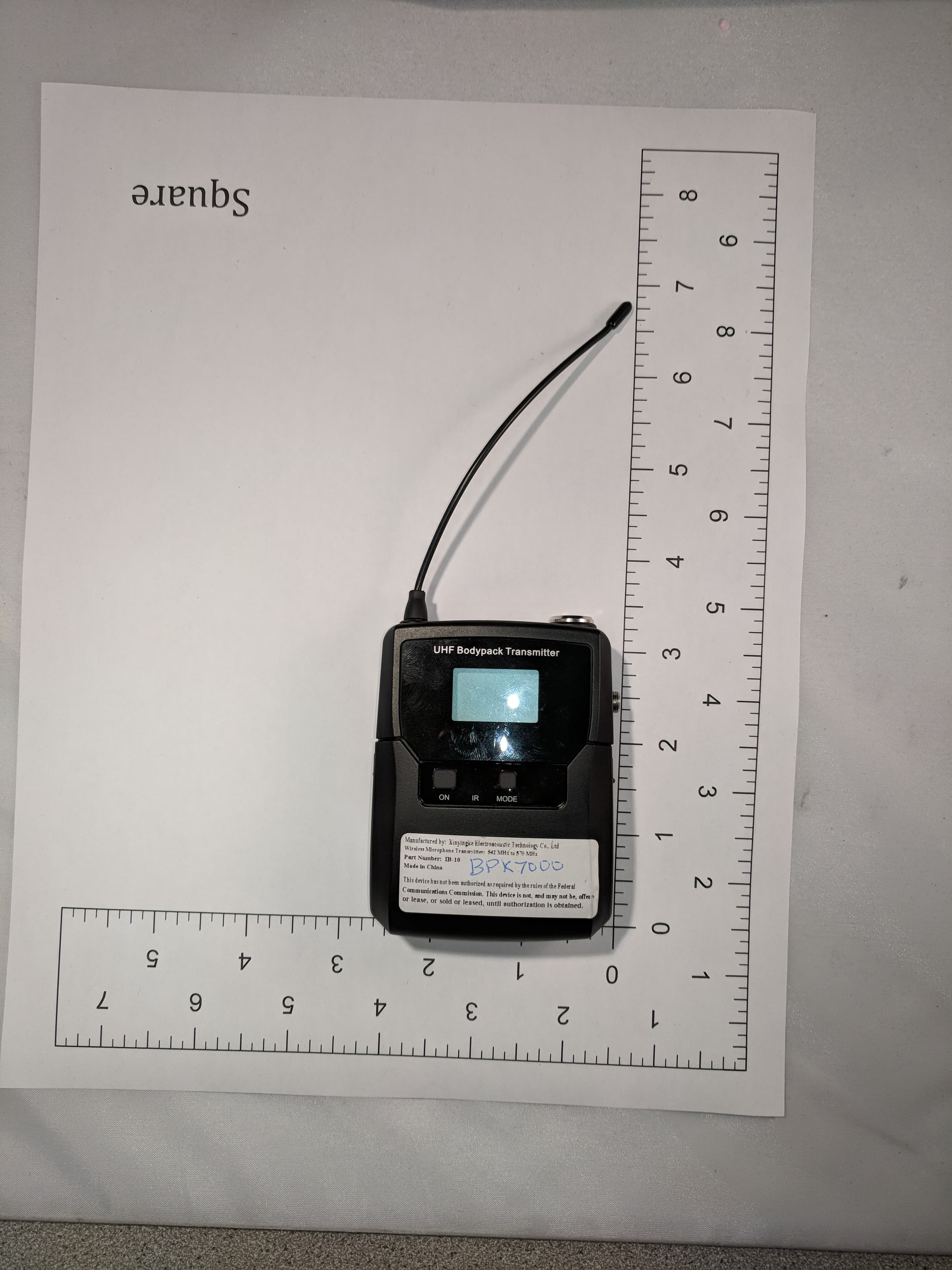
2AWPD-BPK7000
Dec 04, 2025Bodypack Transmitter for Wireless Microphone System
Equipment Class
DWM - Part 15 Wireless Microphone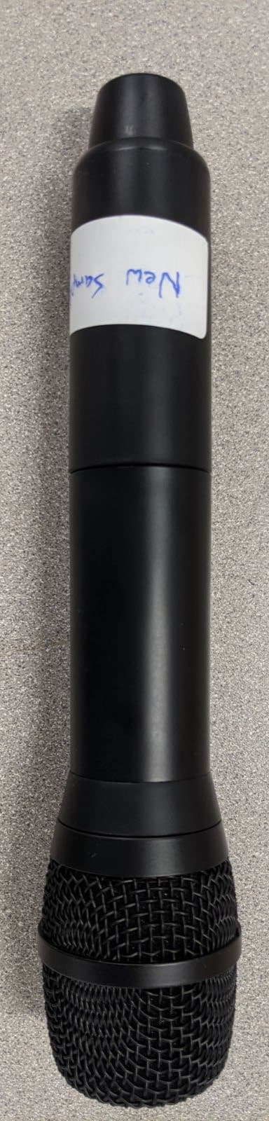
2AWPDAVTHHT1
Jan 19, 2021Handheld Wireless Microphone
Equipment Class
DWM - Part 15 Wireless Microphone