2AWPP-ASL220Smart Lock
Arize Corporation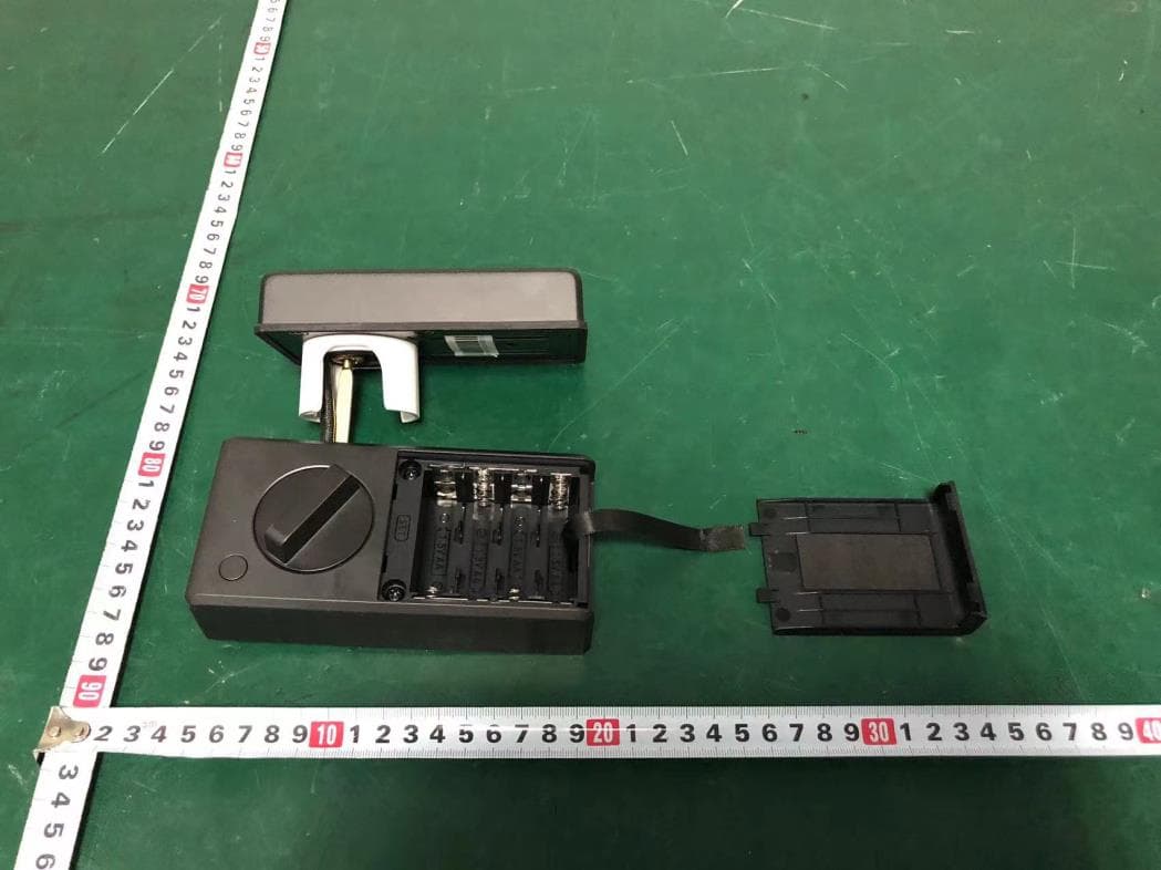
Click to zoom
Application Details
- Equipment Class
- DTS - Digital Transmission System
- Date of Grant
- Aug 03, 2024
- Application Purpose
- Original Equipment
- Date of Application
- Aug 03, 2024
- Equipment Note
- Smart Lock
- Frequency Range
- 2405.00000000 - 2480.00000000
- Company
- Arize Corporation
- Country
- United States
Documents & Files
Document Text
Text extracted from the exhibit documents filed with the FCC. Open a document above to read the original.
Users Manual
1. This device complies with Part 15 of the FCC Rules. Operation is subject to the following two conditions: (1) This device may not cause harmful interference, and (2) This device must accept any interference received, including interference that may cause undesired operation. 2. Changes or modifications not expressly approved by the party responsible for compliance could void the user's authority to operate the equipment. NOTE: This equipment has been tested and found to comply with the limits for a Class B digital device, pursuant to Part 15 of the FCC Rules. These limits are designed to provide reasonable protection against harmful interference in a residential installation. This equipment generates uses and can radiate radio frequency energy and, if not installed and used in accordance with the instructions, may cause harmful interference to radio communications. However, there is no guarantee that interference will not occur in a particular installation. If this equipment does cause harmful interference to radio or television reception, which can be determined by turning the equipment off and on, the user is encouraged to try to correct the interference by one or more of the following measures: Reorient or relocate the receiving antenna. Increase the separation between the equipment and receiver. Connect the equipment into an outlet on a circuit different from that to which the receiver is connected. Consult the dealer or an experienced radio/TV technician for help. Radiation Exposure Statement This equipment complies with FCC radiation exposure limits set forth for an uncontrolled environment. This equipment should be installed and operated with minimum distance 20cm between the radiator & your body. FCC SDOC SUPPLIER'S DECLARATION OF CONFORMITY Arize Corporation hereby declares that this equipment is in compliance with the FCC rules. The declaration of conformity may be consulted in the support section of our Web site, accessible from www.arizehub.com FCC STATEMENT - English: This device contains licence-exempt transmitter(s)/receiver(s) that comply with Innovation, Science and Economic Development Canada’s licence-exempt RSS(s). Operation is subject to the following two conditions: (1) This device may not cause interference. (2) This device must accept any interference, including interference that may cause undesired operation of the device. RF warning statement: This equipment complies with IC radiation exposure limits set forth for an uncontrolled environment. This equipment should be installed and operated with minimum distance 20cm between the radiator & your body. - French: L’émetteur/récepteur exempt de licence contenu dans le présent appareil est conforme aux CNR d’Innovation, Sciences et Développement économique Canada applicables aux appareils radio exempts de licence. L’exploitation est autorisée aux deux conditions suivantes : 1) L’appareil ne doit pas produire de brouillage; 2) L’appareil doit accepter tout brouillage radioélectrique subi, même si le brouillage est susceptible d’en compromettre le fonctionnement Avertissement RF: Cet appareil est conforme à IC l’exposition aux rayonnements limites fixées pour un environnement non contrôlé. Cet appareil doit être installé et utilisé avec une distance minimale de 20 cm entre le radiateur et votre corps. Cet transmetteur ne doit pas être co-situé ou opérant en liaison avec toute autre antenne ou transmetteur. IC warning Press the "set" button of the interior lock for 1-2 seconds in standby mode, and release it when the lock body broadcasts the voice "Please turn on the app pairing lock", and the lock body will enter the network distribution mode. At this time, the light bar on the front panel of the door lock will light up blue and cycle on and off. The entire network distribution mode will last for about 3 minutes, during which the front lock panel will not respond to other operations. During the network configuration process, if the binding is successful, the lock will broadcast "Device has been paired" and the light bar will turn off. The door lock returns to normal state, and the initial password (if any) becomes invalid. Please note that after the initial password is set, the lock can only be unlocked through the thumbturn, key, interior lock button, and initial password verification. aAfter correctly installing the lock onto the door, ensure that the lock tongue can extend normally without obstructionInsert 8pcs AA batteries; bWhen the lock is not connected to the network, enter any 4-8 digit password and press the confirm key "√" and able to unlock cUnlocking status, touch any key and able to lock 4) Input 4-8 digits password 5) Click“√”for next stepPlease note that if the number of digits entered does not meet the requirements of 4-8 digits or is too simple, the lock will voice a corresponding warning, and the user needs to enter it again 6) Re-enter the initialized passwordclick “√”for confirmation, if password does not match, lock voices “The access code do not match please re-enterif password matchedvoices “Initial access code setting complete”password initiated succeedclick “×”and able to removed password entered and restart the configuration again aRemove battery cover, quick click “set”button twice within 2 seconds direction of smart lock will be calibrated automatically then voice “calibrate successfully”once succeed 1.First use 2.Calibrate the direction of the lock 5. Thread the cable through the through-hole on the backplane and fix the exterior assembly with screws through the backplane Choose the appropriate length of screws based on the thickness of the door Default distance is 60mmif necessary changed to 70mmGrasp both ends of the lock body and rotate them 180 degrees. Extend the lock body to a center distance of 70mm, then rotate it in the opposite direction by another 180 degrees to change back to the original center distance Warning: Phillips scewdriver Screws Deadbolt Exterior Assembly Interior …
Text truncated - open the document above for the full version.
Attestation Statements
Arize Corporation * the applicant must designate a contact located in the United States for purposes of acting as the applicant’s agent for service of process, regardless of whether the applicant is a domestic or foreign entity. An applicant located in the United States may designate itself as the agent for service of process. U.S. Agent Designation for Service of Process - Certification Attestation Letter 5/30/2024 Federal Communications Commission Authorization and Evaluation Division 7435 Oakland Mills Road Columbia, MD 21046 USA ATTN.: Reviewing Engineer FCC ID: 2AWPP-ASL220 FRN of applicant: 0029688017 Per section 2.911(d)(7) of the FCC rules, Arize Corporation (“the applicant”) certifies that the equipment for which authorization is sought is designated to the following U.S. agent* for service of process: Company Name: Arize Corporation FCC Registration Number (FRN): 0029688017 Physical U.S. Company Address: 1065 N Pacificenter Drive,Suite 410,Anaheim,CA 92806,USA Contact Person: Wayne pan Agent Email Address: [email protected] The above contact person accepts the obligation for service of process. The applicant accepts to maintain an agent for no less than one year after the grantee has terminated all marketing and importation or the conclusion of any Commission-related proceeding involving the equipment. Applicant Signed: Agent Signed (if different from Applicant): Signed: Signed: Printed name: Wayne pan Printed name: Wayne pan Title: Senior Manager Title: Senior Manager Company Name: Arize Corporation Company Name: Arize Corporation Date: 7/29/2024 Date: 7/29/2024
Attestation Statements
Arize Corporation Covered Equipment Certification Attestation Letter 7/29/2024 Federal Communications Commission Authorization and Evaluation Division 7435 Oakland Mills Road Columbia, MD 21046 USA ATTN.: Reviewing Engineer FCC ID: 2AWPP-ASL220 Arize Corporation (“the applicant”) certifies that, as of the date of the filing of the application, the applicant is not identified on the Covered List as an entity producing “covered” equipment. Signed: Printed name: Wayne pan Title: Senior Manager Company Name: Arize Corporation Date: 7/29/2024
Attestation Statements
Arize Corporation Covered Equipment Certification Attestation Letter 7/29/2024 Federal Communications Commission Authorization and Evaluation Division 7435 Oakland Mills Road Columbia, MD 21046 USA ATTN.: Reviewing Engineer FCC ID: 2AWPP-ASL220 Arize Corporation (“the applicant”) certifies that the equipment for which authorization is sought is not “covered” equipment prohibited from receiving an equipment authorization pursuant to section 2.903 of the FCC rules. Note: If the equipment for which the applicant seeks authorization is produced by any of the entities identified on the current Covered List, the applicant should include an explanation on why the equipment is not “covered” equipment. Signed: Printed name: Wayne pan Title: Senior Manager Company Name: Arize Corporation Date: 7/29/2024
Cover Letter(s)
DATE : 7/30/2024 Equipment Autorisation Division Federal Communications Commission 7435 Oakland Mills Road Columbia, MD 21046 FCC ID: 2AWPP-ASL220 Product Name: Smart Lock Request for Confidentiality Pursuant to Sections 0.457 and 0.459 of the commissions rules, we hereby request that the following documents be held confidential: Schematics Block diagram Operation description These materials contain trade secrets and proprietary information and are not customarily released to the public. The public disclosure of this information might be harmful to the company and provide unjustified benefits to our competitors. <Signature> Name:Wayne pan Title:Senior Manager Company:Arize Corporation
Cover Letter(s)
DATE : 7/30/2024 Federal Communications Commission Authorization & Evaluation Division 7345 Oakland Mills Road Columbia, Maryland 21046 RE: LETTER OF AGENT AUTHORIZATION To Whom It May Concern: We, the undersigned, hereby authorize Compliance Testing, LLC to act on our behalf in all matters relating to application for equipment authorization, including the signing of all documents relating to these matters. We also hereby certify that no party to the application authorized hereunder is subject to the denial of benefits, including FCC benefits, pursuant to Section 5301 of the Anti-Drug Abuse Act of 1988, 21 U.S.C.853(a). Sincerely, <Signature> Name:Wayne pan Title:Senior Manager Company:Arize Corporation
Cover Letter(s)
DATE : 7/30/2024 Federal Communications Commission Authorization & Evaluation Division 7345 Oakland Mills Road Columbia, Maryland 21046 Authority to Act as Agent On our behalf, I appoint EST Technology Co., Ltd. Address:Chilingxiang, Qishantou, Santun, Houjie, Dongguan, Guangdong, China to act as our agent in the preparation of this application for equipment certification. I certify that submitted documents properly describe the device or system for which equipment certification is sought. I also certify that each unit manufactured, imported or marketed, as defined in the Federal Communications Commission’s regulations will have affixed to it a label identical to that submitted for approval with this application. For instances where our authorized agent signs the application for certification on our behalf, I acknowledge that all responsibility for complying with the terms and conditions for certification, still resides with Arize Corporation Address: 1065 N Pacificenter Drive,Suite 410,Anaheim,CA 92806,USA <Signature> Name:Wayne pan Title:Senior Manager Applicant Company:Arize Corporation
External Photos
External Photos M/N: ASL220 External Photos M/N: ASL220 External Photos M/N: ASL220 External Photos M/N: ASL220
ID Label/Location Info
60 mm 25 mm 罗茜 20240430空白不干胶 粘贴位置:后锁底部;需二次加工,来料卷装一出一,其它按公司标准。 尺寸60*25mm 公差:+-0.2mm,R=1/5 80G铜版纸不干胶贴纸 A Model No.: ASL220 Voltage: 4.5V-6.5V FCC ID: 2AWPP-ASL220 IC: 32374-ASL220 This device complies with Part 15 of the FCC Rules. Operation is subject to the following two conditions: (1) This device may not cause harmful interference, and (2) This device must accept any interference received, including interference that may cause undesired operation. Roboto-Condensed 5pt Roboto-Condensed 6.5pt Roboto-Condensed 5pt PO++ Made in China B/N: XXXXXXXXXXXXXXXXXX Smart Lock Model No.:ASL220 Voltage: 4.5V-6.5V FCC ID:2AWPP-ASL220 IC:32374-ASL220 Tinis device complies with Part 15 of the FCC Rules. Operation is subject to the following two conditions: (1) This device may not cause harmful interference, and (2) This device must accept any interference received, including interference that may cause undesired operation. B/N: XXXXXXXXXXXXXXXXXX Smart Lock
Internal Photos
Internal Photos M/N: ASL220 Internal Photos M/N: ASL220 Internal Photos M/N: ASL220 Internal Photos M/N: ASL220 Zigbee antenna Internal Photos M/N: ASL220 Internal Photos M/N: ASL220 Bluetooth Antenna Internal Photos M/N: ASL220 Internal Photos M/N: ASL220
RF Exposure Info
Page 1 of 4 Report No. ESTE-R2404244 FCC 47 CFR MPE REPORT Arize Corporation Smart Lock Model Number: ASL220 FCC ID: 2AWPP-ASL220 Applicant: Arize Corporation Address: 1065 N Pacificenter Drive, Suite 410, Anaheim, California 92806, United States Prepared By: EST Technology Co., Ltd. Chilingxiang, Qishantou, Santun, Houjie, Dongguan, Guangdong, China Tel: 86-769-83081888-808 Report Number: ESTE-R2404244 Date of Test: Apr. 15 ~ Apr. 28, 2024 Date of Report: Apr. 30, 2024 Page 2 of 4 Report No. ESTE-R2404244 Maximum Permissible Exposure 1. Applicable Standards Systems operating under the provisions of this section shall be operated in a manner that ensures that the public is not exposed to radio frequency energy level in excess limit for maximum permissible exposure. In accordance with 47 CFR FCC Part 2 Subpart J, section 2.1091 this device has been defined as a mobile device whereby a distance of 0.2m normally can be maintained between the user and the device. 1.1. Limits for Maximum Permissible Exposure (MPE) (a) Limits for Occupational/Controlled Exposure Frequency Range (MHz) Electric Field Strength (E) (V/m) Magnetic Field Strength (H) (A/m) Power Density (S) (mW/cm 2 ) Averaging Times ︱E︱ 2 ,︱H︱ 2 or S (minutes) 0.3-3.0 614 1.63 (100)* 6 3.0-30 1842/f 4.89/f (900/f)* 6 30-300 61.4 0.163 1.0 6 300-1500 F/300 6 1500-10000 5 6 (b) Limits for General Population / Uncontrolled Exposure Frequency Range (MHz) Electric Field Strength (E) (V/m) Magnetic Field Strength (H) (A/m) Power Density (S) (mW/cm 2 ) Averaging Times ︱E︱ 2 ,︱H︱ 2 or S (minutes) 0.3-1.34 614 1.63 (100)* 30 1.34-30 824/f 2.19/f (180/f)* 30 30-300 27.5 0.073 0.2 30 300-1500 F/1500 30 1500-10000 1.o 30 Note: f=frequency in MHz; *Plane-wave equivalent power density Page 3 of 4 Report No. ESTE-R2404244 1.2. MPE Calculation Method E (V/m) = d G × P × 30 Power Density: Pd (W/m 2 ) = 377 E 2 E = Electric Field (V/m) P = Peak RF output Power (W) G = EUT Antenna numeric gain (numeric) d = Separation distance between radiator and human body (m) The formula can be changed to Pd = 2 d × 377 G × P × 30 From the peak EUT RF output power, the minimum mobile separation distance, d=0.2m, as well as the gain of the used antenna, the RF power density can be obtained Page 4 of 4 Report No. ESTE-R2404244 2. Conducted Power Result Mode Frequency (MHz) Peak output power (dBm) Peak output power (mW) BLE 1M 2402 5.66 3.681 2440 5.88 3.873 2480 5.56 3.597 BLE 2M 2402 5.94 3.926 2440 5.90 3.890 2480 5.62 3.648 ZIGB 2405 8.71 7.430 2440 9.26 8.433 2480 8.99 7.925 3. Calculated Result and Limit Mode Peak output power (dBm) Target power (dBm) MAX Target power (dBm) Antenna gain Power Density (S) (mW/cm 2 ) Limited of Power Density (S) (mW/cm 2 ) Test Result (dBi) (Linear) 2.4G Band BLE 1M 5.88 5±1 6 -3.41 0.456 0.00036 1 Complies BLE 2M 5.94 5±1 6 -3.41 0.456 0.00036 1 Complies ZIGB 9.26 9±1 10 3.45 2.213 0.00440 1 Complies Simultaneous Transmissions Mode Result Limit Simultaneous Transmissions Result Simultaneous Transmissions Limit Total Result BLE 0.00036 1 0.00476 1 Complies ZIGB 0.00440 1 End of Test Report
Test Report
Page 1 of 72 Report No.ESTE-R2404242 FCC PART 15C TEST REPORT FOR CERTIFICATION On Behalf of Arize Corporation Smart Lock Model Number: ASL220 FCC ID: 2AWPP-ASL220 Applicant : Arize Corporation Address: 1065 N Pacificenter Drive, Suite 410, Anaheim, California 92806, United States Prepared By: EST Technology Co., Ltd. Chilingxiang, Qishantou, Santun, Houjie, Dongguan, Guangdong, China Tel: 86-769-83081888-808 Report Number: ESTE-R2404242 Date of Test: Apr. 15 ~ Apr. 28, 2024 Date of Report: Apr. 30, 2024 Page 2 of 72 Report No.ESTE-R2404242 TABLE OF CONTENTS Description Page TEST REPORT VERIFICATION .......................................................................................................... 3 1. GENERAL INFORMATION ................................................................................................................... 5 1.1. Description of Device (EUT) ............................................................................................................ 5 1.2. Antenna Information ......................................................................................................................... 5 1.3. Information of RF Cable ................................................................................................................... 5 2. SUMMARY OF TEST ........................................................................................................................... 6 2.1. Summary of test result ..................................................................................................................... 6 2.2. Test Facilities ..................................................................................................................................... 7 2.3. Measurement uncertainty ................................................................................................................ 8 2.4. Assistant equipment used for test .................................................................................................. 8 2.5. Block Diagram ................................................................................................................................... 8 2.6. Test Mode .......................................................................................................................................... 9 2.7. Power Setting of Test Software ...................................................................................................... 9 2.8. Duty Cycle .......................................................................................................................................... 9 2.9. Channel List ..................................................................................................................................... 10 2.10. Test Equipment List ...................................................................................................................... 11 3. 6DB BANDWIDTH ............................................................................................................................ 13 3.1. Limit ................................................................................................................................................... 13 3.2. Test Setup ........................................................................................................................................ 13 3.3. Spectrum Analyzer Setting ............................................................................................................ 13 3.4. Test Procedure ................................................................................................................................ 13 3.5. Test Result ....................................................................................................................................... 13 4. MAXIMUM PEAK OUTPUT POWER .................................................................................................. 14 4.1. Limit ................................................................................................................................................... 14 4.2. Test Setup ........................................................................................................................................ 14 4.3. Spectrum Analyzer Setting ............................................................................................................ 14 4.4. Test Procedure ................................................................................................................................ 14 4.5. Test Result ....................................................................................................................................... 14 5. POWER SPECTRAL DENSITY .......................................................................................................... 15 5.1. Limit ................................................................................................................................................... 15 5.2. Test Setup ........................................................................................................................................ 15 5.3. Spectrum Analyzer Setting ............................................................................................................ 15 5.4. Test Procedure ................................................................................................................................ 15 5.5. Test Result ....................................................................................................................................... 15 6. CONDUCTED BAND EDGE .............................................................................................................. 16 6.1. Limit ................................................................................................................................................... 16 6.2. Test Setup .........................…
Text truncated - open the document above for the full version.
Test Report
Page 51 of 72 Report No.ESTE-R2404242 Appendix E: Band edge measurements Test Result Test Mode Antenna Ch Name Frequency[MHz] RefLevel[dBm] Result[dBm] Limit[dBm] Verdict BLE_1M Ant1 Low 2402 5.26 -40.7 ≤-14.74 PASS BLE_1M Ant1 High 2480 4.90 -41.47 ≤-15.1 PASS BLE_2M Ant1 Low 2402 3.14 -28.23 ≤-16.86 PASS BLE_2M Ant1 High 2480 3.49 -40.89 ≤-16.51 PASS Page 52 of 72 Report No.ESTE-R2404242 Test Graphs BLE_1M-Ant1-2402-PASS BLE_1M-Ant1-2480-PASS BLE_2M-Ant1-2402-PASS Page 53 of 72 Report No.ESTE-R2404242 BLE_2M-Ant1-2480-PASS Page 54 of 72 Report No.ESTE-R2404242 Appendix F: Conducted Spurious Emission Test Result TestMode Antenna Frequency[MHz] FreqRange [MHz] RefLevel [dBm] Result[dBm] Limit[dBm] Verdict BLE_1M Ant1 2402 30~26500 5.26 -42.8 ≤-14.74 PASS BLE_1M Ant1 2440 30~26500 5.54 -43.24 ≤-14.46 PASS BLE_1M Ant1 2480 30~26500 4.90 -43.24 ≤-15.1 PASS BLE_2M Ant1 2402 30~26500 3.14 -43.49 ≤-16.86 PASS BLE_2M Ant1 2440 30~26500 3.47 -43.6 ≤-16.53 PASS BLE_2M Ant1 2480 30~26500 3.49 -42.69 ≤-16.51 PASS Page 55 of 72 Report No.ESTE-R2404242 Test Graphs BLE_1M-Ant1-2402-30~26500-PASS BLE_1M-Ant1-2440-30~26500-PASS BLE_1M-Ant1-2480-30~26500-PASS Page 56 of 72 Report No.ESTE-R2404242 BLE_2M-Ant1-2402-30~26500-PASS BLE_2M-Ant1-2440-30~26500-PASS BLE_2M-Ant1-2480-30~26500-PASS Page 57 of 72 Report No.ESTE-R2404242 Appendix G: Duty Cycle Test Result TestMode Antenna Frequency[MHz] ON Time [ms] Period [ms] Duty Cycle [%] Duty Cycle Factor[dB] BLE_1M Ant1 2440 20.00 20.00 100.00 0.00 BLE_2M Ant1 2440 13.00 13.00 100.00 0.00 Page 58 of 72 Report No.ESTE-R2404242 Test Graphs NTNV-BLE_1M-Ant1-2440 NTNV-BLE_2M-Ant1-2440 Page 59 of 72 Report No.ESTE-R2404242 12. TEST SETUP PHOTO Conducted Test Page 60 of 72 Report No.ESTE-R2404242 Radiated Test (Below 1GHz) Radiated Test (Above 1GHz) Page 61 of 72 Report No.ESTE-R2404242 13. EUT PHOTO External Photos M/N: ASL220 Page 62 of 72 Report No.ESTE-R2404242 External Photos M/N: ASL220 Page 63 of 72 Report No.ESTE-R2404242 External Photos M/N: ASL220 Page 64 of 72 Report No.ESTE-R2404242 External Photos M/N: ASL220 Page 65 of 72 Report No.ESTE-R2404242 Internal Photos M/N: ASL220 Page 66 of 72 Report No.ESTE-R2404242 Internal Photos M/N: ASL220 Page 67 of 72 Report No.ESTE-R2404242 Internal Photos M/N: ASL220 Page 68 of 72 Report No.ESTE-R2404242 Internal Photos M/N: ASL220 Page 69 of 72 Report No.ESTE-R2404242 Internal Photos M/N: ASL220 Page 70 of 72 Report No.ESTE-R2404242 Internal Photos M/N: ASL220 Bluetooth Antenna Page 71 of 72 Report No.ESTE-R2404242 Internal Photos M/N: ASL220 Page 72 of 72 Report No.ESTE-R2404242 Internal Photos M/N: ASL220 End of Test Report
Test Report
Page 1 of 65 Report No. ESTE-R2404243 FCC PART 15C TEST REPORT FOR CERTIFICATION On Behalf of Arize Corporation Smart Lock Model Number: ASL220 FCC ID: 2AWPP-ASL220 Applicant : Arize Corporation Address: 1065 N Pacificenter Drive, Suite 410, Anaheim, California 92806, United States Prepared By: EST Technology Co., Ltd. Chilingxiang, Qishantou, Santun, Houjie, Dongguan, Guangdong, China Tel: 86-769-83081888-808 Report Number: ESTE-R2404243 Date of Test: Apr. 15 ~ Jun. 28, 2024 Date of Report: Jul. 03, 2024 Page 2 of 65 Report No. ESTE-R2404243 TABLE OF CONTENTS Description Page TEST REPORT VERIFICATION .......................................................................................................... 3 1. GENERAL INFORMATION ................................................................................................................... 5 1.1. Description of Device (EUT) ............................................................................................................ 5 1.2. Antenna Information ......................................................................................................................... 5 1.3. Information of RF Cable ................................................................................................................... 5 2. SUMMARY OF TEST ........................................................................................................................... 6 2.1. Summary of test result ..................................................................................................................... 6 2.2. Test Facilities ..................................................................................................................................... 7 2.3. Measurement uncertainty ................................................................................................................ 8 2.4. Assistant equipment used for test .................................................................................................. 8 2.5. Block Diagram ................................................................................................................................... 8 2.6. Test Mode .......................................................................................................................................... 9 2.7. Power Setting of Test Software ...................................................................................................... 9 2.8. Duty Cycle ........................................................................................................................................ 10 2.9. Channel List ..................................................................................................................................... 10 2.10. Test Equipment List ...................................................................................................................... 11 3. 6DB BANDWIDTH ............................................................................................................................ 13 3.1. Limit ................................................................................................................................................... 13 3.2. Test Setup ........................................................................................................................................ 13 3.3. Spectrum Analyzer Setting ............................................................................................................ 13 3.4. Test Procedure ................................................................................................................................ 13 3.5. Test Result ....................................................................................................................................... 13 4. MAXIMUM PEAK OUTPUT POWER .................................................................................................. 14 4.1. Limit ................................................................................................................................................... 14 4.2. Test Setup ........................................................................................................................................ 14 4.3. Spectrum Analyzer Setting ............................................................................................................ 14 4.4. Test Procedure ................................................................................................................................ 14 4.5. Test Result ....................................................................................................................................... 14 5. POWER SPECTRAL DENSITY .......................................................................................................... 15 5.1. Limit ................................................................................................................................................... 15 5.2. Test Setup ........................................................................................................................................ 15 5.3. Spectrum Analyzer Setting ............................................................................................................ 15 5.4. Test Procedure ............................................................................................…
Text truncated - open the document above for the full version.
Contact Information
Applicant
Wayne pan(Senior Manager)
Test Firm
EST Technology Co., Ltd.Iceman Hu
[email protected]+86 0769-83081888
Technical Specifications
| # | Rule Parts | Frequency Range | Power Output |
|---|---|---|---|
| 2 | 15C | 2.40 GHz - 2.48 GHz | 9.79 mW |
Other Applications from Arize Corporation
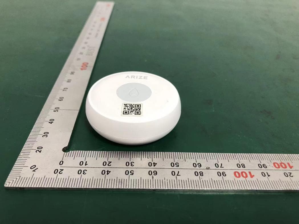
2AWPP-AWD310
Aug 02, 2024Water Detector
Equipment Class
DTS - Digital Transmission System
2AWPP-AST110
Jul 15, 2021Smart Thermostat
Equipment Class
DTS - Digital Transmission System