2AWPP-AST110Smart Thermostat
Arize Corporation
Click to zoom
Application Details
- Equipment Class
- DTS - Digital Transmission System
- Date of Grant
- Jul 15, 2021
- Application Purpose
- Original Equipment
- Date of Application
- Jul 15, 2021
- Equipment Note
- Smart Thermostat
- Frequency Range
- 2402.00000000 - 2480.00000000
- Company
- Arize Corporation
- Country
- United States
Documents & Files
Document Text
Text extracted from the exhibit documents filed with the FCC. Open a document above to read the original.
Users Manual
ARIZE Smart ThermostatAST110 UserManual R Wi-FiThermostatTwo screws andanchors WirelabelsJumperwire InstallationGuide AST110Smart Wi-Fi Thermostat Firstthingsfirst.Here’s whatyou’ll findinthebox Youmayalsoneedthesetools: Phillipsscrewdriver Pencil Level CompatibilitySectionForconventional(gas/oil/propane/electric)heat-pumpanddualfuel sy stems. >2-Heat&2-Cool>1-Heat&1Cool>HeatOnly>CoolOnly >HeatPumpwithAuxiliaryHeatingandEmergencyHeating C-Wirerequiredtopowerthethermostat Home Wi-FiPassword Incompatiblewiringandvoltage Pleasecheckyouroldthermostat’swallplatehaveanybelowindicators? • Doesnot work with electricbaseboardheat(110VAC~240VAC)• Doesnotworkwithmillivoltsystems• DoesnotsupportSterminalsforindoorsandoutdoorssensors. 110 or VAC 120 or VAC 240 VAC L1 L2 Download the App Search Arize Resident in the App Store or Google Play Store ,then download Step 1 Switch o ff power Installation ThisAST110thermostatisdesignedtoworkonmost24V-ACowvoltageheatin gandcoolingsystems suchas gasandoilfurnaces,heatpumps,andsingleordual-stagesystems.Thisprotectsyouandavoidsblowingafuseinyourequipment.Tomakesurethepoweriso ff ,changethe temperaturewithyourcurrentthermostatandwaitatleastfiveminutestobesurethatyoursystemdoesn’tturnon. Breaker Box Switch or ON OFF Step 2 Checkthatyoursystemiso ff Confirmyoursystemiso ff byturningonyourheat(duringwinter)oryourAC(during summer ).Waitafewminutes—youshouldnotfeelaircomingfromyourvents.NOTE : Ifyouhaveadigital thermostat with a blankdisplay,skipthis step. Step 3 Removeyouroldthermostatfromthewallplate Most thermostats allow you to remove the main unit and provide access to a wall plate wh ich holds the wiring terminals , you can take off the thermostat by grasping and gently pulling. Some thermostats may have screws, buttons, or clasps.NOTE : Donotremoveanywiresfromyourthermostatat this time! Step 4 Takeapictureofthewires Take a picture of your existing wall plate’s wiring and save it for reference. Make sure you can read the wire terminal labels. Step 5 Label thewires Use the wire label provided with your new thermostat to label each wire on your old wall plate.NOTE : IfyouhaveanRcorRhwire,puttheR label onit. Disconnect the wires from the old thermostat one by one, you may need a screwdriver to release wires from terminals.NOTE : Wrap the wires around a pen or pencil so they don’t fall back into the hole in the wall. Use the enclosed screws and anchors to mount the new wall plate. In most cases, you can utilize the same mounting position of your old thermostat. Be sure to check the alignment of your wall plate pre and post installation of the thermostat unit. Step 6 Disconnectthewiresandremovethe oldwallplate Step 7 Mount the New Wall Plate Com Ch p e a c t k ib e i r lity Lookatthethermostatwiringphotoyoutook.Thefollowingarewiringdiag ramsforcommon systems, pleaseconfirmyouhaveaCconnectedtoyouroldthermostat. Terminal ConventionalSystem Heat PumpSystem RC Power for cooling,24V Power for cooling,24V RH Power for heating,24V Power for heating,24V C Common wire,24V Common wire,24V G Fan Fan Y 1st StageCool 1st outdoor StageHeat Y2 2nd StageCool 2nd outdoor StageHeat W/E 1st StageHeat 1st Stage Auxiliary/EmergencyHeat O/B/W2 2nd StageHeat Changeover (reversing valve) connection for heat pump Thermostat RC RH 1st Stage Heat 2nd Stage Heat GW/EY C Y2O/B/W2 SingleStageHeat/TwoStageHeat-Furnace/BoilerwithCwire RC RH G W/E Y C Y2 O/B/W2 Combined Single Stage Heat and Single Cool Stage with C wire( Remove Pre-installed Jumper )Cool Furnace and Air Conditioner Thermostat 1st Stage Cool Thermostat RC RH GW/E Em H e e r a g t . i / n A g UX 1st H S e t a a t ge 2nd H S ea ta t ge 2nd Stage Cool YCY2O/B/W2 SingleStage/TwoStageHeatPumpwithEmergencyHeatandAuxiliaryHeatwithCwire Thermostat GW/EY C Y2O/B/W2 SingleStageCool/TwoStageCool‒Airconditioner RC RH DualFuelSystem-CombinedSingleStageHeatPumpandSingleStageFurnacewithCwire Thermostat RC RH GW/E Y C Y2O/B/W2 IfyoudonothaveaC-wireconnectedtoyouroldthermostat,pleasecheckbelowwiringdiagram. Doyou haveasparewire?Yes.1. Check for spare wire behind your wall plate or old thermostat , if you have a spare wire, connect it to the C terminal on the new wall plate. 2. Remove cover from furnace or heating system, open the heating and cooling system’s cover to find the control board. You should see the same terminal lab els that are on your thermostat. 3. Find the other end of the unused wire, locate the bundle of w ire that are the same as the ones at your thermostat. 4. Connect the unused wire to the C-terminal.5. Close the cover to the furnace or heating system. G C R W/E Y G C R W/E Y ConventionalsystemwithouttheCwire (also commonly called a 4-wire system ) Thermostat RC RH GW/EY C O/B F t e u r r m n a in c d e wiring MoveGwiretoCterminal MoveGwiretoCterminal R G W/E Y CO/B 1. Remove cover from furnace or heating system, open the heating and cooling system’s cover to find the control board. You should see the same termin al labels that are on your thermostat, move the G wire to the C terminal, then use the inc luded jumper wire to connect G with Y. 2. At the thermostat, connect C with the G wire;3. With this configuration the thermostat will have no fan contr ol. NOTE : Youmayneedtounscrewthecover.Thecontrolboardmaybeatthetoporbotto m. Furnace jumper G C R W/E Y Heatonly3-Wiresystem Heatingwiring terminal R GW/E YCO/B Thermostat RC RH GW/E Y C O/B MoveGwiretoCterminal MoveGwiretoCterminal MoveGwiretoCterminal Coolonly3-Wiresystem A/C wiringterminal R G W/E Y CO/B Thermostat RC RH GW/E Y C O/B MoveGwiretoCterminal Refer to the above wiring d iagram, insert all wires vertically from the open socket into the proper terminal. Ensure each wire is inserted into the matching terminal (refer to the photo taken previously if needed). Pull wires gently to ensure wires are securely fastened.When all wire connections have been ompleted, place any excess wire back inside the wall. Step 8 Connectthewirestothenewwallplate Step 9 Attach Thermostat to th…
Text truncated - open the document above for the full version.
Cover Letter(s)
DATE : 2021-07-07 Federal Communications Commission Authorization & Evaluation Division 7345 Oakland Mills Road Columbia, Maryland 21046 AuthoritytoActas Agent On our behalf, I appoint EST Technology Co., Ltd. Address:Chilingxiang, Qishantou, Santun, Houjie, Dongguan, Guangdong, Chinato act as our agent in the preparation of this application for equipment certification. I certify that submitted documents properly describe the device or system for which equipment certification is sought. I also certify that each unit manufactured, imported or marketed, as defined in the Federal Communications Commission’s regulations will have affixed to it a label identical to that submitted for approval with this application. For instances where our authorized agent signs the application for certification on our behalf, I acknowledge that all responsibility for complying with the terms and conditions for certification, still resides with Vesync Corporation Address: 960 N TUSTIN ST, UNIT 189, ORANGE, California 92867, United States <Signature> Name : Chris Huang Title : Manager Applicant Company : Vesync Corporation
Cover Letter(s)
DATE : 2021-07-07 Equipment Autorisation Division Federal Communications Commission 7435 Oakland Mills Road Columbia, MD 21046 FCC ID: 2AWPP-AST110 Product Name: Smart Thermostat Request for Confidentiality Pursuant to Sections 0.457 and 0.459 of the commissions rules, we hereby request that the following documents be held confidential: • Schematics • Block diagram • Operation description These materials contain trade secrets and proprietary information and are not customarily released to the public. The public disclosure of this information might be harmful to the company and provide unjustified benefits to our competitors. <Signature> Name:Chris Huang Title:Manager Company:Vesync Corporation
Cover Letter(s)
DATE : 2021-07-07 Federal Communications Commission Authorization & Evaluation Division 7345 Oakland Mills Road Columbia, Maryland 21046 RE: LETTER OF AGENT AUTHORIZATION To Whom It May Concern: We, the undersigned, hereby authorizeComplianceTesting,LLCto act on our behalf in all matters relating to application for equipment authorization, including the signing of all documents relating to these matters. We also hereby certify that no party to the application authorized hereunder is subject to the denial of benefits, including FCC benefits, pursuant to Section 5301 of the Anti-Drug Abuse Act of 1988, 21 U.S.C.853(a). Sincerely, <Signature> Name : Chris Huang Title : Manager Company : Vesync Corporation
Cover Letter(s)
Vesync Corporation 960 N TUSTIN ST, UNIT 189, ORANGE, California 92867, United States WIFIChannel12and13DeclarationLetter We declare the equipment identified below with regards to Channel 12 and 13 capabilities for FCCID:2AWPP-AST110 Declaration Product hardware does nothave the capability to operate on Channel 12 and 13. Product hardware has the capability to operate on Channel 12 and 13. However, these two channels will be disabled via software and will not be accessible to user. Product hardware has the capability to operate on Channel 12 and 13. However, all the operated channels can’t be changed in the RF parameter via software. All channels have complied with all of the requirements sets out in FCC Part 15.247. Product hardware has the capability to operate on WiFi Channel 12 and 13, and meets the requirements of KDB 594280 D01 v02r01. Please note: 1.) By default, this device operates in a mode that is compliant with the U.S. requirements. 2.) This device will also use supplemental information such as geo- location data to determine that it is operating outside the U.S., if necessary, to change its power. Such supplemental data will be derived from the following: Global Navigation Satellite System (GNSS)7 sensors in the device Mobile Country Code (MCC),8 or MCC with a Mobile Network code (MNC), received from a CMRS9 carrier and received directly by a receiver on the device Country information derived from multiple adjacent access points (for example using IEEE Std 802.11d provisions) may be permitted on case-by-case basis Other suitable geo-location data based on IP addresses or other reliable source. Name / Title: Chris Huang/Manager Signature: Telephone: 5157822647 Fax No.: N/A Date: 2021/07/07
External Photos
Ex M xternal Pho M/N: AST1 otos 10 Ex M xternal Pho M/N: AST1 otos 10 Ex M xternal Pho M/N: AST1 otos 10 Ex M xternal Pho M/N: AST1 otos 10
Internal Photos
In M nternal Pho M/N: AST1 otos 10 In M nternal Pho M/N: AST1 otos 10 In M nternal Pho M/N: AST1 otos 10 In M nternal Pho M/N: AST1 otos 10 Antenna In M nternal Pho M/N: AST1 otos 10
RF Exposure Info
FCC ID: 2AWPP-AST110 EST Technology Co. ,Ltd Report No. ESTE-R2107013 Page 1 of 5 FCC 47 CFR MPE REPORT Vesync Corporation Smart Thermostat Model Number: AST110 FCC ID: 2AWPP-AST110 Prepared for: Vesync Corporation 960 N TUSTIN ST, UNIT 189, ORANGE, California 92867, United States Prepared By: EST Technology Co., Ltd. Chilingxiang, Qishantou, Santun, Houjie, Dongguan, Guangdong, China Tel: 86-769-83081888-808 Report Number: ESTE-R2107013 Date of Test: Jun. 24~Jul. 05, 2021 Date of Report: Jul. 06, 2021 FCC ID: 2AWPP-AST110 EST Technology Co. ,Ltd Report No. ESTE-R2107013 Page 2 of 5 Maximum Permissible Exposure 1. Applicable Standards Systems operating under the provisions of this section shall be operated in a manner that ensures that the public is not exposed to radio frequency energy level in excess limit for maximum permissible exposure. In accordance with 47 CFR FCC Part 2 Subpart J, section 2.1091 this device has been defined as a mobile device whereby a distance of 0.2m normally can be maintained between the user and the device. 1.1. Limits for Maximum Permissible Exposure (MPE) (a) Limits for Occupational/Controlled Exposure Frequency Range (MHz) Electric Field Strength (E) (V/m) Magnetic Field Strength (H) (A/m) Power Density (S) (mW/cm 2 ) Averaging Times ︱E︱ 2 ,︱H︱ 2 or S (minutes) 0.3-3.0 614 1.63 (100)* 6 3.0-30 1842/f 4.89/f (900/f)* 6 30-300 61.4 0.163 1.0 6 300-1500 F/300 6 1500-10000 5 6 (b) Limits for General Population / Uncontrolled Exposure Frequency Range (MHz) Electric Field Strength (E) (V/m) Magnetic Field Strength (H) (A/m) Power Density (S) (mW/cm 2 ) Averaging Times ︱E︱ 2 ,︱H︱ 2 or S (minutes) 0.3-1.34 614 1.63 (100)* 30 1.34-30 824/f 2.19/f (180/f)* 30 30-300 27.5 0.073 0.2 30 300-1500 F/1500 30 1500-10000 1.o 30 Note: f=frequency in MHz; *Plane-wave equivalent power density FCC ID: 2AWPP-AST110 EST Technology Co. ,Ltd Report No. ESTE-R2107013 Page 3 of 5 1.2. MPE Calculation Method E (V/m) = d G×P×30 Power Density: Pd (W/m 2 ) = 377 E 2 E = Electric Field (V/m) P = Peak RF output Power (W) G = EUT Antenna numeric gain (numeric) d = Separation distance between radiator and human body (m) The formula can be changed to Pd = 2 d×377 G×P×30 From the peak EUT RF output power, the minimum mobile separation distance, d=0.2m, as well as the gain of the used antenna, the RF power density can be obtained FCC ID: 2AWPP-AST110 EST Technology Co. ,Ltd Report No. ESTE-R2107013 Page 4 of 5 2. Conducted Power Result Mode Frequency (MHz) Peak output power (dBm) Peak output power (mW) Target power (dBm) Antenna gain (dBi) (Linear) GFSK 2402 8.60 7.244 8 ±1 3.7 2.344 2441 8.33 6.808 8±1 3.7 2.344 2480 7.64 5.808 7±1 3.7 2.344 8-DPSK 2402 10.93 12.388 10 ±1 3.7 2.344 2441 10.73 11.830 10±1 3.7 2.344 2480 10.14 10.328 10±1 3.7 2.344 BLE GFSK 2402 8.48 7.047 8 ±1 3.7 2.344 2440 7.90 6.166 7±1 3.7 2.344 2480 7.02 5.035 7±1 3.7 2.344 IEEE 802.11b 2412 19.02 79.799 19 ±1 3.7 2.344 2437 17.71 59.020 17±1 3.7 2.344 2462 16.58 45.499 16±1 3.7 2.344 IEEE 802.11g 2412 22.94 196.789 22 ±1 3.7 2.344 2437 21.95 156.675 21±1 3.7 2.344 2462 20.58 114.288 20±1 3.7 2.344 IEEE 802.11n HT20 2412 23.31 214.289 23 ±1 3.7 2.344 2437 22.24 167.494 22±1 3.7 2.344 2462 20.88 122.462 20±1 3.7 2.344 IEEE 802.11n HT40 2422 22.76 188.799 22 ±1 3.7 2.344 2437 22.17 164.816 22±1 3.7 2.344 2452 21.40 138.038 21±1 3.7 2.344 FCC ID: 2AWPP-AST110 EST Technology Co. ,Ltd Report No. ESTE-R2107013 Page 5 of 5 3. Calculated Result and Limit Mode Target power (dBm) Antenna gain Power Density (S) (mW/cm 2 ) Limited of Power Density (S) (mW/cm 2 ) Test Result (dBi) (Linear) 2.4G Band GFSK 9 3.7 2.3440.00370 1 Complies 8-DPSK 11 3.7 2.3440.00587 1 Complies BLE GFSK 1M 9 3.7 2.3440.00370 1 Complies IEEE 802.11b 20 3.7 2.3440.04664 1 Complies IEEE 802.11g 23 3.7 2.3440.09305 1 Complies IEEE 802.11n HT20 24 3.7 2.3440.11715 1 Complies IEEE 802.11n HT40 23 3.7 2.3440.09305 1 Complies End of Test Report
Test Report
FCC ID: 2AWPP-AST110 EST Technology Co., Ltd Report No. ESTE-R2107012 Page 1 of 80 FCC PART 15C TEST REPORT FOR CERTIFICATION On Behalf of Vesync Corporation Smart Thermostat Model Number: AST110 FCC ID: 2AWPP-AST110 Prepared for: Vesync Corporation 960 N TUSTIN ST, UNIT 189, ORANGE, California 92867, United States Prepared By: EST Technology Co., Ltd. Chilingxiang, Qishantou, Santun, Houjie, Dongguan, Guangdong, China Tel: 86-769-83081888-808 Report Number: ESTE-R2107012 Date of Test: Jun. 24~Jul. 05, 2021 Date of Report: Jul. 06, 2021 FCC ID: 2AWPP-AST110 EST Technology Co., Ltd Report No. ESTE-R2107012 Page 2 of 80 TABLE OF CONTENTS Description Page TEST REPORT VERIFICATION......................................................................................................................... 3 1. GENERAL INFORMATION ................................................................................................................. 5 1.1. Description of Device (EUT) ........................................................................................................... 5 1.2. Antenna Information ........................................................................................................................ 5 2. SUMMARY OF TEST ......................................................................................................................... 6 2.1. Summary of test result ...................................................................................................................... 6 2.2. Test Facilities ................................................................................................................................... 7 2.3. Measurement uncertainty ................................................................................................................. 8 2.4. Assistant equipment used for test ..................................................................................................... 8 2.5. Block Diagram ................................................................................................................................. 8 2.6. Test Mode ......................................................................................................................................... 9 2.7. Power Setting of Test Software ...................................................................................................... 10 2.8. Duty Cycle ...................................................................................................................................... 10 2.9. Channel List ................................................................................................................................... 13 2.10. Test Equipment List ....................................................................................................................... 14 3. 6DB BANDWIDTH .......................................................................................................................... 15 3.1. Limit ............................................................................................................................................... 15 3.2. Test Setup ....................................................................................................................................... 15 3.3. Spectrum Analyzer Setting ............................................................................................................. 15 3.4. Test Procedure ................................................................................................................................ 15 3.5. Test Result ...................................................................................................................................... 16 4. MAXIMUM PEAK OUTPUT POWER ................................................................................................. 25 4.1. Limit ............................................................................................................................................... 25 4.2. Test Setup ....................................................................................................................................... 25 4.3. Spectrum Analyzer Setting ............................................................................................................. 25 4.4. Test Procedure ................................................................................................................................ 25 4.5. Test Result ...................................................................................................................................... 26 5. POWER SPECTRAL DENSITY .......................................................................................................... 35 5.1. Limit ............................................................................................................................................... 35 5.2. Test Setup ....................................................................................................................................... 35 5.3. Spectrum Analyzer Setting ............................................................................................................. 35 5.4. Test Procedure ................................................................................................................................ 35 5.5. Test Result ...................................................................................................................................... 36 6. CONDUCTED BAND EDGE ............................................................................................................. 45 6.1. Limit ............................................................................................................................................... 45 6.2. Test Setup ...............................................................................................................…
Text truncated - open the document above for the full version.
Test Report
FCC ID: 2AWPP-AST110 EST Technology Co., Ltd Report No. ESTE-R2107011 Page 1 of 57 FCC PART 15C TEST REPORT FOR CERTIFICATION On Behalf of Vesync Corporation Smart Thermostat Model Number: AST110 FCC ID: 2AWPP-AST110 Prepared for: Vesync Corporation 960 N TUSTIN ST, UNIT 189, ORANGE, California 92867, United States Prepared By: EST Technology Co., Ltd. Chilingxiang, Qishantou, Santun, Houjie, Dongguan, Guangdong, China Tel: 86-769-83081888-808 Report Number: ESTE-R2107011 Date of Test: Jun. 24~Jul. 05, 2021 Date of Report: Jul. 06, 2021 FCC ID: 2AWPP-AST110 EST Technology Co., Ltd Report No. ESTE-R2107011 Page 2 of 57 TABLE OF CONTENTS Description Page TEST REPORT VERIFICATION......................................................................................................................... 3 1. GENERAL INFORMATION ................................................................................................................. 5 1.1. Description of Device (EUT) ........................................................................................................... 5 1.2. Antenna Information ........................................................................................................................ 5 2. SUMMARY OF TEST ......................................................................................................................... 6 2.1. Summary of test result ...................................................................................................................... 6 2.2. Test Facilities ................................................................................................................................... 7 2.3. Measurement uncertainty ................................................................................................................. 8 2.4. Assistant equipment used for test ..................................................................................................... 8 2.5. Block Diagram ................................................................................................................................. 8 2.6. Test Mode ......................................................................................................................................... 9 2.7. Power Setting of Test Software ........................................................................................................ 9 2.8. Duty Cycle ...................................................................................................................................... 10 2.9. Channel List ................................................................................................................................... 11 2.10. Test Equipment List ....................................................................................................................... 12 3. 6DB BANDWIDTH .......................................................................................................................... 13 3.1. Limit ............................................................................................................................................... 13 3.2. Test Setup ....................................................................................................................................... 13 3.3. Spectrum Analyzer Setting ............................................................................................................. 13 3.4. Test Procedure ................................................................................................................................ 13 3.5. Test Result ...................................................................................................................................... 14 4. MAXIMUM PEAK OUTPUT POWER ................................................................................................. 16 4.1. Limit ............................................................................................................................................... 16 4.2. Test Setup ....................................................................................................................................... 16 4.3. Spectrum Analyzer Setting ............................................................................................................. 16 4.4. Test Procedure ................................................................................................................................ 16 4.5. Test Result ...................................................................................................................................... 17 5. POWER SPECTRAL DENSITY .......................................................................................................... 19 5.1. Limit ............................................................................................................................................... 19 5.2. Test Setup ....................................................................................................................................... 19 5.3. Spectrum Analyzer Setting ............................................................................................................. 19 5.4. Test Procedure ................................................................................................................................ 19 5.5. Test Result ...................................................................................................................................... 20 6. CONDUCTED BAND EDGE ............................................................................................................. 22 6.1. Limit ............................................................................................................................................... 22 6.2. Test Setup ..............................................................................................................…
Text truncated - open the document above for the full version.
Test Setup Photos
Con nducted Test Rad Rad diated Test ( diated Test ( (30-1000 M (Above 1GH MHz) Hz)
Contact Information
Applicant
Wayne pan(Senior Manager)
Test Firm
EST Technology Co., Ltd.Iceman Hu
[email protected]+86 0769-83081888
Technical Specifications
| # | Rule Parts | Frequency Range | Power Output |
|---|---|---|---|
| 2 | 15C | 2.40 GHz - 2.48 GHz | 7.00 mW |
Other Applications from Arize Corporation
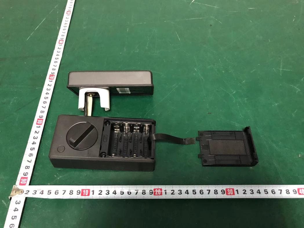
2AWPP-ASL220
Aug 03, 2024Smart Lock
Equipment Class
DTS - Digital Transmission System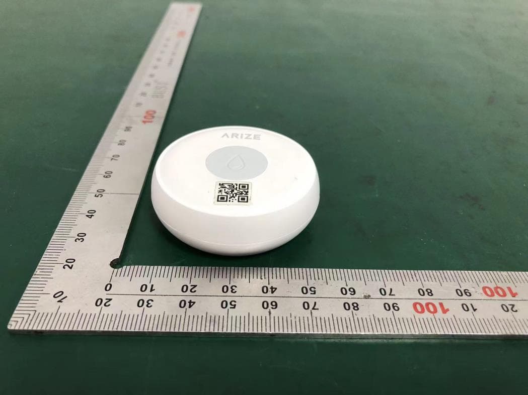
2AWPP-AWD310
Aug 02, 2024Water Detector
Equipment Class
DTS - Digital Transmission System