2AWQP-RPH20Smart Foal Foaling Alarm System Repeater
Smart Foal Pty Ltd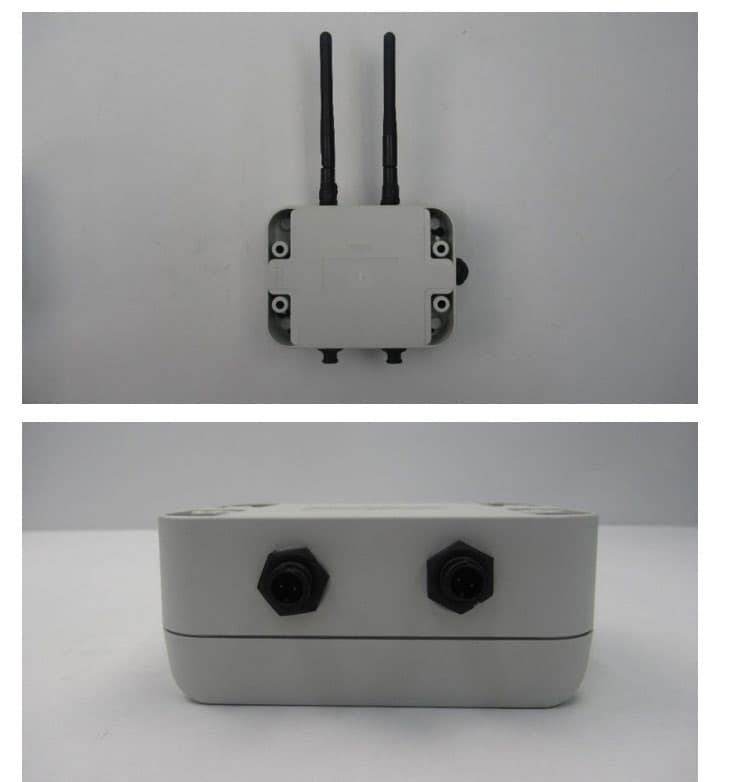
Click to zoom
Application Details
- Equipment Class
- JAB - Part 15 Class B Digital Device
- Date of Grant
- Aug 04, 2020
- Application Purpose
- Original Equipment
- Date of Application
- Aug 04, 2020
- Equipment Note
- Smart Foal Foaling Alarm System Repeater
- Company
- Smart Foal Pty Ltd
- Country
- Australia
Documents & Files
Document Text
Text extracted from the exhibit documents filed with the FCC. Open a document above to read the original.
Users Manual
Congratulations and thank you for purchasing your new Smart Foal Repeater! What’s in the box? 1 x Repeater 2 x Antenna 1 x Power pack 1 x instructions Setup: The Smart Foal Repeater is very simple to use. It is essentially plug-n-play. It’s job is to pick up signals from your mares and relay the signal back to your house/WiFi Base station. 1. Attach the antennas to the Repeater The antennas have a simple screw thread. Turn until the antenna feels firmly attached. 2 x Antennas Repeater Power pack 2. Plug in the power cord Remove the dust cap then insert the power cable. 3. Turn the Repeater on To turn on the Repeater press the switch on the side of the box. The light inside the switch will come on. 4. To turn the Repeater off, press the switch again. The light will turn off. That’s all there is to it. The Repeater will connect to, and repeat, the signal from any transmitter within range automatically. You don’t need to do anything to make it happen. Note: Both antennas should point up to the sky. The flat sides face the mares or WiFi Base station (also called a Receiver). Mare side antenna WiFi Base station side antenna Each antenna serves a purpose. The Receive Antenna (Mare side) talks to the transmitters mounted on the mares. The Transmit Antenna ONLY talks to the WiFi Base station. Position or rotate your Repeater so that the mares are mostly on the Receive Antenna side of the Repeater, and the WiFi Base station is on the Transmit Antenna side. The Repeater can be powered by the power supply in the box, a car battery or a solar panel. Depending on the connectors on your solar panel, you may be able to use the 12V battery cable to clip onto the panel directly. The solar panel must NOT exceed 32V. Minimum supply is 6V. Should you suffer a black out, or other loss of power, the internal battery will take over. The internal battery is small and will only last about 24 hours before it needs to be recharged. It’s enough for emergencies and temporary power loss, but not enough for continuous, everyday use. Siting the repeater: 1. To get the best performance place the Repeater at least 2m above the ground. Anywhere that has a good view of the mares and a moderate view of the WiFi Base station will do. 2. Place the Repeater as close as possible to the mares. You want the longest distance from the WiFi Base station to the Repeater, and a short distance from the mares to the Repeater. 3. Align your WiFi Base station so that it can “see” the Repeater. Antenna Waterproofing: If you are concerned about waterproofing the joint between the antenna and the box, run a bead of bathroom silicone around it. As the antennas ship separately to the box, we can’t do this step before it leaves our office. You could also try placing a piece of heat-shrink around the join and then shrinking it with a hair dryer. Battery care: To maintain the life of the internal battery, make sure you complete a charge/discharge cycle several times throughout the year, for example charge and discharge in January, May and September. Recharge the battery before storing. Radio Notice: FCC ID: 2AWQP-RPH20 This device complies with part 15 of the FCC Rules. Operation is subject to the following two conditions: (1) This device may not cause harmful interference, and (2) this device must accept any interference received, including interference that may cause undesired operation. This equipment has been tested and found to comply with the limits for a class B digital device, pursuant to part 15 of the FCC Rules. These limits are designed to provide reasonable protection against harmful interference in a residential installation. This equipment generates, uses and can radiate radio frequency energy and if not installed and used in accordance with the instructions, may cause harmful interference to radio communications. However, there is no guarantee that interference will not occur in a particular installation. If this equipment does cause harmful interference to radio or television reception, which can be determined by turning the equipment off and on, the user is encouraged to try to correct the interference by one or more of the following measures: * Reorient or relocate the receiving antenna. * Increase the separation between the equipment and receiver. * Connect the equipment into an outlet on a circuit different from that to which the receiver is connected. * Consult the dealer or an experienced radio/TV technician for help. This equipment has been certified to comply with the limits for a class B computing device, pursuant to FCC Rules. In order to maintain compliance with FCC regulations, shielded cables must be used with this equipment. Operation with non-approved equipment or unshielded cables is likely to result in interference to radio and TV reception. The user is cautioned that changes and modifications made to the equipment without the approval of manufacturer could void the user's authority to operate this equipment. Warranty: The Smart Foal Repeater comes with a full 12 month warranty. The internal battery has a limited 12 month warranty. Owners must meet the minimum care requirements to qualify for a free replacement. Specifications: FCC ID: 2AWQP-RPH20 Input Voltage 6 – 32V Input Current 160mA nominal Charging current 500mA Power connectors 2.1mm power jack, centre positive Antenna connectors RP-SMA female Antenna 2dBi RP-SMA male
Attestation Statements
13 July 2020 CETCB 114 Olinda Drive Brea, CA 92823 To whom it may concern: This is a letter of authorization to accept Compatible Electronics, Inc., specifically including the employees of Compatible Electronics, as an Agent for Smart Foal Pty Ltd of 40 Gard Road Mount Cottrell VIC 3024, for a period of one year, to sign applications before the Commission on our behalf, to make representations to you on our behalf, and to receive and exchange data between our company and the Commission in connection with certification of the following Smart Foal Pty Ltd product: Smart Foal Foaling Alarm system and kits including the: Smart Foal Base station, Smart Foal Repeater, Smart Foal Transmitters under FCC Docket Number 20780 and General Docket Number 80-284 pursuant to Part l5 of FCC Rules and Regulations. Please also accept this letter as an attestation that neither Smart Foal Pty Ltd nor any of its officers, directors, or persons holding 5% or more of the outstanding stock or shares, voting or non-voting, have been denied federal benefits under section 5301 of the Anti- Drug-Abuse act of 1988,21 U.S.C. 853(a). In addition, Smart Foal Pty Ltd will notify the Federal Communications Commission if, at any time, the situation changes causing Smart Foal Pty Ltd to be denied federal benefits. If you have any further questions or need additional information, please feel free to give me a call at +61 404 905 084 Sincerely, Signed by Authorized Company Officer: Aimee Nizette Managing Director
Attestation Statements
1 July 13, 2020 Compatible Electronics TCB 114 Olinda Drive Brea, California 92823 Subject: TCB application submittal To whom it may concern: We, Smart Foal Pty Ltd would like to declare that the application being submitted for the device with FCC ID: 2AWQP-RPH20, has not been submitted to another TCB or FCC for certification. If you have any questions, please do not hesitate to contact us at +61 404 905 084 Sincerely, Signed by Authorized Company Officer: Aimee Nizette Managing Director Smart Foal Pty Ltd 40 Gard Road Mount Cottrell VIC 3024 Australia
Cover Letter(s)
1 July 13, 2020 Compatible Electronics TCB 114 Olinda Drive Brea, California 92823 Subject: Request for withholding from public disclosure the schematics, block diagrams, and operational description pursuant to an application for certification To whom it may concern: We, Smart Foal Pty Ltd, would like to request that all schematics, block diagrams, and operational descriptions submitted with the application for certification be withheld from public disclosure as per Section 0.459 of FCC Rules. This request is made under the provisions of Section 0.457 (d) of the Commission’s Rules, and Section 552 (b)(4) of the Freedom of Information Act. These sections authorize the withholding from public inspection, those materials which would be privileged as a matter of law if retained by the person submitting them, and materials which would not customarily be released to the public by that person. If you have any questions, please do not hesitate to contact us at +61 404 905 084. Sincerely, Signed by Authorized Company Officer: Aimee Nizette Managing Director Smart Foal Pty Ltd 40 Gard Road Mount Cottrell VIC 3024 Australia
External Photos
FCC ID: 2AWQP-RPH20 External Photos FCC ID: 2AWQP-RPH20 External Photos FCC ID: 2AWQP-RPH20 External Photos
Internal Photos
FCC ID: 2AWQP-RPH20 Internal Photos FCC ID: 2AWQP-RPH20 Internal Photos
Test Report
Page 1 of 35 EMC Technologies Pty. Ltd. is a signatory to the ILAC Mutual Recognition Arrangement for the mutual recognition of the equivalence of testing, medical testing, calibration and inspection reports. Except for the Certificate of Compliance, this document must only be reproduced in full. EMC Technologies Pty Ltd reports apply only to the specific samples tested under stated test conditions. It is the manufacturer’s responsibility to assure that additional production units of this model are manufactured with identical electrical and mechanical components. EMC Technologies Pty Ltd shall have no liability for any deductions, inferences or generalisations drawn by the client or others from EMC Technologies Pty Ltd issued reports. This report shall not be used to claim, constitute or imply product endorsement by EMC Technologies Pty Ltd. Accredited for compliance with ISO/IEC 17025 – Testing. The results of tests, calibration and/or measurements included in this document are traceable to Australian/national standards. NATA ABN 82 057 105 549 Melbourne 176 Harrick Road Keilor Park, Vic 3042 Tel: +61 3 9365 1000 Sydney Unit 3/87 Station Road Seven Hills, NSW 2147 Tel: +61 2 9624 2777 Email: [email protected] Web: www.emctech.com.au 47 CFR PART 15, SUBPART B TEST REPORT REPORT NUMBER: M2003018-9 TEST STANDARD: 47 CFR PART 15 RADIO FREQUENCY DEVICES SUBPART B – UNINTENTIONAL RADIATORS CLIENT: SMART FOAL PTY LTD DEVICE: SMART FOAL HOME MODELS: BASE STATION: 2.0 REPEATER: 1.2 TRANSMITTER: 1.9 DATE OF ISSUE: 17 JUNE 2020 Page 2 of 35 Report No. M2003018-9 Except for the Certificate of Compliance, this document must only be reproduced in full. Equipment Under Test (EUT) Base station Transmitter Repeater REVISION TABLE Version Sec/Para Changed Change Made Date 1 Initial issue of document 17/06/2020 Page 3 of 35 Report No. M2003018-9 Except for the Certificate of Compliance, this document must only be reproduced in full. CONTENTS 1 Introduction ......................................................................................................................... 5 1.1 Test Facility ................................................................................................................ 5 1.1.1 Company Overview ............................................................................................... 5 1.1.2 NATA Accreditation ............................................................................................... 5 1.2 Test Laboratory/Accreditations .................................................................................. 6 1.3 Units of Measurements .............................................................................................. 6 1.4 Test Equipment Calibration ....................................................................................... 6 1.5 Test Configuration ..................................................................................................... 6 2 Test Procedure ................................................................................................................... 6 2.1 Summary of Test Results .......................................................................................... 6 2.2 General Information ................................................................................................... 7 2.3 Description supplied by Client ................................................................................... 7 2.4 Test sample block diagrams ...................................................................................... 8 2.5 Operating Conditions ................................................................................................. 9 2.6 Modifications .............................................................................................................. 9 3 Conducted Emissions Measurements .............................................................................. 10 3.1 Test Procedure ........................................................................................................ 10 3.2 Peak Maximising Procedure .................................................................................... 10 3.3 Calculation of Voltage Levels .................................................................................. 10 3.4 Plotting of Conducted Emission Measurement Data ............................................... 10 3.5 Test Results ............................................................................................................. 11 3.5.1 AC Mains power ports – Base Station ................................................................. 11 3.5.2 AC Mains power ports – Transmitter ................................................................... 13 3.5.3 AC Mains power ports – Repeater ....................................................................... 15 4 Radiated Emissions Measurements ................................................................................. 17 4.1 Test Procedure ........................................................................................................ 17 4.2 Plotting of Measurement Data for Radiated Emissions ........................................... 17 4.3 Calculation of Field Strength .................................................................................... 17 4.3.1 Test Results 30 – 1000 MHz ............................................................................... 18 4.3.2 Test Results Above 1 GHz Results ..................................................................... 20 5 Compliance Statement ..................................................................................................... 21 6 Measurement Uncertainty ................................................................................................ 22 Appendix A -Test Equipment ................................................................................................... 23 Appendix B - …
Text truncated - open the document above for the full version.
Test Setup Photos
Base Station FCCID: 2AQWP-BSH20 Transmitter FCC ID: 2AWQP-TXH20 Repeater FCC ID: 2AQWP-RPH20 Report No. M2003018-9 Appendix C photos Base Station FCCID: 2AQWP-BSH20 Transmitter FCC ID: 2AWQP-TXH20 Repeater FCC ID: 2AQWP-RPH20 Base Station FCCID: 2AQWP-BSH20 Transmitter FCC ID: 2AWQP-TXH20 Repeater FCC ID: 2AQWP-RPH20 Base Station FCCID: 2AQWP-BSH20 Transmitter FCC ID: 2AWQP-TXH20 Repeater FCC ID: 2AQWP-RPH20 Base Station FCCID: 2AQWP-BSH20 Transmitter FCC ID: 2AWQP-TXH20 Repeater FCC ID: 2AQWP-RPH20 Base Station FCCID: 2AQWP-BSH20 Transmitter FCC ID: 2AWQP-TXH20 Repeater FCC ID: 2AQWP-RPH20
Contact Information
Applicant
Aimee Nizette
Technical Contact
Compatible Electronics, Inc.Carla Atizado
[email protected]9495870400
20621 Pascal Way · Lake Forest, California · United States
Test Firm
EMC Technologies Pty. Ltd.Shabbir Ahmed
Technical Specifications
| # | Rule Parts | Frequency Range | Power Output |
|---|---|---|---|
| 1 | 15B | - | - |
Other Applications from Smart Foal Pty Ltd
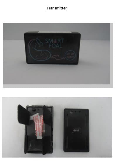
2AWQP-TXH20
Aug 04, 2020Smart Foal Foaling Alarm System Transmitter
Equipment Class
JAB - Part 15 Class B Digital Device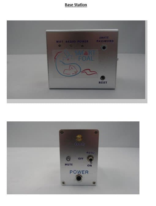
2AWQP-BSH20
Aug 04, 2020Smart Foal Foaling Alarm System Base Station
Equipment Class
JAB - Part 15 Class B Digital Device