2AWSCF4F4 noise-cancelling headphones
ShenZhen BonFin Technology CO., ltd
Click to zoom
Application Details
- Equipment Class
- DSS - Part 15 Spread Spectrum Transmitter
- Date of Grant
- Jul 06, 2020
- Application Purpose
- Original Equipment
- Date of Application
- Jul 06, 2020
- Equipment Note
- F4 noise-cancelling headphones
- Frequency Range
- 2402.00000000 - 2480.00000000
- Country
- China
Documents & Files
Document Text
Text extracted from the exhibit documents filed with the FCC. Open a document above to read the original.
Users Manual
User Manual F4 noise-cancelling headphones F4 -1- -2- -3- -4- -5- -6- -7- -8- 1. Opening the charging case will automatically turn on the earphones. The earphones will quickly emit a blue light and then enter into pairing mode. 2. Turn on your phone’s Bluetooth and look for “F4” on the device list. Tap on it to start using the earphones. Initial Usage 1. Auto-Disconnect Put the earphones inside the charging case and close the case to enter the charging mode. Bluetooth will be automatically disconnected. 2. Auto-Reconnect After the initial usage, you can subsequently use the earphonesby simply opening the charging case. The earphones will automatically reconnect to your phone even before you take it out of the case. Subsequent Usage Note: After opening the case, if the earphones are not taken out, they will turn off 5 minutes later. Before using the item for the very first time, it is recommended to place the earphones inside the case and charge them until they reach full charge. The included USB Type-C cable should be used for charging. Charging case power display Right earphone power display Charging case strike plate Left earphone power display Smart Monitoring Display of Charging Case Left earphone power display: There are 4 cells in total, each cell can hold up to 25% power, for a total of 100% when fully charged. Right earphone power display: There are 4 cells in total, each cell can hold up to 25% power, for a total of 100% when fully charged. Smart Charging 1. Earphone charging: Put the earphones inside the charging case and close the cover. They will automatically enter charging mode. Whileany of the earphones (L / R) is charging, the red light willstay on. The slots inside the charging case correspond to the earphones (L / R). At full charge, the light on the earphones will turn blue, flash for 15 seconds, then enter standby mode. 2. Charging just the Case: After inserting the charging cable into the USB Type-C slot on the case, the case will automatically start getting charged. The LED screen will display an incremental change of power from 0 to 100 during charging. 100 indicates full charge. Note: When the earphonesarebeing placed inside the charging case, this should be done smoothly with just a gentle push so as to prevent the earphones from being in poor contact with the charging probe, which may result in failure to charge. Operating the various Buttons & Keys Multi-function button, press to: play/pausemusic, answer calls,hang-up, etc. Side buttons, short press: "+"to increase volume "-" to reducevolume Side buttons, double-press: "+" to skip to next song "-" to skip to previous song Multi-function button, long press:For 3 seconds to turn offFor 6 seconds to turn on Multi-function button, double-press to: reject call, replay last song, enter Bluetooth pairing status,switch language Multi-function button, triple-press to: Activate SIRI Voice Assistant Charging the headphones Operating the Charging Case While charging, the red light will stay on. At full charge, the light will turn blue, flash for 15 seconds, then enter standby mode. Low battery alert The headphone allows you to know when the battery level is low. Whenever the remaining power is less than 10%, it will emit the following voice prompt every 20 seconds: "Low battery, please charge". Earphone status indicator ChargingRed light stays on Full chargeBlue light stays on PairingRed & blue lights flash intermittently Successful PairingRed/Blue light flashing stops Charging case indicator status Charging process, power display. Left earphone power display Charging case power display Right earphone power display 1. Using the Case to charge your phone: Connect the phone’s charging cable to USB Type-A slot on the case. The LED display will show decreasing power level on the case (from 100 going down) until the phone is fully charged and then stop 2. Charging the case: Insert the charging cable into the USB Type-C slot on the case. The LED screen will display an incremental change of power from 0 to 100 during charging. 100 indicates full charge. Attention Proper Way of Wearing the Earphones: While using the earphones, for maximum comfort, please place them on and in your ears as shown above. Specifications of earphones Specifications of earphones Dimensions: 53 * 43 * 29mm Weight: 9.0g Battery capacity: 50mAh Charging time: 2.5 hours Operating voltage: 3.3V-4.2V Standby timeout: 5 minutes (goes into standby if idle for 5mins) Music playback time: 8 hours Talk time: 8 hours Bluetooth version: 5.0 Support: Tensilica HiFi EP, Hardware FFT, SRC, Filter MCSync TWS+ Transmitter RF power: Class 3 Transmission range (Hz): 2.402-2.480GHz Communication distance: 10M Audio sampling accuracy: 16 bits Audio sampling rate: up to 96 KHz Audio encoding format: CVSD, mSBC, SBC, ACC Signal to noise ratio:> 95db Operating temperature: -15to 60 Operating humidity: 10% to 85% (non-frozen state) Specifications of earphone speakers Dimensions: Φ11mm Resistance: 16Ω + 15% copper ring moving coil SPK Frequency: 20Hz-20KHz Sensitivity: 93 ± 3dB Input power: conventional 2mW, maximum 5mW Specifications of earphone microphones Type: Silicon Microphone Sensitivity: -42 ± 1dB SPL: 130dB Safety Instructions To avoid hearing damage, keep the volume at a moderate level and avoid listening to music at high volumes for long periods of time, which may cause permanent damage to your hearing ability, including deafness. Avoid usingthe earphones while driving, cycling, crossing the road,or performing/participating in any activity that requires your full attention. Note: If you use the earphones while watching any video, audio and video may be slightly out of sync. After charging is complete, please unplug the charging cable from the charging case to avoid leaving the product in a charging state for a long time. The output voltage and current of the charger are preferably 5V, 1.0A to 1.5A. If the charger's output voltage or current exceeds the specified range, …
Text truncated - open the document above for the full version.
Cover Letter(s)
ShenZhen BonFin Technology CO., ltd 2020.6.30 Eurofins MET Labs 914 West Patapsco Avenue Baltimore, MD 21230 RE: CONFIDENTIALITY REQUEST FOR EUT NAME: F4 noise-cancelling headphones Trademark: N/A FCC ID: 2AWSCF4 MODEL : F4 To Whom It May Concern: This letter serves as an official request for confidentiality under sections 0.457 and 0.459 of CFR 47. We have requested that the - Block Diagram - Schematics - Operational Description required to be submitted with this application be permanently withheld from public review. The above materials contain trade secrets and proprietary information not customarily released to the public. The public disclosure of these materials may be harmful to the applicant and provide unjustified benefits to its competitors. Please contact me if there is any information you may need. Sincerely, Client’s signature: Client’s name / title : Jason zhou /Manager Contact information / address: South floor 5, Xinlong Science and Technology Park, 2 Wangshan 1st Road, Shajing, Baoan District, Shenzhen, China
Cover Letter(s)
ShenZhen BonFin Technology CO., ltd 2020.6.30 Eurofins MET Labs 914 West Patapsco Avenue Baltimore, MD 21230 RE: LETTER OF AGENT AUTHORIZATION To Whom It May Concern: We, the undersigned, hereby authorize Shenzhen BCTC Testing Co., Ltd to act on our behalf in all matters relating to application for equipment authorization, including the signing of all documents relating to these matters. We also hereby certify that no party to the application authorized hereunder is subject to the denial of benefits, including FCC benefits, pursuant to Section 5301 of the Anti-Drug Abuse Act of 1988, 21 U.S.C.853(a). This agreement expires one year from the current date. Sincerely, Client’s signature: Client’s name / title : Jason zhou /Manager Contact information / address: South floor 5, Xinlong Science and Technology Park, 2 Wangshan 1st Road, Shajing, Baoan District, Shenzhen, China
External Photos
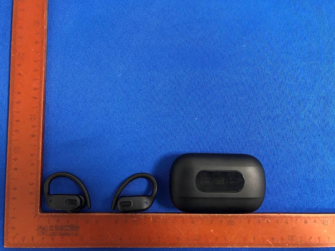
External Photos
ID Label/Location Info
10*5mm Label Location FCC ID: 2AWSCF4
Internal Photos
Internal Photos Antenna
RF Exposure Info
Shenzhen BCTC Testing Co., Ltd. FCC ID: 2AWSCF4 Portable device According to §15.247(e)(i) and §1.1307(b)(1), systems operating under the provisions of this section shall be operated in a manner that ensures that the public is not exposed to radio frequency energy level in excess of the Commission’s guidelines. According to KDB447498 D01 General RF Exposure Guidance V06 The 1-g SAR and 10-g SAR test exclusion thresholds for 100 MHz to 6 GHz at test separation distances ≤ 50 mm are determined by: [(max. power of channel, including tune-up tolerance, mW)/(min. test separation distance, mm)]·[√f(GHZ)] ≤ 3.0 for 1-g SAR and ≤ 7.5 for 10-g extremity SAR, where: • f(GHZ) is the RF channel transmit frequency in GHz • Power and distance are rounded to the nearest mW and mm before calculation • The result is rounded to one decimal place for comparison When the minimum test separation distance is < 5 mm, a distance of 5 mm is applied to determine SAR test exclusion. Modulation Channel Freq. (GHz) Conduct ed power (dBm) Conducte d power (mW) Tune-up power (dBm) Max tune-up power (dBm) Max tune-up power (mW) Distance (mm) Result calculatio n SAR Exclusion threshold SAR test exclusion GFSK2.4022.671.852±13.002.00<50.618473.00YES Pi/4 DQPSK 2.4023.332.153±14.002.51<50.778603.00YES 8DPSK2.4023.552.263±14.002.51<50.778603.00YES Conclusion: For the max result : 0.77860<3.0, the SAR testing is not required.
Test Report
Shenzhen BCTC Testing Co., Ltd. Report No.: BCTC2006000723E Test Report Tel: 400-788-9558 Web: https://www.bctc-lab.com BCTC/RF-EMC-007 Ver.:A.0 Page 1 of 70 FCC Part 15C Test Report FCC ID: 2AWSCF4 Product Name: F4 noise-cancelling headphones Trademark: N/A Model Name : F4 Prepared For : ShenZhen BonFin Technology CO., ltd Address : South floor 5, Xinlong Science and Technology Park, 2 Wangshan 1st Road, Shajing, Baoan District, Shenzhen, China Prepared By : Shenzhen BCTC Testing Co., Ltd. Address : BCTC Building & 1-2F, East of B Building, Pengzhou Industrial, Fuyuan 1st Road, Qiaotou Community, Fuyong Street, Bao’an District, Shenzhen, China Test Date: Jun. 12, 2020 – Jun. 24, 2020 Date of Report : Jun. 28, 2020 Report No.: BCTC2006000723E Shenzhen BCTC Testing Co., Ltd. Report No.: BCTC2006000723E Test Report Tel: 400-788-9558 Web: https://www.bctc-lab.com BCTC/RF-EMC-007 Ver.:A.0 Page 2 of 70 TEST RESULT CERTIFICATION Applicant’s name ............. : ShenZhen BonFin Technology CO., ltd Address .............................. : South floor 5, Xinlong Science and Technology Park, 2 Wangshan 1st Road, Shajing, Baoan District, Shenzhen, China Manufacture's Name ........ : ShenZhen BonFin Technology CO., ltd Address .............................. : South floor 5, Xinlong Science and Technology Park, 2 Wangshan 1st Road, Shajing, Baoan District, Shenzhen, China Product description Product name..................... : F4 noise-cancelling headphones Trademark ......................... : N/A Model and/or type reference F4 Standards ......................... : FCC Part15.247 ANSI C63.10:2013 This device described above has been tested by BCTC, and the test results show that the equipment under test (EUT) is in compliance with the FCC requirements. And it is applicable only to the tested sample identified in the report. This report shall not be reproduced except in full, without the written approval of BCTC, this document may be altered or revised by BCTC, personal only, and shall be noted in the revision of the document. Prepared by(Engineer): Cai Fang Zhong Reviewer(Supervisor): Eric Yang Approved(Manager): Zero Zhou Shenzhen BCTC Testing Co., Ltd. Report No.: BCTC2006000723E Test Report Tel: 400-788-9558 Web: https://www.bctc-lab.com BCTC/RF-EMC-007 Ver.:A.0 Page 3 of 70 Table of Contents Test Report Declaration Page 1. TEST SUMMARY ...................................................... 5 2. TEST FACILITY ....................................................... 6 3. MEASUREMENT UNCERTAINTY........................................ 6 4. GENERAL INFORMATION .............................................. 7 4.1 GENERAL DESCRIPTION OF EUT ....................................... 7 4.2 Test Setup Configuration ................................................ 8 4.3 Support Equipment ..................................................... 8 4.4 Channel List ........................................................... 9 4.5 Test Mode ............................................................ 10 5. TEST FACILITY AND TEST INSTRUMENT USED ........................ 11 5.1 Test Facility ........................................................... 11 5.2 Test Instrument Used .................................................. 11 6. CONDUCTED EMISSIONS ............................................. 13 6.1 Block Diagram Of Test Setup ........................................... 13 6.2 Limit ................................................................. 13 6.3 Test procedure ........................................................ 13 6.4 Test Result ........................................................... 15 7. RADIATED EMISSIONS ............................................... 17 7.1 Block Diagram Of Test Setup ........................................... 17 7.2 Limit ................................................................. 18 7.3 Test procedure ........................................................ 18 7.4 Test Result ........................................................... 20 7.5 RADIATED BAND EMISSION MEASUREMENT AND RESTRICTED BANDS OF OPERATION ........................................................... 24 8. CONDUCTED EMISSION .............................................. 27 8.1 Block Diagram Of Test Setup ........................................... 27 8.2 Limit ................................................................. 27 8.3 Test procedure ........................................................ 27 8.4 Test Result ........................................................... 28 9. 20 DB BANDWIDTH .................................................. 37 9.1 Block Diagram Of Test Setup ........................................... 37 9.2 Limit ................................................................. 37 9.3 Test procedure ........................................................ 37 9.4 Test Result ........................................................... 38 10. MAXIMUM PEAK OUTPUT POWER .................................... 43 10.1 Block Diagram Of Test Setup .......................................... 43 10.2 Limit ................................................................ 43 10.3 Test procedure ....................................................... 43 10.4 Test Result .......................................................... 44 11. HOPPING CHANNEL SEPARATION .................................... 49 11.1 Block Diagram Of Test Setup .......................................... 49 Shenzhen BCTC Testing Co., Ltd. Report No.: BCTC2006000723E Test Report Tel: 400-788-9558 Web: https://www.bctc-lab.com BCTC/RF-EMC-007 Ver.:A.0 Page 4 of 70 11.2 Limit ................................................................ 49 11.3 Test procedure ....................................................... 49 11.4 Test Result .......................................................... 50 12. NUMBER OF HOPPING FREQUENCY .................................. 55 12.1 Block Diagram Of Test Setup ...............…
Text truncated - open the document above for the full version.
Test Setup Photos
Shenzhen BCTC Testing Co., Ltd. Conducted Measurement Photos Shenzhen BCTC Testing Co., Ltd. Radiated Measurement Photos
Contact Information
Applicant
Jason zhou(Manager)
Technical Contact
Shenzhen BCTC Testing Co., Ltd.Alan Mei
[email protected]86-755-36882589
BCTC Bldg.&1-2F,East of B Bldg,Pengzhou Industrial · Baoan District, Shenzhen · China
Test Firm
Shenzhen BCTC Testing Co., Ltd.Alan Mei
[email protected]+8675536882589
Technical Specifications
| # | Rule Parts | Frequency Range | Power Output |
|---|---|---|---|
| 1 | 15C | 2.40 GHz - 2.48 GHz | 2.26 mW |
Other Applications from ShenZhen BonFin Technology CO., ltd
2AWSC-A7
Oct 08, 2024Wireless headset
Equipment Class
DSS - Part 15 Spread Spectrum Transmitter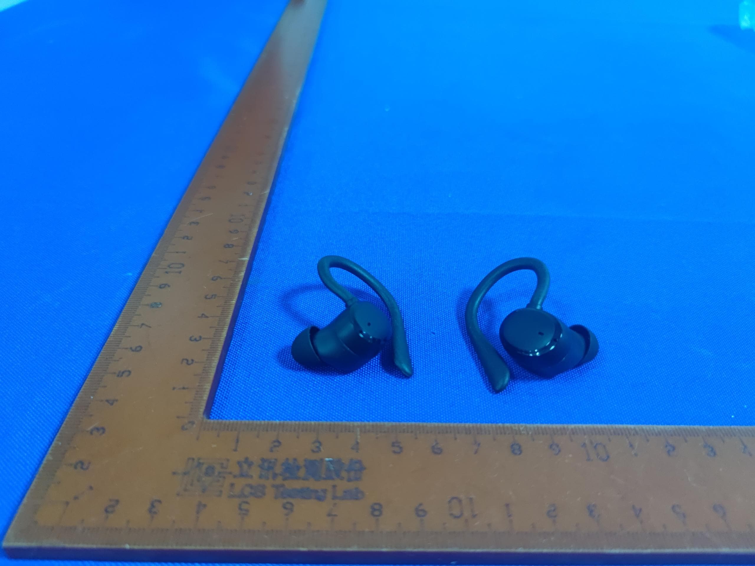
2AWSC-A12
May 18, 2024Wireless Earphones
Equipment Class
DSS - Part 15 Spread Spectrum Transmitter