2AWTJ-AFU-THY-0004Smart Temperature Box
ShenZhen AFU Intelligent Internet Technology Co.,Ltd.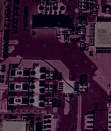
Click to zoom
Application Details
- Equipment Class
- DTS - Digital Transmission System
- Date of Grant
- Jul 09, 2020
- Application Purpose
- Original Equipment
- Date of Application
- Jul 08, 2020
- Equipment Note
- Smart Temperature Box
- Frequency Range
- 2402.00000000 - 2480.00000000
- Country
- China
Documents & Files
Document Text
Text extracted from the exhibit documents filed with the FCC. Open a document above to read the original.
Users Manual
Intelligent temperature measuring box Instruction manual AFU-THY-0004 1 Thank you for purchasing the contact safety service intelligent temperature measuring box. In order to use this product safely, please read the instruction manual before use. Please keep it properly after reading, so that you can consult it at any time. The product is powered by three 1.5V AA alkaline batteries or USB / DC5V. This product is only for testing temperature. Product description This product mainly consists of infrared probe assembly, distance sensor assembly, main circuit board assembly,LCD display assembly and shell assembly. 2 Applicable scope The temperature is displayed by the thermal radiation of the measured object. Technical indicators Normal operating conditions:ambient temperature: 15 °C ~ 35 °C Relative humidity: ≤ 85% Power supply voltage: DC 4.5V (3 AA alkaline batteries) or USB / DC5V Product ruler: 116.05mm * 86mm * 25.45mm Host weight: About 170g (without battery) Measurement range: 0 °C ~ 100 °C Accuracy: 32 °C ~ 34. 9 °C ± 0.3 °C 35°C〜 4 2°C ± 0.2°C 42.1°C〜 4 2.9°C ± 0.3°C Power consumption: ≤ 0.75w Measuring distance: 1cm ~ 15cm power off: ≤ 30 seconds Working frequency: 2400-2483mhz Emission current: 10.5mA Receiving current: 13mA Sleep current: 0.6uA Transmitting power: - 20 to + 4 DBM in 4 dB steps Receiving sensitivity: - 93 dBm 3 External dimension drawing(116.05mm*86mm*25.45mm) Special storage conditions and methods The product must be kept clean and in a dry place. Do not put the intelligent temperature measuring box on the ground with electric shock. Do not store the intelligent temperature measuring box in the extreme temperature environment of 50 °C or lower than - 20 °C, and humidity 95%. 4 Product performance Accuracy: measurement deviation ≤± 0.2 °C. Fast: measurement time 1 second. Easy to use: close to automatic detection without operation. Bluetooth: check the temperature measurement data and working status of the product at any time. Non contact: non contact measurement of material temperature. Fever alarm: set alarm temperature freely. Times of use: the key supports 100000 times. Large screen display: 4.2-inch large screen with three color backlight display, clear and readable at night. Store data: store 20 sets of measurement data. Setting modification: setting parameters can be modified. Temperature measurement conversion: multiple temperature measurement modes can be switched. Test distance: 1cm ~ 15cm. Make law The correct method is the key to test accuracy, otherwise it may cause measurement error. because The requirements of infrared temperature measurement for the surrounding environment are relatively high. Therefore, please follow the following instructions. 1. Install the battery or plug in the USB to start the machine automatically. After the display screen is fully displayed for one second, the host enters the state to be tested. When there is no object within the measurement range, it enters the standby state (automatically shut down after 30s). 2. When measuring the object temperature, when the object enters the product measurement range (15cm), the product turns on the automatic measurement. To ensure the accuracy of the measurement data, please keep the measured object still. 3. In the power on state, press the left key briefly to start a manual measurement, press the right key briefly to check the temperature measurement history, and press the left and right keys simultaneously to confirm the selection. 4. In the power on state, after connecting Bluetooth, you can check the temperature measurement data and working state of the product at any time, so as to facilitate the statistical record of the temperature measurement (for details, please see the app operation instructions). 5. When the temperature difference between the object to be 5 measured and the measured ambient temperature is lower than that of the ground to be measured, the test shall be carried out less frequently Stay in the environment for more than 5 minutes, and measure it after it is caused by the ambient temperature, otherwise it will affect the measurement result. 6. When the product is taken out from the place where the temperature difference between the product and the environment to be tested is , the product shall be placed under the environment for three minutes and then be . 7. The surrounding environment of the tested air conditioner shall be stable, and it is not allowed to test in the place where the flow of fan and air conditioner is lower than that of air conditioner. 8. Do not use the product in direct sunlight. 9. During the measurement, it is recommended to measure about 3 times each time, subject to the most significant group of data. Setting adjustment This product can modify the default setting parameters. I have done it for different sales markets before I went out It is recommended not to modify the default value of the output setting. If you need to modify it, please follow the steps below 1. In the power on state, press and hold the left key to enter the user menu, press and hold the left key again to successively enter F1 to set the buzzer switch, F2 to set the alarm temperature, F3 to set the temperature deviation correction, F4 to switch between Fahrenheit and Celsius. 2. Buzzer switch setting − F1 setting method Enter F1 buzzer switch setting mode, display "on" and horn symbol or "off" and no horn symbol on screen, press left or right key to set buzzer switch, display "on" and "off" on screen. 3. Alarm temperature setting − F2 setting method Enter F2 alarm temperature setting mode, the screen displays the preset alarm temperature, press the left or right key to increase or decrease 0.1 °C to set the customized alarm temperature. 4. Temperature correction setting − F3 setting method Enter F3 temperature correction mode to adjust the measurement deviation of the product. 1 degree. (tested before delivery, it is not recommended to change this setting) 6 5. Fahre…
Text truncated - open the document above for the full version.
External Photos
Reference N Waltek Tes http://www EXHIBI EUT View 1 EUT View 2 No.: WTX20X sting Group w.semtest.co T 2 - EUT 1 2 X06039492W (Shenzhen) m.cn T EXTER W Co., Ltd. RNAL PH HOTOGR APHS Reference N Waltek Tes http://www EUT View 3 EUT View 4 No.: WTX20X sting Group w.semtest.co 3 4 X06039492W (Shenzhen) m.cn W Co., Ltd. Reference N Waltek Tes http://www EUT View 5 EUT View 6 No.: WTX20X sting Group w.semtest.co 5 6 X06039492W (Shenzhen) m.cn W Co., Ltd.
ID Label/Location Info
Reference N Waltek Tes http://www EXHIBI Proposed Specificatio n it is visible durable to r expected lif e Proposed No.: WTX20X sting Group w.semtest.co T 1 - PRO FCC ID La ns: The label or easily acc emain fully l etime. Label Loca X06039492W (Shenzhen) m.cn ODUCT L abel Forma shall be secu cessible to th legible and in ation on EU W Co., Ltd. LABELIN at urely affixed t he user, and ntact on the UT FCC NG to a permane shall not be device in al l ID Label Lo ently attached readily detac l normal cond cation d part of the d chable. The l ditions of use device, in a lo label shall be e throughout ocation where e sufficiently t the device’s e y s
Internal Photos
Reference N Waltek Tes http://www EXHIBI EUT Housi n EUT Housi n No.: WTX20X sting Group w.semtest.co T 3 - EUT ng and Boar ng and Boar X06039492W (Shenzhen) m.cn T INTER rd View 1 rd View 2 W Co., Ltd. NAL PHO OTOGRA APHS Reference N Waltek Tes http://www EUT Housi n Solder Boa r No.: WTX20X sting Group w.semtest.co ng and Boar rd-Compone X06039492W (Shenzhen) m.cn rd View 3 ent View 1 W Co., Ltd. Reference N Waltek Tes http://www Solder Boa r Solder Boa r No.: WTX20X sting Group w.semtest.co rd-Compone rd-Compone X06039492W (Shenzhen) m.cn ent View 2 ent View 3 W Co., Ltd.
Internal Photos
Reference N Waltek Tes http://www Solder Boa r Solder Boa r No.: WTX20X sting Group w.semtest.co rd-Compone rd-Compone X06039492W (Shenzhen) m.cn ent View 4 ent View 5 W Co., Ltd. Reference N Waltek Tes http://www Solder Boa r Antenna V i No.: WTX20X sting Group w.semtest.co rd-Compone iew BLE Anten X06039492W (Shenzhen) m.cn ent View 6 nna W Co., Ltd.
RF Exposure Info
RF Exposure Requirements Product Description: Smart Temperature Box Model No.: AFU-THY-0004 FCC ID: 2AWTJ-AFU-THY-0004 According to the KDB 447498 D01 v06 section 4.3.1, for 100 MHz to 6 GHz and test separation distances ≤ 50 mm, the 1-g and 10-g SAR test exclusion thresholds are determined by the following: [(max. power of channel, including tune-up tolerance, mW)/(min. test separation distance, mm)] · [√f(GHz)] ≤ 3.0 for 1-g SAR and ≤ 7.5 for 10-g extremity SAR, where - f(GHz) is the RF channel transmit frequency in GHz - Power and distance are rounded to the nearest mW and mm before calculation17 - The result is rounded to one decimal place for comparison Calculation Result: Tx frequency range: 2402-2480MHz Min. test separation distance: 5mm Maximum Conducted Output Power: -4.68dBm Tune-Up output power: -4dBm RF channel transmit frequency: 2402MHz Result: 0.1 Limit: 3.0 The exclusion thresholds is 0.1 < 3, so the transmitter complies with the RF exposure requirements and the SAR is not required.
Test Report
Waltek Testing Group (Shenzhen) Co., Ltd. http://www.semtest.com.cn Page 1 of 33 TEST REPORT Reference No. .................... : WTX20X06039492W FCC ID ................................ : 2AWTJ-AFU-THY-0004 Applicant ........................... : ShenZhen AFU Intelligent Internet Technology Co.,Ltd. Address ............................. : 808A, No. 3101, Qianhai Road, Xinghai Mingcheng Community, Nantou Street, Nanshan District, ShenZhen Product Name ................... : Smart Temperature Box Test Model. ........................ : AFU-THY-0004 Standards .......................... : FCC Part 15.247 Date of Receipt sample .... : Jun.23, 2020 Date of Test........................ : Jun.23, 2020 to Jun.28, 2020 Date of Issue ..................... : Jun.28, 2020 Test Result ......................... : Pass Remarks: The results shown in this test report refer only to the sample(s) tested, this test report cannot be reproduced, except in full, without prior written permission of the company. The report would be invalid without specific stamp of test institute and the signatures of compiler and approver. Prepared By: Waltek Testing Group (Shenzhen) Co., Ltd. Address: 1/F., Room 101, Building 1, Hongwei Industrial Park, Liuxian 2nd Road, Block 70 Bao'an District, Shenzhen, Guangdong, China Tel.: +86-755-33663308 Fax.: +86-755-33663309 Tested by: Reviewed By: Approved & Authorized By: Mike Shi / Project Engineer Lion Cai / RF Manager Silin Chen / Manager Reference No.: WTX20X06039492W Page 2 of 33 Waltek Testing Group (Shenzhen) Co., Ltd. http://www.semtest.com.cn TABLE OF CONTENTS 1. GENERAL INFORMATION ................................................................................................................................... 4 1.1 PRODUCT DESCRIPTION FOR EQUIPMENT UNDER TEST (EUT) ............................................................................... 4 1.2 TEST STANDARDS ................................................................................................................................................... 5 1.3 TEST METHODOLOGY ............................................................................................................................................. 5 1.4 TEST FACILITY ....................................................................................................................................................... 5 1.5 EUT SETUP AND TEST MODE ................................................................................................................................. 6 1.6 MEASUREMENT UNCERTAINTY .............................................................................................................................. 6 1.7 TEST EQUIPMENT LIST AND DETAILS ..................................................................................................................... 7 2. SUMMARY OF TEST RESULTS ........................................................................................................................... 9 3. RF EXPOSURE ....................................................................................................................................................... 10 3.1 STANDARD APPLICABLE ....................................................................................................................................... 10 3.2 TEST RESULT........................................................................................................................................................ 10 4. ANTENNA REQUIREMENT ................................................................................................................................ 11 4.1 STANDARD APPLICABLE ....................................................................................................................................... 11 4.2 EVALUATION INFORMATION ................................................................................................................................ 11 5. POWER SPECTRAL DENSITY ........................................................................................................................... 12 5.1 STANDARD APPLICABLE ....................................................................................................................................... 12 5.2 TEST SETUP BLOCK DIAGRAM ............................................................................................................................. 12 5.3 TEST PROCEDURE ................................................................................................................................................. 12 5.4 SUMMARY OF TEST RESULTS/PLOTS .................................................................................................................... 12 6. DTS BANDWIDTH ................................................................................................................................................. 14 6.1 STANDARD APPLICABLE ....................................................................................................................................... 14 6.2 TEST SETUP BLOCK DIAGRAM ............................................................................................................................. 14 6.3 TEST PROCEDURE ................................................................................................................................................. 14 6.4 SUMMARY OF TEST RESULTS/PLOTS .................................................................................................................... 14 7. RF OUTPUT POWER ............................................................................................................................................ 16 7.1 STANDARD APPLICABLE ....................................................................................................................................... 16 7.2 TEST SETUP BLOCK DIAGRAM ..................................…
Text truncated - open the document above for the full version.
Test Setup Photos
Reference N Waltek Tes http://www EXHIBI Conducted Radiation E No.: WTX20X sting Group w.semtest.co T 4 - TES Emission Te Emission Tes X06039492W (Shenzhen) m.cn ST SETUP est Setup st Setup (Belo W Co., Ltd. P PHOTO ow 30MHz) OGRAPH HS Reference N Waltek Tes http://www Radiation E Radiation E No.: WTX20X sting Group w.semtest.co Emission Tes Emission Tes X06039492W (Shenzhen) m.cn st Setup (30M st Setup (1GH W Co., Ltd. MHz to 1GHz Hz to 18GHz z) z) Reference N Waltek Tes http://www Radiation E No.: WTX20X sting Group w.semtest.co Emission Tes X06039492W (Shenzhen) m.cn st Setup (Abo W Co., Ltd. ove 18GHz)
Contact Information
Applicant
sijian mi(Project Department)
Test Firm
Waltek Testing Group (Shenzhen) Co., Ltd.Jandy So
Technical Specifications
| # | Rule Parts | Frequency Range | Power Output |
|---|---|---|---|
| 1 | 15C | 2.40 GHz - 2.48 GHz | 300.00 µW |
Other Applications from ShenZhen AFU Intelligent Internet Technology Co.,Ltd.
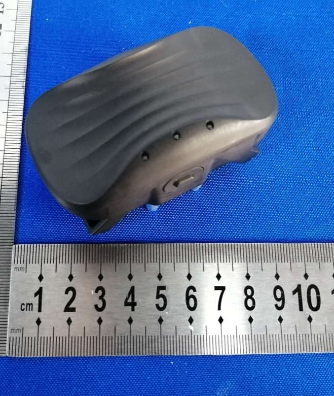
2AWTJ-AFU-WOH-0002B
Feb 07, 2021Pet training system collar unit
Equipment Class
DSC - Part 15 Security/Remote Control Transmitter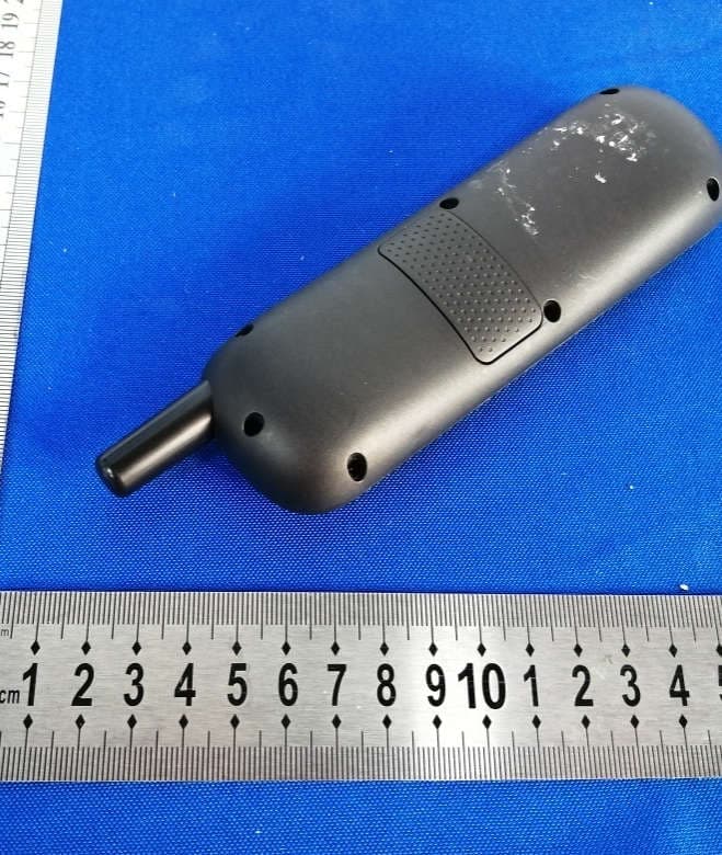
2AWTJ-AFU-WOH-0002A
Feb 07, 2021Pet training system remote control unit
Equipment Class
DSC - Part 15 Security/Remote Control Transmitter