2AWV7-C1C2C5C6E-bike
Bird Rides Inc.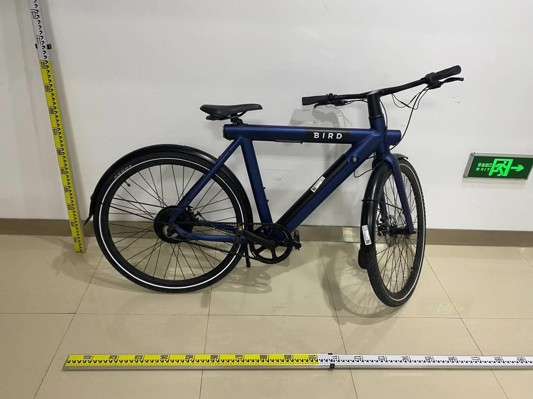
Click to zoom
Application Details
- Equipment Class
- DTS - Digital Transmission System
- Date of Grant
- Jun 07, 2022
- Application Purpose
- Original Equipment
- Date of Application
- Jun 07, 2022
- Equipment Note
- E-bike
- Frequency Range
- 2402.00000000 - 2480.00000000
- Company
- Bird Rides Inc.
- Country
- United States
Documents & Files
Document Text
Text extracted from the exhibit documents filed with the FCC. Open a document above to read the original.
Users Manual
USER MANUAL A-Frame & V-Frame User Manual Please read this manual very carefully before using the product. The manual contains important instructions for the safe use and longevity of your bike. If you need any type of support or warranty information for your BirdBike, please contact us before returning it back to wherever you purchased it. The BirdBike Support Team is ready to help you via phone or email and you can also visit support.bird.co for more info. Phone: 1-888-309-3702 (M-F 9a-5p EST) Email: [email protected] Web: support.bird.co AFRAME Pedal Crank Kickstand Front sprocket Rear disc brake Motor Rear rim Rear fender Tail light Saddle Tire AFRAME To prepare for the assembly of your BirdBike, first take out all pieces of the BirdBike from the box and remove all packaging. Also, open the accessory box and remove all tools, parts and everything else that’s inside of it. Assembly Prep1 Pedals (x 2) Wheel Reflectors (x 2) and fasteners (x 2) 2.5 mm Allen key 3mm / 4mm / 5mm Y-wrench L-key Phillips Screwdriver Rear and Front Reflectors Battery KeysPower Supply and Cable 13mm / 15mm Two-sided Wrench Cap nut and washer This Manual 4 Front light HandlebarFrame Front fender Front rim Fork Front disc brake Battery AFRAME Install the handlebar2 Remove Display from the Handlebar Use the 2.5mm Allen Key to remove the screw that’s behind the display on the handlebar. If the display isn’t easily removed from the handlebar, use the hex key to gently push it from the back of the handlebar through the hole from where the screw was removed. 2.5 mm Allen key VFRAME Y-wrench 6 Install the Handlebar Use the 5mm end of the Y-wrench to remove the hex bolt from inside the steerer tube and insert the handlebar over the steerer tube. After the handlebar is installed and lined up properly with the tire and frame, insert the hex bolt through the handlebar and into the steerer tube. Use the 5mm end of the Y-wrench to gently tighten the hex bolt into the handlebar so that there’s no play between the fork and frame. Finally, make sure the handlebar, frame, and front wheel are still aligned and tighten the two steering stem screws with the 5mm end of the Y-wrench so the handlebar stays in place. Y-wrench 3 AFRAME Attach the front fender Attach the front fender to the fork by using the screws that are already in the fork legs. Use the 4mm end of the Y-wrench to remove the two screws from the fork legs and then tighten the screws through the holes at the end of the fender mounts. Using the 4mm end of the Y-wrench remove the screw that’s on the top of the backside of the fork and tighten the screw through the fender mount bracket on top of the fender so that it’s secured tightly to the back of the fork. ack of the fork. When tightening the fender, avoid rubbing the Y-wrench on the frame so the paint doesn’t get scratched. Also, don’t over tighten the screws to avoid stripping the holes. WrenchCap Nut and Washer Install the front wheel4 Be sure to remove the plastic front rotor protector from the front wheel axle before starting this step. Align the front wheel axle so that it’s inside of the fork slots on both sides. The side with the brake rotor should be aligned so that it fits inside the front disc brake. Once the fork slots are sitting on both sides of the axle, install washers at both ends and tighten up the cap nuts on the outside using the 15mm end of the wrench. ector from the front wheel axle f the fork slots on both sides. The side t it fits inside the front disc brake. of the axle, install washers at both side using the 15mm end of the 8 After installing the front wheel, extend the kickstand for better stability and easier assembly during the next steps. Adjust the saddle5 AFRAME Remove the cap that’s covering the seat clamp screw, which is located just below the seat. Insert the seat post into the seat tube. To adjust the height, move it to where it feels comfortable, then tighten the seat clamp screw with the 5mm end of the Y-wrench. Be sure to replace the cap once the seat post is set and tightened. Warning: do not extend the seat post farther than the minimum insertion line that is indicated on the seat post. which is located just ght, move it to where with the 5mm end at post is set and Y-wrench Attach the pedals6 10 LR Install the left and right pedals by screwing them into the crank. Pay attention to which pedal is being installed on the left and the right as the left pedal is reverse threaded so it is tightened counter-clockwise. You can tell the two pedals apart by looking for the “R” on the right pedal and “L” on the left. After the pedals are screwed on by hand, use the 15mm end of the wrench to give the pedals a final tightening. PedalsWrench Install the display7 2.5 mm Allen key For the final step before powering on your BirdBike, reinstall the display back into the handlebar so that the Bird logo is at the bottom. Be sure to not pinch the cable inside of the handlebar while reinstalling. Once reinstalled, use the 2.5mm Allen key to replace and tighten the screw under the display so that it’s tightened into place inside of the handlebar. Connect the one end of the power cable coming from the bottom of the display to the other end of the power cable that is coming out of the bottom of the frame. At this point you can power on your BirdBike, but be sure to read through the rest of this manual before riding. VFRAMEVFRAME 12
Users Manual
AFRAME To prepare for the assembly of your BirdBike, first take out all pieces of the BirdBike from the box and remove all packaging. Also, open the accessory box and remove all tools, parts and everything else that’s inside of it. Assembly Prep1 Pedals (x 2) Wheel Reflectors (x 2) and fasteners (x 2) 2.5 mm Allen key 3mm / 4mm / 5mm Y-wrench L-key Phillips Screwdriver Rear and Front Reflectors Battery KeysPower Supply and Cable 13mm / 15mm Two-sided Wrench Cap nut and washer This Manual Pedal Crank Kickstand Front Sprocket Rear disc brake Motor Rear rim Rear fender Saddle Tire Tail light 14 Front light HandlebarFrame Front fender Front rim Fork Front disc brake Battery Install the handlebar2 VFRAME Remove Display from the Handlebar Use the 2.5mm Allen Key to remove the screw that’s behind the display on the handlebar. If the display isn’t easily removed from the handlebar, use the hex key to gently push it from the back of the handlebar through the hole from where the screw was removed. 2.5 mm Allen key VFRAME Install the Handlebar Use the 5mm end of the Y-wrench to remove the hex bolt from inside the steerer tube and insert the handlebar over the steerer tube. After the handlebar is installed and lined up properly with the tire and frame, insert the hex bolt through the handlebar and into the steerer tube. Use the 5mm end of the Y-wrench to gently tighten the hex bolt into the handlebar so that there’s no play between the fork and frame. Finally, make sure the handlebar, frame, and front wheel are still aligned and tighten the two steering stem screws with the 5mm end of the Y-wrench so the handlebar stays in place. Y-wrench 16 VFRAME Y-wrench 3Attach the front fender Attach the front fender to the fork by using the screws that are already in the fork legs. Use the 4mm end of the Y-wrench to remove the two screws from the fork legs and then tighten the screws through the holes at the end of the fender mounts. Using the 4mm end of the Y-wrench remove the screw that’s on the top of the backside of the fork and tighten the screw through the fender mount bracket on top of the fender so that it’s secured tightly to the back of the fork. When tightening the fender, avoid rubbing the Y-wrench on the frame so the paint doesn’t get scratched. Also, don’t over tighten the screws to avoid stripping the holes. WrenchCap Nut and Washer Install the front wheel4 Be sure to remove the plastic front rotor protector from the front wheel axle before starting this step. Align the front wheel axle so that it’s inside of the fork slots on both sides. The side with the brake rotor should be aligned so that it fits inside the front disc brake. Once the fork slots are sitting on both sides of the axle, install washers at both ends and tighten up the cap nuts on the outside using the 15mm end of the wrench. WrenchCap Nut and Washer heel otector from the front wheel axle of the fork slots on both sides. The side hat it fits inside the front disc brake. s of the axle, install washers at both utside using the 15mm end of the 18 After installing the front wheel, extend the kickstand for better stability and easier assembly during the next steps. Attach the pedals5 L R PedalsWrench Install the left and right pedals by screwing them into the crank. Pay attention to which pedal is being installed on the left and the right as the left pedal is reverse threaded so it is tightened counter-clockwise. You can tell the two pedals apart by looking for the “R” on the right pedal and “L” on the left. After the pedals are screwed on by hand, use the 15mm end of the wrench to give the pedals a final tightening. Install the display6 2.5 mm Allen key 20 For the final step before powering on your BirdBike, reinstall the display back into the handlebar so that the Bird logo is at the bottom. Be sure to not pinch the cable inside of the handlebar while reinstalling. Once reinstalled, use the 2.5mm Allen key to replace and tighten the screw under the display so that it’s tightened into place inside of the handlebar. Connect the one end of the power cable coming from the bottom of the display to the other end of the power cable that is coming out of the bottom of the frame. At this point you can power on your BirdBike, but be sure to read through the rest of this manual before riding. FUNCTIONS OVERVIEW Power button Battery capacity display Switch between mph and km/h Assist level Mileage display Speed display Walk mode Head light Error warning + button - button 22 After pressing and holding the - button for 2 seconds the BirdBike will go into Walk Mode. The display will show the push symbol and you will receive power-assistance while pushing the BirdBike in more difficult situations, like going uphill. When you release the button, Walk Mode will automatically turn off. POWER ONOFF Operating Options DISPLAY INTERFACE After long pressing the power button, the BirdBike will be turned on. While the power is on, press and hold the power button again to turn off the power. After the BirdBike is turned on, the display defaults to showing real-time speed and total distance traveled (miles or km). With a short press of the power button you can toggle through the total distance (miles/km) and single trip distance (miles/km). The power will automatically shut off after 5 minutes if not being used. WALK MODE The power-assisted Walk Mode function should only be used while pushing the electric vehicle and never used while riding. TURN ONOFF THE HEADLIGHTS Press and hold the + key for 2 seconds to turn on the headlight. When the headlight is on, the display brightness will also automatically dim. Whenever natural lighting is insufficient (such as in bad weather) or when riding in the dark, you should always turn on the headlight. Press and hold the + key again for 2 seconds to switch off the headlight. BATTERY LEVEL When the battery is full, the five-segment battery icon will be fully lit and the number of bars will decrease as the battery lev…
Text truncated - open the document above for the full version.
External Photos
Report No.: S20220422150002 1 of 2 Attachment 1: External Photo of EUT Report No.: S20220422150002 2 of 2
ID Label/Location Info
Label location
Internal Photos
Report No.: S20220422150002 1 of 3 Attachment 2: Internal Photo of EUT Report No.: S20220422150002 2 of 3 Report No.: S20220422150002 3 of 3 ANT
RF Exposure Info
FangguangInspection&TestingCo.,Ltd. Phone:+86-510-68790033 Web:www.fgtest.cn PageNumber:1of5 RFExposureEvaluationDeclaration ReportNo.:S20220422150003 IssueDate:06-01-2022 Applicant: BirdRides,Inc. Address: 406BroadwaySuite369SantaMonicaCA90401 UnitedStates FCCID:2AWV7-C1C2C5C6 ApplicationType:Certification Product:E-BIKE ModelNo.:C1,C2,C5,C6 FCCClassification:DigitalTransmissionSystem(DTS) FCCRulePart(s):Part15SubpartC(15.247) TestProcedure(s):ANSIC63.10-2013,KDB558074D01v05r02 TestDate:May01~May12,2022 CompiledBy (AmosXia) SeniorTestEngineer ApprovedBy (ZemingZhang) EngineerManager Thetestresultsrelateonlytothesamplestested. Thisequipmenthasbeenshowntobecapableofcompliancewiththeapplicabletechnicalstandardsas indicatedinthemeasurementreportandwastestedinaccordancewiththemeasurementproceduresspecified inKDB558074D01.Testresultsreportedhereinrelateonlytotheitem(s)tested. ThetestreportshallnotbereproducedexceptinfullwithoutthewrittenapprovalofFangguangInspection& TestingCo.,Ltd.WuxiBranch Thetestreportmustnotbeusedbytheclienttoclaimproductcertifications,approval,orendorsementby NVLAP,NISToranyagencyofU.S.Government. ReportNo.:S20220422150003 PageNumber:2of5 RevisionHistory ReportNo.VersionDescriptionIssueDate S20220422150003Rev.01/06-01-2022 ReportNo.:S20220422150003 PageNumber:3of5 1.PRODUCTINFORMATION 1.1.EquipmentDescription 1.2.ProductSpecificationSubjectivetothisReport ProductName:E-BIKE ModelName:C1 AdditionalModel:C2,C5,C6 ModelDescription: Allmodelsareelectricallyidentical,onlymodelnoandappearanceare different. Ratings: BikeAdapter: Input:100-240V~,50/60Hz,1.8A(MAX) Output:DC42V,2.0A Bike:DC36V Wirelessmodule:DC3.3V BluetoothVersion:5.0 BluetoothFrequency2402~2480MHz BluetoothVersion5.0 TypeofmodulationGFSK DataRate1Mbps&2Mbps AntennaType:PCBAntenna AntennaGain:0dBi ReportNo.:S20220422150003 PageNumber:4of5 2.RFExposureEvaluation 2.1.Limits AccordingtoFCC1.1310:Thecriterialistedinthefollowingtableshallbeusedtoevaluatethe environmentimpactofhumanexposuretoradiofrequency(RF)radiationasspecifiedin1.1307(b) LIMITSFORMAXIMUMPERMISSIBLEEXPOSURE(MPE) FrequencyRange (MHz) ElectricField Strength(V/m) MagneticField Strength(A/m) PowerDensity (mW/cm 2 ) AverageTime (Minutes) (A)LimitsforOccupational/ControlExposures 300-1500----f/3006 1500-100,000----56 (B)LimitsforGeneralPopulation/UncontrolledExposures 300-1500----f/15006 1500-100,000----130 f=FrequencyinMHz CalculationFormula:Pd=(Pout*G)/(4*pi*r 2 ) Where Pd=powerdensityinmW/cm 2 Pout=outputpowertoantennainmW G=gainofantennainlinearscale Pi=3.1416 r=distancebetweenobservationpointandcenteroftheradiatorincm PdisthelimitofMPE,1mW/cm².Ifweknowthemaximumgainoftheantennaandthetotalpower inputtotheantenna,throughthecalculation,wewillknowthedistancerwheretheMPElimitis reached. ReportNo.:S20220422150003 PageNumber:5of5 2.2.TestResultofRFExposureEvaluation ProductE-BIKE TestItemRFExposureEvaluation TestModeFrequencyBand (MHz) MaximumPK OutputPower (dBm) PowerDensityat R=20cm (mW/cm 2 ) Limit (mW/cm 2 ) BLE2402~24804.330.000541 Note:Pd=(Pout*G)/(4*pi*r2)=(10 (4.33+0)/10 )/(4*3.1416*20 2 )=0.00054mW/cm 2 CONCULISON: TheMaxPowerDensityatR(20cm)=0.00054mW/cm 2 <1mW/cm 2 . SotheEUTcomplieswiththerequirement. TheEnd
Test Report
FangguangInspection&TestingCo.,Ltd. HeadquartersAdd.:AreaBofthe3rdfloor,XEDASci-TechPark,XiqingEconomicDevelopmentArea,Tianjin,China Tel:+86-020-66289500-8260Email:[email protected]://www.fgtest.cn TRFNo.:FG.WI-07-Part15SubpartC(15.247)ReportsInquiry:https://grgtest.com PageNumber:1of86 ReportNo.:S20220422150002 IssueDate:06-01-2022 Applicant: BirdRides,Inc. Address: 406BroadwaySuite369SantaMonicaCA90401 UnitedStates FCCID:2AWV7-C1C2C5C6 Product:E-BIKE ModelNo.:C1,C2,C5,C6 FCCClassification:DigitalTransmissionSystem(DTS) FCCRulePart(s):Part15SubpartC(15.247) TestProcedure(s):ANSIC63.10-2013,KDB558074D01v05r02 Result:Pass TestDate:May01~May12,2022 MEASUREMENTREPORT FCCPART15.247Bluetooth-LE CompiledBy (AmosXia) SeniorTestEngineer ApprovedBy (ZemingZhang) EngineerManager Thetestresultsrelateonlytothesamplestested. Thisequipmenthasbeenshowntobecapableofcompliancewiththeapplicabletechnicalstandards asindicatedinthemeasurementreportandwastestedinaccordancewiththemeasurement proceduresspecifiedinANSIC63.4-2014.Testresultsreportedhereinrelateonlytotheitem(s)tested . ThetestreportshallnotbereproducedexceptinfullwithoutthewrittenapprovalofFangguang Inspection&TestingCo.,Ltd.WuxiBranch Thetestreportmustnotbeusedbytheclienttoclaimproductcertifications,approval,orendorsement byNVLAP,NISToranyagencyofU.S.Government. ReportNo.:S20220422150002 PageNumber: 2 of 86 RevisionHistory ReportNo.VersionDescriptionIssueDate S20220422150002Rev.01/06-01-2022 ReportNo.:S20220422150002 PageNumber: 3 of 86 CONTENTS DescriptionPage §2.1033GeneralInformation........................................................................................................................5 1.INTRODUCTION...........................................................................................................................................6 1.1.Scope...................................................................................................................................................6 1.2.FangguangTestLocation.................................................................................................................6 2.PRODUCTINFORMATION.........................................................................................................................7 2.1.EquipmentDescription......................................................................................................................7 2.2.ProductSpecificationSubjectivetothisReport............................................................................7 2.3.OperationFrequency/ChannelList...............................................................................................8 2.4.DeviceCapabilities............................................................................................................................8 2.5.DescriptionofTestSoftware............................................................................................................8 2.6.TestMode...........................................................................................................................................8 2.7.TestConfiguration.............................................................................................................................9 2.8.EMISuppressionDevice(s)/Modifications.....................................................................................9 2.9.LabelingRequirements.....................................................................................................................9 2.10.Calculationwithallconversionandcorrectionfactorsused...................................................10 3.DESCRIPTIONOFTEST..........................................................................................................................11 3.1.EvaluationProcedure......................................................................................................................11 3.2.ACLineConductedEmissions......................................................................................................11 3.3.RadiatedEmissions........................................................................................................................12 4.ANTENNAREQUIREMENTS...................................................................................................................13 5.TESTEQUIPMENTCALIBRATIONDATE............................................................................................14 6.MEASUREMENTUNCERTAINTY...........................................................................................................15 7.TESTRESULT............................................................................................................................................16 7.1.Summary...........................................................................................................................................16 7.2.6dBBandwidthMeasurement.......................................................................................................17 7.2.1.TestLimit........................................................................................................................................17 7.2.2.TestProcedureused....................................................................................................................17 7.2.3.TestSetting....................................................................................................................................17 7.2.4.TestSetup......................................................................................................................................17 7.2.5.TestResult.....................................................................................................................................18 7.3.OutputPowerMeasurement..........................................................................................................22 7.3.1.TestLimit...................................................…
Text truncated - open the document above for the full version.
Test Report
ReportNo.:S20220422150002 PageNumber: 41 of 86 BLE_BT5.0(2Mbps)_Ant1_2402_0~Reference BLE_BT5.0(2Mbps)_Ant1_2402_30~1000 ReportNo.:S20220422150002 PageNumber: 42 of 86 BLE_BT5.0(2Mbps)_Ant1_2402_1000~26500 BLE_BT5.0(2Mbps)_Ant1_2440_0~Reference ReportNo.:S20220422150002 PageNumber: 43 of 86 BLE_BT5.0(2Mbps)_Ant1_2440_30~1000 BLE_BT5.0(2Mbps)_Ant1_2440_1000~26500 ReportNo.:S20220422150002 PageNumber: 44 of 86 BLE_BT5.0(2Mbps)_Ant1_2480_0~Reference BLE_BT5.0(2Mbps)_Ant1_2480_30~1000 ReportNo.:S20220422150002 PageNumber: 45 of 86 BLE_BT5.0(2Mbps)_Ant1_2480_1000~26500 ReportNo.:S20220422150002 PageNumber: 46 of 86 7.6.RadiatedSpuriousEmissionMeasurement 7.6.1.TestLimit AlloutofbandemissionsappearinginarestrictedbandasspecifiedinSection15.205oftheTitle 47CFRmustnotexceedthelimitsshowninTableperSection15.209. FCCPart15SubpartCParagraph15.209 Frequency [MHz] FieldStrength [uV/m] MeasuredDistance [Meters] 0.009–0.4902400/F(kHz)300 0.490–1.70524000/F(kHz)30 1.705-303030 30-881003 88-2161503 216-9602003 Above9605003 7.6.2.TestProcedureUsed ANSIC63.10-2013–Section6.6.4.3 7.6.3.TestSetting PeakFieldStrengthMeasurements 1.Analyzercenterfrequencywassettothefrequencyoftheradiatedspuriousemissionof interest 2.RBW=asspecifiedinTable1 3.VBW=3MHz 4.Detector=peak 5.Sweeptime=autocouple 6.Tracemode=maxhold ReportNo.:S20220422150002 PageNumber: 47 of 86 7.Tracewasallowedtostabilize Table1-RBWasafunctionoffrequency FrequencyRBW 9~150kHz200~300Hz 0.15~30MHz9~10kHz 30~1000MHz100~120kHz >1000MHz1MHz AverageFieldStrengthMeasurements 1.Analyzercenterfrequencywassettothefrequencyoftheradiatedspuriousemissionof interest 2.RBW=1MHz 3.VBW=3MHz 4.Detector=PowerAverage(RMS) 5.Numberofsweeppoint=2001(Numberofsweeppointsmustbe≥2xspan/RBW) 6.Sweeptime=auto 7.Trace(RMS)averagingwasperformedoveratleast100traces. ReportNo.:S20220422150002 PageNumber: 48 of 86 7.6.4.TestSetup 9kHz~30MHzTestSetup: 30MHz~1GHzTestSetup: ReportNo.:S20220422150002 PageNumber: 49 of 86 1GHz~18GHzTestSetup: 18GHz~25GHzTestSetup: ReportNo.:S20220422150002 PageNumber: 50 of 86 7.6.5.TestResult TestMode:BLE(1Mbps)TestDate:2022-05-11 TestChannel:00TestEngineer:AmosXia Remark:Averagemeasurementwasnotperformedifpeaklevellowerthanaveragelimit. Otherfrequencywas20dBbelowlimitlinewithin1-18GHz,thereisnotshowinthereport. MarkFrequency (MHz) Level (dBμV) Factor (dB) Limit (dBμV/m) Margin (dB) DetectorPolarization 480057.67.397416.4PeakHorizontal 480044.157.39549.85AVHorizontal * 645547.9912.2181.8633.87PeakHorizontal 720548.2414.84545.76AVHorizontal 720557.0214.847416.98PeakHorizontal * 762050.2814.6581.8631.58PeakHorizontal 480548.217.397425.79PeakVertical * 684048.2814.1781.8633.58PeakVertical * 720552.8814.8481.8628.98PeakVertical 736050.2414.857423.76PeakVertical Note1:“*”isnotinrestrictedband,itslimitis20dBcofthefundamentalemissionlevel(101.86dBμV/m)or15.209 whichishigher. ReportNo.:S20220422150002 PageNumber: 51 of 86 TestMode:BLE(1Mbps)TestDate:2022-05-11 TestChannel:19TestEngineer:AmosXia Remark:Averagemeasurementwasnotperformedifpeaklevellowerthanaveragelimit. Otherfrequencywas20dBbelowlimitlinewithin1-18GHz,thereisnotshowinthereport. MarkFrequency (MHz) Level (dBμV) Factor (dB) Limit (dBμV/m) Margin (dB) DetectorPolarization 488056.457.477417.55PeakHorizontal 488046.987.47547.02AVHorizontal * 576546.169.8780.3234.16PeakHorizontal * 639548.0612.3280.3232.26PeakHorizontal 732056.2714.747417.73PeakHorizontal 732046.914.74547.1AVHorizontal 488047.547.477426.46PeakVertical 488038.57.475415.5AVVertical * 568546.639.6980.3233.69PeakVertical * 653048.0112.5980.3232.31PeakVertical 732055.2814.747418.72PeakVertical 732045.5414.74548.46AVVertical Note1:“*”isnotinrestrictedband,itslimitis20dBcofthefundamentalemissionlevel(100.32dBμV/m)or15.209 whichishigher. ReportNo.:S20220422150002 PageNumber: 52 of 86 TestMode:BLE(1Mbps)TestDate:2022-05-11 TestChannel:39TestEngineer:AmosXia Remark:Averagemeasurementwasnotperformedifpeaklevellowerthanaveragelimit. Otherfrequencywas20dBbelowlimitlinewithin1-18GHz,thereisnotshowinthereport. MarkFrequency (MHz) Level (dBμV) Factor (dB) Limit (dBμV/m) Margin (dB) DetectorPolarization 496055.857.587418.15PeakHorizontal 496044.727.58549.28AVHorizontal * 620047.2111.179.7932.58PeakHorizontal * 711050.1814.6479.7929.61PeakHorizontal 744054.0714.667419.93PeakHorizontal 744044.614.66549.4AVHorizontal 496046.97.587427.1PeakVertical * 620046.4311.179.7933.36PeakVertical * 642048.212.2879.7931.59PeakVertical 744054.8714.667419.13PeakVertical 744046.9114.66547.09AVVertical Note1:“*”isnotinrestrictedband,itslimitis20dBcofthefundamentalemissionlevel(99.79dBμV/m)or15.209 whichishigher. ReportNo.:S20220422150002 PageNumber: 53 of 86 TestMode:BLE(2Mbps)TestDate:2022-05-11 TestChannel:00TestEngineer:AmosXia Remark:Averagemeasurementwasnotperformedifpeaklevellowerthanaveragelimit. Otherfrequencywas20dBbelowlimitlinewithin1-18GHz,thereisnotshowinthereport. MarkFrequency (MHz) Level (dBμV) Factor (dB) Limit (dBμV/m) Margin (dB) DetectorPolarization 480057.997.397416.01PeakHorizontal 480044.617.39549.39AVHorizontal * 662548.0982.117425.91PeakHorizontal 720557.1914.847416.81PeakHorizontal 720547.8414.84546.16AVHorizontal * 741550.2682.117423.74PeakHorizontal 480049.27.397424.8PeakVertical * 684548.6482.117425.36PeakVertical * 720552.4482.117421.56PeakVertical 754050.6214.437423.38PeakVertical Note1:“*”isnotinrestrictedband,itslimitis20dBcofthefundamentalemissionlevel(102.11dBμV/m)or15.209 whichishigher. ReportNo.:S20220422150002 PageNumber: 54 of 86 TestMode:BLE(2Mbps)TestDate:2022-05-11 TestChannel:19TestEngineer:AmosXia Remark:Averagemeasurementwasnotperformedifpeaklevellowerthanaveragelimit. Otherfrequencywas20dBbelowlimitlinewithin1-18GHz,thereisnotshowinthereport. MarkFrequency (MHz) Level (dBμV) Factor (dB) Limit (dBμV/m) Margin (dB) DetectorPolarization 488056.17.477417.9PeakHorizontal 488046.637.47547.37AVHorizontal * 595046.8610.2181.3534.49PeakHorizontal * 633548.221281.3533.13PeakHorizontal 732055.5414.747418.46PeakHorizontal 732046.314.74547…
Text truncated - open the document above for the full version.
Test Setup Photos
Report No.: S20220422150002 1 of 3 Attachment 3: Test Setup Photo Description: AC Conducted Emissions Measurement Description: Radiated Emission Test Setup for 30MHz ~ 1GHz Report No.: S20220422150002 2 of 3 Description: Radiated Emission Test Setup for Above 1GHz Report No.: S20220422150002 3 of 3 Description: Conducted Test Setup Photo
Contact Information
Applicant
Brian Buccella(VP, Vehicle Strategy)
Technical Contact
Non-Technical Contact
HONGJI INTELLIGENT BIKE CO., LTDHaojun Wu
[email protected]15861579267
Test Firm
Fangguang Inspection & Testing Co. LtdZeming Zhang
[email protected]135-7047-5374
Technical Specifications
| # | Rule Parts | Frequency Range | Power Output |
|---|---|---|---|
| 1 | 15C | 2.40 GHz - 2.48 GHz | 2.71 mW |
Other Applications from Bird Rides Inc.
2AWV7-C5
Mar 21, 2022Power assisted electric bike
Equipment Class
DTS - Digital Transmission System
2AWV7029757739
Aug 23, 2020Bird Air
Equipment Class
DTS - Digital Transmission System