2AWW9-2833CCTRF Wireless CCT Dimmer
Elektra GmbH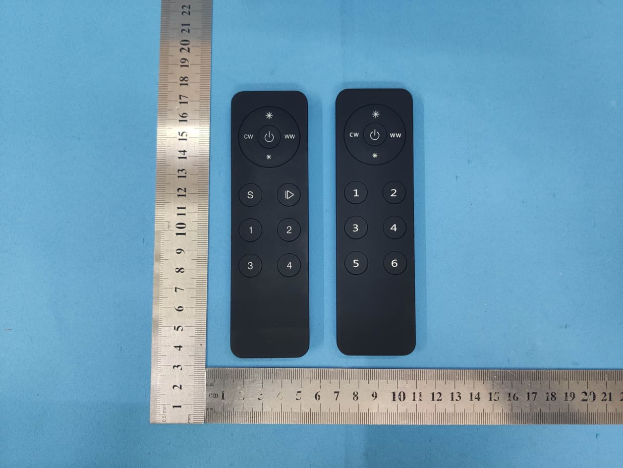
Click to zoom
Application Details
- Equipment Class
- DSC - Part 15 Security/Remote Control Transmitter
- Date of Grant
- Aug 29, 2020
- Application Purpose
- Original Equipment
- Date of Application
- Aug 29, 2020
- Equipment Note
- RF Wireless CCT Dimmer
- Frequency Range
- 869.50000000 - 869.50000000
- Company
- Elektra GmbH
- Country
- Germany
Documents & Files
Document Text
Text extracted from the exhibit documents filed with the FCC. Open a document above to read the original.
Users Manual
RF CCT Controller 70010099 Note:Before the first use, please remove the protective film on the battery. Function introduction Important: Read All Instructions Prior to Installation Output RF signal Operation Frequency 869.5MHz Operating temperature 0-40°C Relative humidity 8% to 80% Dimensions 136.3x38.9x10.7mm Front side Back side •Control 4 zones of RF receiver • Dual color controller • Compatible with universal serie RF receiver • 1 receiver can be paired by max 8 different remote controls. • Waterproof grade: IP20 Product Data •This device contains a button lithium battery that shall be stored and disposed properly. •DO NOT expose the device to moisture. Safety & Warnings Power Supply 3V(1xCR2025 battery) Control the receiver's cw channel, Press and hold down to increase/ decrease light intensity 4 zones, click to choose a zone, press and hold down to turn ON/OFF corresponding zone Control the receiver's ww channel, Press and hold down to increase/ decrease light intensity On/Off Press and hold down to increase light intensity smoothly Press and hold down to decrease light intensity smoothly Click to play/pause running mode from Warm White to Cool White Press and hold down to save color/ scene, click to recall the saved Step 3:Choose and click a zone number(e.g. zone 4) Step 2: three times continuously to set it into pairing status Click the “Learning Key” button on RF receiver or re-power on the receiver Note: one receiver can be paired with max 8 remote controls. Learning Key RF LED Receiver Step 1:Do wiring the RF receiver according to wiring diagram(please refer to the instruction of RF receiver that you would like to pair with. Step 4:Click any of the four buttons (e.g. ), LED lights connected with the RF receiver flicker once means the receiver is paired with zone 4 successfully. Pair with RF receiver Click the paired zone number/numbers, then click the other buttons to do the controlling Operate the remote after pairing SR-2833CCT If you use multiple receivers, you have two choices: Option 1: have all the receivers in the same zone, like zone 1 Learning Key RF LED Receiver Zone 1 Option 2: have each receiver in a different zone, like zone 1, 2, 3 or 4 Zone 1Zone 2Zone 3 RF remote RF remote Learning Key RF LED Receiver Learning Key RF LED Receiver Learning Key RF LED Receiver Learning Key RF LED Receiver FCC Statement This equipment has been tested and found to comply with the limits for a Class B digital device, pursuant to Part 15 of the FCC Rules. These limits are designed to provide reasonable protection against harmful interference in a residential installation. This equipment generates uses and can radiate radio frequency energy and, if not installed and used in accordance with the instructions, may cause harmful interference to radio communications. However, there is no guarantee that interference will not occur in a particular installation. If this equipment does cause harmful interference to radio or television reception, which can be determined by turning the equipment off and on, the user is encouraged to try to correct the interference by one or more of the following measures: -- Reorient or relocate the receiving antenna. -- Increase the separation between the equipment and receiver. -- Connect the equipment into an outlet on a circuit different from that to which the receiver is connected. -- Consult the dealer or an experienced radio/TV technician for help. This device complies with part 15 of the FCC Rules. Operation is subject to the following two conditions: (1) This device may not cause harmful interference, and (2) this device must accept any interference received, including interference that may cause undesired operation. Changes or modifications not expressly approved by the party responsible for compliance could void the user's authority to operate the equipment. RF CCT Controller 70010146 Note:Before the first use, please remove the protective film on the battery. Function introduction Important: Read All Instructions Prior to Installation Output RF signal Operation Frequency 869.5MHz Operating temperature 0-40°C Relative humidity 8% to 80% Dimensions 136.3x38.9x10.7mm Back side •Control 6 zones of RF receiver • Dual color controller • Compatible with universal serie RF receiver • 1 receiver can be paired by max 8 different remote controls. • Waterproof grade: IP20 Product Data •This device contains a button lithium battery that shall be stored and disposed properly. •DO NOT expose the device to moisture. Safety & Warnings Power Supply 3V(1xCR2025 battery) Step 3:Choose and click a zone number(e.g. zone 6) Step 2: three times continuously to set it into pairing status Click the “Learning Key” button on RF receiver or re-power on the receiver Note: one receiver can be paired with max 8 remote controls. Learning Key RF LED Receiver Step 1:Do wiring the RF receiver according to wiring diagram(please refer to the instruction of RF receiver that you would like to pair with. Step 4:Click any of the four buttons (e.g. ), LED lights connected with the RF receiver flicker once means the receiver is paired with zone 4 successfully. Pair with RF receiver Click the paired zone number/numbers, then click the other buttons to do the controlling Operate the remote after pairing Front side Control the receiver's CW channel, Press and hold down to increase CW and decrease WW 6 zones, click to choose a zone, press and hold down to turn ON/OFF corresponding zone Control the receiver's WW channel, Press and hold down to increase WW and decrease CW On/Off Press and hold down to increase overall brightness smoothly Press and hold down to decrease overall brightness smoothly SR-2833CCT-6Z If you use multiple receivers, you have two choices: Option 1: have all the receivers in the same zone, like zone 1 Learning Key RF LED Receiver Zone 1 Option 2: have each receiver in a different zone, like zone 1, 2, 3 or 4 Zone 1Zone 2Zone 3 RF remote RF remote Learning Key RF LED Receiver …
Text truncated - open the document above for the full version.
ID Label/Location Info
ww S 12 3 4 cw Werkstr. 7 D-32130 Enger Art.-Nr. 54015597 RF Wireless CCT Dimmer SR-2833CCTFCC ID : 2 AWW9 -2833CCT 35 mm 12 mm
RF Exposure Info
RF Exposure evaluation According to 447498 D01 General RF Exposure Guidance v05 The 1-g and 10-g SAR test exclusion thresholds for 100 MHz to 6 GHz at test separation distances≤ 50 mm are determined by: [(max. power of channel, including tune-up tolerance, mW)/(min. test separation distance, mm)] ·[√f(GHz)] ≤ 3.0 for 1-g SAR and ≤ 7.5 for 10- g extremity SAR, where f(GHz) is the RF channel transmit frequency in GHz Power and distance are rounded to the nearest mW and mm before calculation The result is rounded to one decimal place for comparison eirp = pt x gt = (EXd) 2 /30 where: pt = transmitter output power in watts, gt = numeric gain of the transmitting antenna (unitless), E = electric field strength in V/m, --- 10 ((dBuV/m)/20) /10 6 d = measurement distance in meters (m)---3m Sopt = (EXd) 2 /30 x gt Ant gain= 0 dBi ; so Ant numeric gain= 1 Field strength =81.54dBμV/m @3m So Pt={ [10 (81.54/20) /10 6 x3] 2 /30x 1}x1000 mW = 0.043 mW So (0.043 mW/5mm)x √0. 8695 GHz = 0.008 < 3 Then SAR evaluation is not required
Test Report
Global United Technology Services Co., Ltd. Report No.: GTS202006000259F01 Authorized Signature: Robinson Lo Laboratory Manager This results shown in this test report refer only to the sample(s) tested, this test report cannot be reproduced, except in full, without prior written permission of the company. The report would be invalid without specific stamp of test institute and the signatures of compiler and approver. Page 1 of 17 Cover Page TEST REPORT Applicant: Elektra GmbH Address of Applicant: Werkstrasse 7 D-32130 Enger Germany Manufacturer/Factory: Shenzhen Sunricher Technology Limited Address of Manufacturer/Factory: 3rd &4thFloor,B building,Jia'an Industrial Building,Liu Xian Third road,No.72 area,Xin'an Street, Baoan District,Shenzhen,China Equipment Under Test (EUT) Product Name: RF Wireless CCT Dimmer Model No.: Receiver: SR-2501M Transmitter: SR-2833CCT, SR-2833CCT-6Z FCC ID: 2AWW9-2833CCT Applicable standards: FCC CFR Title 47 Part 15 Subpart C Section 15.231 Date of sample receipt: June 24, 2020 Date of Test: Date of report issued: Test Result : July 03, 2020-July 06, 2020 July 07, 2020 PASS * * In the configuration tested, the EUT complied with the standards specified above. Report No.: GTS202006000259F01 Global United Technology Services Co., Ltd. No.123-128, Tower A, Jinyuan Business Building, No.2, Laodong Industrial Zone, Xixiang Road, Baoan District, Shenzhen, Guangdong, China Telephone: +86 (0) 755 2779 8480 Fax: +86 (0) 755 2779 8960 Page 2 of 17 2 Version Version No. Date Description 01 July 07, 2020 Original Prepared By: Date: July 07, 2020 Project Engineer Check By: Date: July 07, 2020 Reviewer Report No.: GTS202006000259F01 Global United Technology Services Co., Ltd. No.123-128, Tower A, Jinyuan Business Building, No.2, Laodong Industrial Zone, Xixiang Road, Baoan District, Shenzhen, Guangdong, China Telephone: +86 (0) 755 2779 8480 Fax: +86 (0) 755 2779 8960 Page 3 of 17 3 Contents Page 1 COVER PAGE .......................................................................................................................................... 1 2 VERSION .................................................................................................................................................. 2 3 CONTENTS .............................................................................................................................................. 3 4 TEST SUMMARY ..................................................................................................................................... 4 4.1 MEASUREMENT UNCERTAINTY ............................................................................................................ 4 5 GENERAL INFORMATION ...................................................................................................................... 5 5.1 GENERAL DESCRIPTION OF EUT ......................................................................................................... 5 5.2 TEST MODE ........................................................................................................................................ 6 5.3 DESCRIPTION OF SUPPORT UNITS ....................................................................................................... 6 5.4 TEST FACILITY .................................................................................................................................... 6 5.5 TEST LOCATION ................................................................................................................................. 6 5.6 OTHER INFORMATION REQUESTED BY THE CUSTOMER ......................................................................... 6 5.7 ADDITIONAL INSTRUCTIONS ................................................................................................................. 6 6 TEST INSTRUMENTS LIST ..................................................................................................................... 7 7 TEST RESULTS AND MEASUREMENT DATA ...................................................................................... 9 7.1 RADIATED EMISSION METHOD ............................................................................................................. 9 7.1.1 Field Strength of The Fundamental Signal ................................................................................ 10 7.1.2 Field Strength of The Spurious Emissions ................................................................................ 11 7.2 20DB OCCUPY BANDWIDTH .............................................................................................................. 15 7.3 DWELL TIME ..................................................................................................................................... 16 8 TEST SETUP PHOTO ............................................................................................................................ 17 9 EUT CONSTRUCTIONAL DETAILS ..................................................................................................... 17 Report No.: GTS202006000259F01 Global United Technology Services Co., Ltd. No.123-128, Tower A, Jinyuan Business Building, No.2, Laodong Industrial Zone, Xixiang Road, Baoan District, Shenzhen, Guangdong, China Telephone: +86 (0) 755 2779 8480 Fax: +86 (0) 755 2779 8960 Page 4 of 17 4 Test Summary Test Item Section in CFR 47 Result Antenna Requirement 15.203 Pass Conduction Emission 15.207 N/A Field strength of the Fundamental Signal 15.231 (b) Pass Spurious Emissions 15.231 (b)/15.209 Pass 20dB Bandwidth 15.231 (c) Pass Dwell Time 15.231 (a) (1) Pass Pass: The EUT complies with the essential requirements in the standard. N/A: Not applicable. 4.1 Measurement Uncertainty Test Item Frequency Range Measurement Uncertainty Notes Radiated Emission 30MHz-200MHz 3.8039dB (1) Radiated Emission 200MHz-1GHz 3.9679dB (1) Radiated Emission 1GHz-18GHz 4.29dB (1) Radiated Emission 18GHz-40GHz 3.30dB (1) A…
Text truncated - open the document above for the full version.
Test Setup Photos
Radiated Emission for part 15C
Contact Information
Applicant
Marius Hofmann(Approbation)
Test Firm
Global United Technology Services Co. Ltd.Robinson Lo
Technical Specifications
| # | Rule Parts | Frequency Range | Power Output |
|---|---|---|---|
| 1 | 15.231 | 869.5 MHz - 869.5 MHz | - |
Other Applications from Elektra GmbH
2AWW9RECEIVERMIX2ZB
Apr 01, 2024LED-Controller Zigbee
Equipment Class
DTS - Digital Transmission System