Text extracted from the exhibit documents filed with the FCC. Open a document above to read the original.
Introduction Setting your thermometer Function How to measure temple temperature How to measure object temperature Display LCD Data Transfer via Bluetooth Non-contact temple thermometer uses an infrared detector to detect body temperature from the temple for adult and child in the hospital, home or public place. This thermometer could also detect object tem- perature. Please read the instruction manual carefully before using the prod- uct and be sure to keep this manual. This device complies with Part 15 of the FCC Rules. Operation is subject to the following two conditions: 1) this device may not cause harmful interference and 2) this device must accept any interference received, including interfer- ence that may cause undesired operation. NOTE: This equipment has been tested and found to comply with the lim- its for a Class B digital device, pursuant to part 15 of the FCC rules. These limits are designed to provide reasonable protection against harmful in- terference in a residential installation. This equipment generates, uses and can radiate radio frequency energy and, if not installed and used in ac- cordance with the instructions, may cause harmful interference to radio communications. However, there is no guarantee that interference will not occur in a particular installation. If this equipment does cause harmful interference to radio or television reception, which can be determined by turning the equipment off and on, the user is encouraged to try to correct the interference by one or more of the following measures: 1. Reorient or relocate the receiving antenna. 2. Increase the separation between the equipment and receiver. 3. Connect the equipment into an outlet on a circuit different from that to which the receiver is connected. 4. Consult the dealer or an experienced radio/TV technician for help. 1. Open the battery cover. 2. Press “ON/OFF/Memory” button to power on the device. 3. Enter the setting mode by pressing the “ ” button to switch Temple/ Object temperature, Celsius /Fahrenheit scale, and adjust Bluetooth and beep sound in order. 4. Change the measuring target between the temple and object by pressing the “ ” button. After setting a new measuring target, the measuring site icon on the display will also be switched accordingly. 5. Change the °C and °F by pressing the “ ” button again to enter the set- ting mode. Press the “ ” button to switch the corresponding measuring scale. The measuring site icon on the display will also be switched accord- ingly after a new measuring scale is set. 6. After adjusting measuring target and scale, press the “ ” button again to move to the next setting of Bluetooth and beep sound. Temple Temperature The thermometer has been designed for practical use. It’s not meant to replace a visit to the doctor. Please also remember to compare the measurement result to your regular body temperature. Object Mode The object mode shows the actual, unadjusted surface temperatures, which is different from the body temperature. It can help you to measure any object other than body surface, for example the baby’s milk. Fever Alarm If thermometer detects a body temperature ≥37.5°C (99.5°F) there will be four beeps sound with flashing reading to warn the user for potential fever. 1. Always make sure the probe is clean, and without damage. 2. Press “ON/OFF/Memory” button to turn on the device. 3. Make sure the measuring site icon is shown on the display before taking measurement. 4. Vertically aim the thermometer at the temple with a distance of less than 10 cm. If the temple is covered with hair, sweat or dirt, remove the obstacle from the temple to improve the measuring accuracy. 5. Press the “Measuring Trigger” button to take temperature. Measurement is complete when you hear a long beep sound. 1. Press “ON/OFF/Memory” button to turn on the device. 2. Make sure the measuring site icon is shown on the display before taking measurement. 3. Once aiming at the measured target, press the “Measuring Trigger” button to take temperature. Measurement is complete when you hear a long beep sound. 4. Read the recorded temperature from the LCD display. 5. If Bluetooth has been activated, the data is automatically transferred to the App after successful completion of the binding process, please see Data Transfer via Bluetooth. Note: 1. Applications include temperature measurements for Water, Milk, Cloth, Skin or other object. 2. This mode shows the actual, unadjusted object temperatures, which is different from the body temperature. Pairing the device with your Smartphone 1. Download and install the applicable APP onto your smartphone. 2. To bind this device with your smartphone, turn on the device, Bluetooth and the App of smartphone, and follow set-up and binding instructions. 3. The Bluetooth symbol ( ) will flash on the display that indicates the binding is proceeding. - If the binding is successful, the Bluetooth symbol ( ) will illuminate on the display and the current measured temperature will automatically be transferred to the App. - If the binding has failed, the Bluetooth symbol ( ) will keep flashing until the device shuts off automatically after 1 minute, and the cur- rent measured temperature will not automatically be transferred to the App. Please rebind this device with your smartphone. Notes: 1. Unbinding your device will not delete the data from the App. 2. If you rebind your smartphone with the device, all prior reading history stored on the phone App will be retained. 3. Bluetooth data transfer will reduce the battery capacity. 4. Electromagnetic interference: The device contains sensitive electronic components. Avoid strong electrical or electromagnetic fields in the di- rect vicinity of the device (e.g. mobile telephones, microwave ovens). These may lead to temporary impairment of measurement accuracy. Non-Contact Telephoto Thermometer Model: HC700 BT Warning: Changes or modifications to this unit not expressly approved by the party responsible fo…
Text truncated - open the document above for the full version.
Telefication B.V., Dept. FCC TCB Edisonstraat 12A 6902 PK ZEVENAAR The Netherlands Telefication B.V., Dept. FCC TCB.
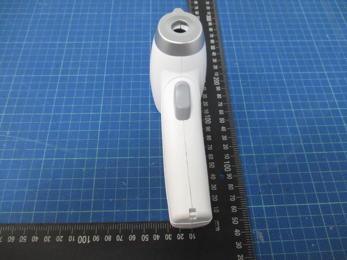
External photo of EUT External photo of EUT External photo of EUT
scale:80% scale:100% GMC Inc. No. 686, Su Chu Rd., Chuzhou, Anhui, China HC700 BT 2”AAA”Batteries 3V FCC ID: 2AWWDFH4 GMC Inc. No. 686, Su Chu Rd., Chuzhou, Anhui, China HC700 BT 2”AAA”Batteries 3V FCC ID: 2AWWDFH4
Internal photo of EUT Internal photo of EUT Internal photo of EUT
GMC Inc. TEST REPORT SCOPE OF WORK: FCC 2.1093 – RF Exposure Evaluation Report Model: HC700 BT REPORT NUMBER 201200154TWN-001 ISSUE DATE Jan. 12, 2021 PAGES 8 DOCUMENT CONTROL NUMBER GFT-OP-10h (28-Nov-2018) © 2020 Intertek Report No.: 201200154TWN-001 GFT-OP-10h (28-Nov-2018) Page 2 of 8 TEST REPORT RF Exposure Evaluation Report Applicant: GMC Inc. No. 686 Su Chu Rd., Chuzhou, Anhui, China Product: Infrared Temple Thermometer Model No.: HC700 BT FCC ID: 2AWWDFH4 Test Method/ Standard: FCC 2.1093 KDB 447498 Test By: Intertek Testing Services Taiwan Ltd., Hsinchu Laboratory No. 11, Lane 275, Ko-Nan 1 Street, Chia-Tung Li, Shiang-Shan District, Hsinchu City, Taiwan Zero Chen Engineer Durant Wei Reviewer Report No.: 201200154TWN-001 GFT-OP-10h (28-Nov-2018) Page 3 of 8 TEST REPORT Revision History Report No. Issue Date Revision Summary 201200154TWN-001 Jan. 12, 2021 Original report Report No.: 201200154TWN-001 GFT-OP-10h (28-Nov-2018) Page 4 of 8 TEST REPORT Table of Contents 1. General Information ............................................................................................................... 5 1.1 Identification of the EUT .................................................................................................. 5 1.2 Antenna description ......................................................................................................... 5 1.3 Peripherals equipment ..................................................................................................... 5 2. Test specifications ................................................................................................................... 6 2.1 RF Exposure calculations .................................................................................................. 6 2.2 Operation mode ............................................................................................................... 6 2.3 Test equipment ................................................................................................................. 6 2.4 Test Set-up ........................................................................................................................ 7 3. Test results .............................................................................................................................. 8 Report No.: 201200154TWN-001 GFT-OP-10h (28-Nov-2018) Page 5 of 8 TEST REPORT 1. General Information 1.1 Identification of the EUT Product: Infrared Temple Thermometer Model No.: HC700 BT Operating Frequency: 2402 MHz ~ 2480 MHz Channel Number: 40 channels Frequency of Each Channel: 2402+2 k, k=0 ~ 39 Rated Power: DC 3V Power Cord: N/A Sample receiving date: Oct. 04, 2019 Sample condition: Workable Test Date(s): Dec. 05, 2019 1.2 Antenna description Antenna Gain : -6.2853 dBi Antenna Type : Printed antenna Connector Type : Fixed 1.3 Peripherals equipment Peripherals Brand Model No. Serial No. Data cable Battery Panasonic LR03TTS/10S-R N/A N/A Report No.: 201200154TWN-001 GFT-OP-10h (28-Nov-2018) Page 6 of 8 TEST REPORT 2. Test specifications 2.1 RF Exposure calculations According to KDB 447498 D01 , Mobile and Portable Devices RF Exposure Procedures and Equipment Authorization Policies v06. Clause 4.3: General SAR test reduction and exclusion guidance Sub , clause 4.3.1: Standalone SAR test exclusion considerations a) The 1-g and 10-g SAR test exclusion thresholds for 100 MHz to 6GHz at test separation distance≤5 mm are determined by: [(max. power of channel, including tune-up tolerance, mW)/(min. test separation, mm)]*[√ f(GHz) ] ≤3.0 for 1-g SAR [(max. power of channel, including tune-up tolerance, mW)/(min. test separation, mm)]*[√ f(GHz) ] ≤7.5.0 for 10-g SAR 2.2 Operation mode The EUT was supplied with DC 3 V from battery. EUT press the button to select different frequency and modulation. 2.3 Test equipment Equipment Brand Model No. Serial No. Calibration Date Next Calibration Date Power Meter Anritsu ML2495A 0844001 2019/10/23 2020/10/21 Power Sensor Anritsu MA2411B 0738452 2019/10/23 2020/10/21 Report No.: 201200154TWN-001 GFT-OP-10h (28-Nov-2018) Page 7 of 8 TEST REPORT 2.4 Test Set-up Report No.: 201200154TWN-001 GFT-OP-10h (28-Nov-2018) Page 8 of 8 TEST REPORT 3. Test results Mode Frequency (GHz) Conducted Power (dBm) Distance (mm) Tune-up Tolerance Max Power (dBm) Max Power (mW) Result SAR Test Exclusion Threshold Exempt from Test? BLE 2.402-2.480 1.79 5 1 2.79 1.90 0.599 3.0 Yes
GMC Inc. TEST REPORT SCOPE OF WORK: 47 CFR FCC Part 15.247 – Radio Spectrum report Model: HC700 BT REPORT NUMBER 201200152TWN-001 ISSUE DATE Jan. 12, 2021 PAGES 33 DOCUMENT CONTROL NUMBER GFT-OP-10h (28-Nov-2018) © 2020 Intertek Report No.: 201200152TWN-001 This report is for the exclusive use of Intertek's Client and is provided pursuant to the agreement between Intertek and its Client. Intertek's responsibility and liability are limited to the terms and conditions of the agreement. Intertek assumes no liability to any party, other than to the Client in accordance with the agreement, for any loss, expense or damage occasioned by the use of this report. Only the Client is authorized to permit copying or distribution of this report and then only in its entirety. Any use of the Intertek name or one of its marks for the sale or advertisement of the tested material, product or service must first be approved in writing by Intertek. The observations and test results in this report are relevant only to the sample tested. This report by itself does not imply that the material, product, or service is or has ever been under an Intertek certification program. GFT-OP-10h (28-Nov-2018) Page 1 of 33 Test Report 0597 Radio Spectrum TEST REPORT Applicant: GMC Inc. No. 686 Su Chu Rd., Chuzhou, Anhui, China Product: Infrared Temple Thermometer Model No.: HC700 BT FCC ID: 2AWWDFH4 Test Method/ Standard: 47 CFR FCC Part 15.247 & ANSI C63.10 2013 KDB 558074 D01 v05r02 Test By: Intertek Testing Services Taiwan Ltd., Hsinchu Laboratory No. 11, Lane 275, Ko-Nan 1 Street, Chia-Tung Li, Shiang-Shan District, Hsinchu City, Taiwan Zero Chen Engineer Durant Wei Reviewer Report No.: 201200152TWN-001 GFT-OP-10h (28-Nov-2018) Page 2 of 33 TEST REPORT Revision History Report No. Issue Date Revision Summary 201200152TWN-001 Jan. 12, 2021 Original report Report No.: 201200152TWN-001 GFT-OP-10h (28-Nov-2018) Page 3 of 33 TEST REPORT Table of Contents 1. General Information ............................................................................................................... 6 1.1 Identification of the EUT .................................................................................................. 6 1.2 Antenna description ......................................................................................................... 6 1.3 Peripherals equipment ..................................................................................................... 6 1.4 Operation mode ............................................................................................................... 7 2. Minimum 6 dB Bandwidth ..................................................................................................... 8 2.1 Instrument Setting ............................................................................................................ 8 2.2 Test Procedure .................................................................................................................. 8 2.3 Test Diagram ..................................................................................................................... 8 2.4 Limit .................................................................................................................................. 8 2.5 Operating Environment Condition ................................................................................... 8 2.6 Test Results ....................................................................................................................... 9 3. Maximum Peak Conducted Output Power ........................................................................... 11 3.1 Instrument Setting .......................................................................................................... 11 3.2Test Procedure ................................................................................................................. 11 3.3 Test Diagram ................................................................................................................... 11 3.4 Limit ................................................................................................................................ 11 3.5 Operating Environment Condition ................................................................................. 11 3.6 Test Results ..................................................................................................................... 12 4. Power Spectral Density ......................................................................................................... 13 4.1 Instrument Setting .......................................................................................................... 13 4.2 Test Procedure ................................................................................................................ 13 4.3 Test Diagram ................................................................................................................... 13 4.4 Limit ................................................................................................................................ 13 4.5 Operating Environment Condition ................................................................................. 13 4.6 Test Results ..................................................................................................................... 14 5. Emissions in Non-Restricted Frequency Bands .................................................................... 16 5.1 Instruments Setting ........................................................................................................ 16 5.2 Test Procedure ................................................................................................................ 16 5.3 Test Diagram ................................................................................................................... 16 5.4 Limit ....................................................…
Text truncated - open the document above for the full version.
Radiated Emission Test set-up photo 30MHz~1GHz Radiated Emission Test set-up photo Above 1GHz
No. 11, Lane 275, Ko-Nan 1 Street, Chia-Tung Li, · Taiwan
| # | Rule Parts | Frequency Range | Power Output |
|---|---|---|---|
| 1 | 15C | 2.40 GHz - 2.48 GHz | 1.50 mW |

Blood pressure monitor
Equipment Class
DTS - Digital Transmission System
