FCCID.CO- FCC ID Database
HomeCompaniesEquipment ClassesSearch

© 2026 FCC ID Database. All rights reserved.

AboutContactData sourced from FCC public records
  1. Home/
  2. Forward Industries/
  3. 2AWWQ-KBBM1115

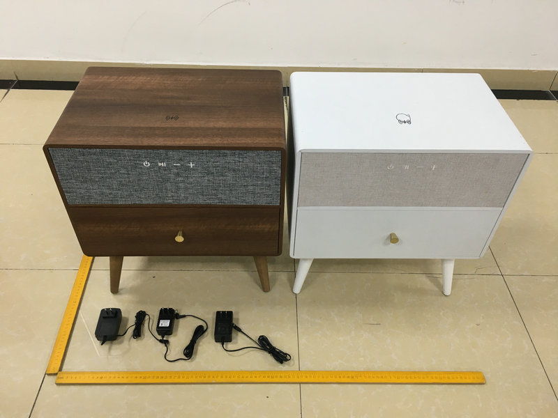
2AWWQ-KBBM1115Side Table

Forward Industries
Side Table - FCC ID 2AWWQ-KBBM1115 - Forward Industries
Click to zoom

Application Details

Equipment Class
DSS - Part 15 Spread Spectrum Transmitter
Date of Grant
Jul 30, 2020
Application Purpose
Original Equipment
Date of Application
Jul 30, 2020
Equipment Note
Side Table
Frequency Range
2402.00000000 - 2480.00000000
Company
Forward Industries
Country
United States

Documents & Files

Select a file to view
Users Manual

↗

External Photos

↗

ID Label/Location Info

↗

Internal Photos

↗

Operational Description

↗

RF Exposure Info

↗

Test Report

↗

Test Setup Photos

↗

Document Text

Text extracted from the exhibit documents filed with the FCC. Open a document above to read the original.

Users Manual

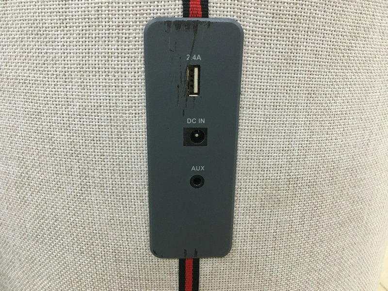
Smart Side Table PRODUCT REFS-KBBM1115 / KBBM1116/KBBM1117 Assembly Instruction Thank you for purchasing the Smart Side Table. In order to make the best use of this product and to use it safely, please read the manual carefully before use and keep it for future reference. Imported By: Forward Industries, 33401. U.S.A Issue 1-06/07/2020 ① Safety and CareAdvice 1. The maximum weight that can be placed on this product is 33 LBS. 2. This product must not be used as a seat. 3. Always use the original AC power adapter and power cable, otherwise it may cause slow wireless charging, poor bluetooth speaker function. In extreme cases, an incompatibleAC power adapter may burn out. Specifications 2.0 CH Bluetooth Table speaker Bluetooth version: 4.2 Bluetooth transmit distance: Up to 32.8 feet Bluetooth frequency: 2.402-2.480GHz Drive units: 3" 4Ω 12W x 2pcs RMS: 20W (10W*2) Working voltage: DC 12V2A Wireless Charging: 5W (5V1A) Power Supply:AC adapter ,100-240V ~ 50 / 60Hz Function Bluetooth Hands free Wireless charger function TWS function ( true wireless stereo ) ② Main Components Main Body Qty 1 (19*12.6*13 inch) Legs Qty 4 ( 6.7 inch ) Legs Qty 4 ( 10 inch ) Note : two size legs options supplied Accessories PowerAdapter Qty 1 (59 inch ) EVApad Spare Parts(If required) Qty 4 (1.18 inch) ③ Assembly Steps Step 1 Place main body upside down on to a clean fat surface. Note:Ensure the surface is suitably protected to prevent any scratches or damage to the main body . Screw legsinto position on the underside of main body. Note:Two different legs length options are supplied. ④ Step 2 With help, carefully turn the side table over into the standing position. Step 3 Plug the power adapter into the ‘DC IN’ port on the back of main body. Plug the adapter into an electric socket for mains power. ⑤ Controls / Functions FrontBackTop 1. POWER / TWS 2. PLAY / PAUSE / PHONE 3. VOLUME - 4. VOLUME + 5. MIC 6. BLUETOOTH MODE LED INDICATOR 7. TWS MODE LED INDICATOR 8. DC IN 9. WIRELESS CHARGING SYMBOL ⑥ Power On / Off 1. Connect the power adapter with the DC IN port (please make sure you use the original adapter supplied). You will hear "Power on" from the speaker. The speaker will automatically enter Bluetooth mode as default, and you will hear "Bluetooth, waiting for connection". 2. Press and hold the [] button to turn the unit off. You will hear "Power off". 3. Press and hold the [] button to turn the unit back on. Bluetooth Connection and Play ( LED indicator: the left LED light ) 1. With the power on and the unit in Bluetooth mode, it will automatically switch to pairing state. The blue LED light will flash slowly. The Bluetooth device name is ‘KBBM Side Table’. 2. Aphone or other device can now be paired with the unit. 3. You will hear "Bluetooth is Connected" after pairing. The blue LED light will become constant. If pairing fails, the blue LED light will flash quickly. 4. During music playback, the music can be paused by short pressing the 【】 button. It will play again after a further short press of the 【】 button. 5. When this unit is connected to a smart phone, press and hold the 【】 button to switch off the Bluetooth connection. You will hear "Bluetooth disconnected, waiting for connection". 6. Another device can be connected by repeating paring with Ralph. It is not possible to have two devices connected simultaneously. 7. The best distance between smart phone and speaker is ≤ 32.8 feet. Volume control 1. Press the 【 ➕ 】 button to increase the volume. The speaker will automatically defaults to mid volume when switched on. You will hear the voice prompt“ Maximum volume”when volume is max. Meanwhile, please increase the volume of the phone to maximum. 2. Press the 【 ➖ 】 button to decrease the volume. Phone calls when connected 1. If you receive a call whilst your Phone is connected via Bluetooth, the speaker will sound your ring tone. Short press the 【】 button to answer the phone and speak to the MIC. Short press the 【】 button again to hang up, or long press to decline the call. 2. Double press the 【】 button to redial the phone number of the last call. Wireless Charging 1. If you have a mobile device with wireless charging capability, it can be charged by placing it on the wireless charging symbol on the top of the unit. 2. Make sure that the smart phone is within the charging area. Once charging begins, the charging signal will be show on the phone screen. You can remove your smart phone form the charging area at any time to end the charging process. 3. The wireless charger will charge compatible mobile devices even when the unit is turned off, providing the ⑦ AC adapter is connected, to a mains power source that is switched on. 4. Some phone cases may inhibit the wireless charging function. It may be necessary to remove the phone cases to improve wireless charging efficiency. TWS Function ( LED indicator: the right LED light ) 1. If you have two side tables, you can listen to music in TWS mode via Bluetooth. Turn on both tables. Double click the 【】 button of one speaker. The speaker will enter TWS paring mode. Your will hear an acoustic signal and the orange LED indicator flash rapidly. After TWS pairing, the orange LED of main speaker will become constant, and the LED of sub-speaker will flash slowly. 2. To switch off TWS pairing, press the 【】 button of one speaker. Automatic Power Off The speaker will automatically turn off, if none of it’s functions are used after 10 minutes. Disposal If disposal of this product becomes necessary, please do this in an environmentally responsible way. Contact your local government office or authority for suitable disposal or recycling options in your local area. Do not dispose of this product, or it’s components, with your general domestic waste. FCC STATEMENT : This device complies with Part 15 of the FCC Rules. Operation is subject to the following two conditions: (1) This device may not cause harmful interference, and (2) This device must accept any interference receiv…

Text truncated - open the document above for the full version.

External Photos

FCC ID: 2AWWQ-KBBM1115

ID Label/Location Info

Label Location On EUT Label Product Name: Side Table Model No.: KBBM1115 FCC ID: 2AWWQ-KBBM1115 This device complies with Part 15 of the FCC Rules. Operation is subject to the following two conditions: (1) This device may not cause harmful interference, and (2) This device must accept any interference received, including interference that may cause undesired operation.

Internal Photos

FCC ID: 2AWWQ-KBBM1115 BTANT Wireless chargerANT

Operational Description

version01 Forward Industries Declaration concerning Antenna Specification It is hereby declared that the product Model No.: KBBM1115, KBBM1116, KBBM1117 FCC ID : 2AWWQ-KBBM1115 fulfills the requirement in FCC test relating to the antenna type. The device specified above confirms to the FCC recommendations for internal antenna type(s) described below: BDR&EDR Model No. of antenna: N/A Type of antenna: PCB Antenna Gain of the antenna: 0.5 dBi Frequency range: 2402-2480MHz Wireless charger: Model No. of antenna: KBBM1115 Type of antenna: Inductive loop coil Antenna Antenna Gain of the antenna: 0 dBi Frequency range: 110.1-205KHz The mounting of the antenna is fixed to the radio module and no other antenna should be used. Company name: Forward Industries Address: 105 South Narcissus Avenue, Suite 412, West Palm Beach, FL 33401, USA City:West Palm Beach ZIP / Postal code: 33401 Country:United Kingdom Place:United KingdomDate: 2020-07-28 Signature:

RF Exposure Info

RF EXPOSURE EVALUATION FCC ID: 2AWWQ-KBBM1115 According to FCC 1.1310: The criteria listed in the following table shall be used to evaluate the environment impact of human exposure to radio frequency(RF) Radiation as specified in §1.1307(b): Routine SAR evaluation refers to that specifically required by §2.1093, using measurements or computer simulation. When routine SAR evaluation is not required, portable transmitters withoutput power greater than the applicable low threshold require SAR evaluation to qualify for TCB approval. Channel (MHz) Maximum output power (dBm) Tune up tolerance (dBm) Max Tune Up Power (dBm) Distance (mm) Calculation results Limit Operating Mode 2402-2.073 -2.073±1 -1.07350.2423 BDR+EDR 2441-2.320 -2.320±1-1.32050.2313 2480-2.748 -2.748±1 -1.74850.2113 24020.673 0.673±1 1.67350.4563 24410.544 0.544±11.54450.4463 24800.261 0.261±1 1.26150.4213 Test Results:PASS.

Test Report

Report No.: 18220WC00088501FCC ID: 2AWWQ-KBBM1115Page 1 of 74 Code:AB-RF-05-a FCC TEST REPORT Client Name: Forward Industries Address: 105 South Narcissus Avenue, Suite 412, West Palm Beach, FL 33401, USA Product Name: Side Table Date: Jul. 28, 2020 Shenzhen Anbotek Compliance Laboratory Limited Report No.: 18220WC00088501FCC ID: 2AWWQ-KBBM1115Page 2 of 74 Code:AB-RF-05-a Contents 1. General Information ............................................................................................................................................... 5 1.1. Client Information ....................................................................................................................................... 5 1.2. Description of Device (EUT) ..................................................................................................................... 5 1.3. Auxiliary Equipment Used During Test ................................................................................................... 6 1.4. Description of Test Modes ........................................................................................................................ 6 1.5. List of channels ........................................................................................................................................... 7 1.6. Description Of Test Setup ......................................................................................................................... 8 1.7. Test Equipment List .................................................................................................................................... 9 1.8. Measurement Uncertainty ....................................................................................................................... 10 1.9. Description of Test Facility ...................................................................................................................... 10 2. Summary of Test Results ................................................................................................................................... 11 3. Conducted Emission Test ................................................................................................................................... 12 3.1. Test Standard and Limit .......................................................................................................................... 12 3.2. Test Setup .................................................................................................................................................. 12 3.3. Test Procedure .......................................................................................................................................... 12 3.4. Test Data .................................................................................................................................................... 12 4. Radiation Spurious Emission and Band Edge ................................................................................................ 25 4.1. Test Standard and Limit .......................................................................................................................... 25 4.2. Test Setup .................................................................................................................................................. 25 4.3. Test Procedure .......................................................................................................................................... 26 4.4. Test Data .................................................................................................................................................... 27 5. Maximum Peak Output Power Test .................................................................................................................. 39 5.1. Test Standard and Limit .......................................................................................................................... 39 5.2. Test Setup .................................................................................................................................................. 39 5.3. Test Procedure .......................................................................................................................................... 39 5.4. Test Data .................................................................................................................................................... 39 6. 20DB Occupy Bandwidth Test ........................................................................................................................... 43 6.1. Test Standard ............................................................................................................................................ 43 6.2. Test Setup .................................................................................................................................................. 43 6.3. Test Procedure .......................................................................................................................................... 43 6.4. Test Data .................................................................................................................................................... 43 7. Carrier Frequency Separation Test ................................................................................................................... 47 7.1. Test Standard and Limit .......................................................................................................................... 47 7.2. Test Setup .................................................................................................................................................. 47 7.3. Test Procedure .......................................................................................................................................... 47 7.4. Test Data .......…

Text truncated - open the document above for the full version.

Test Setup Photos

FCC ID: 2AWWQ-KBBM1115 Photo of Conducted Emission Measurement Photo of Radiation Emission Test Photo of MPE Measurement

Contact Information

Applicant

Andrew Ball(Head of Quality and Compliance)
[email protected]561 465 0030Fax: N.A.

Test Firm

Shenzhen Anbotek Compliance Laboratory LimitedJeff Zhu
[email protected]86-755-26064492Fax: 86-755-26014772

Technical Specifications

#Rule PartsFrequency RangePower Output
115C2.40 GHz - 2.48 GHz1.20 mW
Confidentiality
Long Term
Grant Notes
Power listed is conducted.

Other Applications from Forward Industries

Side Table - FCC ID 2AWWQ-KBBM1111 - Forward Industries
2AWWQ-KBBM1111

Side Table

Jul 31, 2020

Equipment Class

DCD - Part 15 Low Power Transmitter Below 1705 kHz