2AX2O-280010319AE WIRELESS TEMPERATURE SENSOR
28 Gorilla
Click to zoom
Application Details
- Equipment Class
- DTS - Digital Transmission System
- Date of Grant
- Jul 11, 2021
- Application Purpose
- Original Equipment
- Date of Application
- Jul 11, 2021
- Equipment Note
- AE WIRELESS TEMPERATURE SENSOR
- Frequency Range
- 2402.00000000 - 2480.00000000
- Company
- 28 Gorilla
- Country
- United States
Documents & Files
Document Text
Text extracted from the exhibit documents filed with the FCC. Open a document above to read the original.
Users Manual
AE Wireless Temperature Sensor Version 1.0.0 - 4/22/2021 Product Overview Items Included: 1. 1 - AE Wireless charging station (WCS) 2. 4 - AE Wireless Temperature Sensors (WTS) 3. 1 - AC Adapter 4. 1 - USB-A to USB-C charging cable. The AE Wireless Temperature Sensor contains an infrared temperature sensor which is used to measure and record the temperature of a surface. A User is able to place the device against a desired surface and continuously monitor the temperature of the location. The sensor is able to record and wirelessly transmit the temperature data to a mobile device. Notes In order for the User to access the information transmitted by the Wireless Temperature Sensor (WTS), there is an accompanying AE mobile application that must be downloaded and used on a mobile device. The mobile application allows the user to interface with the WTF and access WTS’s internal information wirelessly. Operational Modes The AE Wireless Temperature Sensor (WTS) contains two operational modes, and one sleep mode. The first operational mode is charging, where the device is not performing temperature measurements and is focused on charging the internal battery. While the WTS is charging, it will limit wirelessly accessible data to the state of charge of the battery and charge status. This is reflected in the mobile application where the user is able to see the status of the battery while temperature information is removed from view. The second mode is normal operation mode. In this mode the WTS discharges from the internal battery and performs periodic temperature readings from the surface directly in front of the infrared temperature sensor. The data is collected and wirelessly transmitted to a mobile device. During this operational mode the User is able to view within a mobile application, battery status information and periodic temperature information. The last operational mode is sleep mode. In the event the internal battery is discharged to a critical level. The sensor will enter a sleep mode and will be unable to be detected or connected to wirelessly. It is recommended when the device enters this sleep state that the User places the device on the charger within 24 hours, in order to recharge the sensor’s internal battery. Charging ***It is recommended to fully charge the device before first time use.*** ***If the WTS is not positioned correctly within the charging station, it will not charge.*** In order to charge the WTS units, the User must: 1. Plug the AC wall adapter into a powered wall socket. 2. Connect the USB cable into the AC wall adapter (USB-A) and into the wireless charging station. a. The User should see the wireless charging station’s indicator led illuminate within 10 seconds of power on. 3. Place the WTS units in their proper orientation on the wireless charging station. WTS Placement After the wireless charging station is powered on. The user may place the Wireless Temperature Sensors WTS in any order onto the wireless charging station. The WTS and wireless charging station are keyed in order to indicate the proper placement of the WTS within the wireless charging station. The WTS should be placed correctly within the slots with the notched grove on the bottom and closest to the outside edge of the wireless charging station. Allow the WTS to lie flat within the slots of the wireless charging station. If the WTS is not flat when placed onto the wireless charging station the user must remove the WTS and replace the WTS within the wireless charging station correctly in order for the WTS to charge. If a WTS is not positioned correctly within the wireless charging station it will not charge. Charging Notes First time charge may take up to 24 hours. It is recommended to fully charge the WTS before first time use by leaving the WTS within the charger for 24 hours. User is able to read the battery state of charge and charge status through the mobile application. After first charge, normal charge times may range between 10 to 12 hours when the WTS begins charge with a partially drained internal battery. It is recommended to allow the device to fully charge before use. However, the device may be used without reaching the fully charged state. The User in this case may see degraded performance in the WTS operational time in normal operational mode. Once charge is completed the user must leave the WTS units in a powered wireless charging station until needed for use. As the removal from the wireless charging station will trigger the WTS to exit the charge mode and enter normal operation which will discharge the battery. Normal Operation In order to activate normal operation the User must simply remove the WTS from an active charger. After 5 to 10 seconds, the WTS will exit charge mode and enter normal operation. Using the mobile application the User is able to view the operational transition of the device as the temperature reading will be displayed. The temperature reading displayed to the User will periodically update with the temperature data recorded of the surface in front of the infrared temperature sensor. The WTS may be held in place on a surface using tape or fabric as long as it does not hinder the WTS ability to transmit data wirelessly. FCC Notification Note: This equipment has been tested and found to comply with the limits for a Class B digital device, pursuant to part 15 of the FCC Rules. These limits are designed to provide reasonable protection against harmful interference in a residential installation. This equipment generates, uses and can radiate radio frequency energy and, if not installed and used in accordance with the instructions, may cause harmful interference to radio communications. However, there is no guarantee that interference will not occur in a particular installation. If this equipment does cause harmful interference to radio or television reception, which can be determined by turning the equipment off and on, the user is encouraged to try to correct t…
Text truncated - open the document above for the full version.
Cover Letter(s)
Page 1 of 2 Date: 12-2-2020 UL Verification Services Inc. 47173 Benicia Street Fremont, CA 94538, USA To whom it may concern: I, the undersigned, hereby authorize UL Verification Services Inc. to act on our behalf in all manners relating to application for equipment authorization, including signing of all documents relating to these matters. Any and all acts carried out by UL Verification Services Inc. on our behalf shall have the same effect as acts of our own. I, the undersigned, hereby certify that we are not subject to a denial of federal benefits, that includes FCC benefits, pursuant to Section 5301 of the Anti-Drug Abuse Act of 1988, 21 U.S.C. 853(a). In authorizing UL Verification Services Inc. as our representative, we still recognize that we are responsible to: a) comply with the relevant provisions of the certification program; b) make all necessary arrangements for the conduct of the evaluation, including provision for examining documentation and access to all areas, records (including internal audit reports) and personnel for the purposes of evaluation (e.g. testing, inspection, assessment, surveillance, reassessment) and resolution of complaints; c) make claims regarding certification only in respect of the scope for which certification has been granted; d) do not use our product certification in such a manner as to bring the Certification Division into disrepute and not make any statement regarding our product certification which the Certification Division may consider misleading or unauthorized; e) upon suspension or cancellation of certification, discontinue use of all advertising matter that contains any reference thereto and return any certification documents as required by the Certification Division; f) use certification only to indicate the products are certified as being in conformity with specified standards; 28 Gorilla, LLC 12 S San Marco Pl Chandler, AZ 85255 www.28gorilla.com Page 2 of 2 g) endeavor to ensure that no certificate or report nor any part thereof is used in a misleading manner; h) ensure that any reference to our product certification in communication media such as documents, brochures or advertising, complies with the requirements of the Certification Division; i) keep a record of all complaints made known to the us relating to the product’s compliance with requirements of the relevant standard and to make these records available to the when requested; j) take appropriate action with respect to such complaints and any deficiencies found in products or services that affect compliance with the requirements for certification; k) document the actions taken. This authorization is valid until further written notice from the applicant. Sincerely Yours, Andy Phillips Principal / Founder
Cover Letter(s)
Page 1 of 2 Date: 12- 2-2020 Federal Communications Commission 7435 Oakland Mills Road Columbia MD 21046 Subject: Request for Confidentiality FCC ID: 2AX2O–280010319 To Whom It May Concern: Pursuant to the provisions of Sections 0.457 and 0.459 of the Commission’s rules (47 CFR §§ 0.457, 0.459), we are requesting the Commission to withhold the following attachments as confidential document from public disclosure indefinitely. Schematic Diagram Block Diagram Theory of Operation Antenna Specification Above mentioned document contains detailed system and equipment description are considered as proprietary information in operati on of t he equipment. The public disclosure of a bove documents might be harmful to our company and woul d give competitor an unfair advantage in the market. In a dditional to above m entioned documents, pursuant to Public N otice D A 0 4-1705 of the C omm ission’s policy, in order to comply with the marketing regulations in 47 CFR §2.803 and the importation rul es in 47 CFR §2.1204, whil e ensuri ng that business sensiti ve information remai ns confidential until the actual marketi ng of newl y authorized devices . We are requesting the commission to grant short-t erm confidentiality request on the following attachments until Dec 15th, 2021: External Photos Internal Photos Test Setup Photos User Manual It is o ur understanding that all m easurement test reports, FCC ID label format and correspondent duri ng c ertific ati on review process cannot be grant ed as confidential 28 Gorilla, LLC 12 S San Marco Pl Chandler, AZ 85255 www.28gorilla.com Page 2 of 2 documents and those information will be available for public review once the grant of equipment authorization is issued. Best Regards Andy Phillips Principal / Founder
External Photos
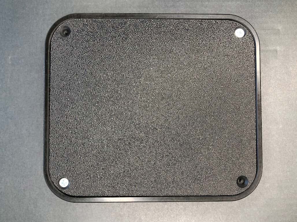
Model: 28-0010038 External Photos Top View Bottom View Model: 28-0010038 External Photos Front View Rear View Model: 28-0010038 External Photos Left Side View Right Side View
ID Label/Location Info
Page 1 of 1 Label FCC ID: 2AX2O–280010319 28 Gorilla, LLC 12 S San Marco Pl Chandler, AZ 85255 www.28gorilla.com
Internal Photos
Model: 28-0010038 Internal Photos PCB Top View PCB Bottom View Model: 28-0010038 Internal Photos WPT Antenna View
RF Exposure Info
FCC ID: 2AX2O-280010319 BTLE RF EXPOSURE EVALUATION Approved by: Quality Manager Document S/N: Evaluation Date: EUT Type: Page 1 of 1 1C2101120008-06.2AX2O 01/24/2021 AE Wireless Temperature Sensor © 2021 PCTEST. REV 21.4 M 09/11/2019 © 2021 PCTEST. All rights reserved. Unless otherwise specified, no part of this report may be reproduced or utilized in any part, form or by any means, electronic or mechanical, including photocopying and microfilm, without permission in writing from PCTEST. If you have any questions about this international copyright or have an enquiry about obtaining additional rights to this report or assembly of contents thereof, please contact [email protected]. Applicant Name: Date of Evaluation: 28 Gorilla, LLC. 01/24/2021 12 S San Marco PI Test Site/Location: Chandler, AZ 85255 PCTEST. Morgan Hill, CA, USA United States Document Serial No.: 1C2101120008-06.2AX2O F C C I D : 2AX2O-280010319 A P P L I C A N T : 28 GORIL LA, LL C. Model: 28-0010038 EUT Type: AE Wireless Temperature Sensor Application Type: Certification FCC Rule Part(s): CFR §2.1093 BTLE Overview RF Exposure Test Exclusion Per FCC KDB 447498 D01v06, the 1g SAR exclusion threshold for distances <50mm is defined by the following equation: Based on the maximum allowed conducted power of Bluetooth LE declared by the manufacturer (rounded to the nearest mW) and the antenna to user separation distance, 1g SAR was not required; [(1/5)*√2.480] = 0.315 < 3.0. Channels Operating Frequency Range [MHz] 0-39 2402-2480 Maximum Allowed Conducted Power declared by the Manufacturer BTLE Information Operating Frequency and Channels 0.597 [mW] PCTEST 18855 Adams Ct, Morgan Hill, CA 95037 USA Tel. +1.410.290.6652 / Fax +1.410.290.6654 http://www.pctest.com BTLE RF EXPOSURE EVALUATION
Test Report
FCC ID: 2AX2O–280010319 MEASUREMENT REPORT (CERTIFICATION) Approved by: Quality Manager Test Report S/N: Test Dates: EUT Type: Page 1 of 51 1C2101120008-01-R2.2AX2O 1/12/2021-1/24/2021 AE Wireless Temperature Sensor © 2021 PCTEST V 10.2 04/22/2020 All rights reserved. Unless otherwise specified, no part of this report may be reproduced or utilized in any part, form or by any means, electronic or mechanical, including photocopying and microfilm, without permission in writing from PCTEST. If you have any questions about this international copyright or have an enquiry about obtaining additional rights to this report or assembly of contents thereof, please contact [email protected]. Applicant Name: 28 Gorilla, LLC. 12 S San Marco Pl Chandler, AZ 85255 United States Date of Testing: 1/12/2021-1/24/2021 Test Site/Location: PCTEST Lab. Morgan Hill, CA, USA Test Report Serial No.: 1C2101120008-01-R2.2AX2O FCC ID: 2AX2O–280010319 APPLICANT: 28 Gorilla, LLC. Model: 28-0010038 EUT Type: AE Wireless Temperature Sensor Max. RF Output Power: 0.597mW (-2.24dBm) Peak Conducted Frequency Range: 2402 – 2480MHz FCC Classification: Digital Transmission System (DTS) FCC Rule Parts: Part 15 Subpart C (15.247) Test Procedure(s): ANSI C63.10-2013, KDB 558074 D01 v05r02 This equipment has been shown to be capable of compliance with the applicable technical standards as indicated in the measurement report and was tested in accordance with the measurement procedures specified in ANSI C63.10-2013 and KDB 558074 D01 v05r02. Test results reported herein relate only to the item(s) tested. This revised Test Report (S/N: 1C2101120008-01-R2.2AX2O) supersedes and replaces the previously issued test report (S/N: 1C2101120008-01-R1.2AX2O) on the same subject device for the same type of testing as indicated. Please discard or destroy the previously issued test report(s) and dispose of it accordingly. I attest to the accuracy of data. All measurements reported herein were performed by me or were made under my supervision and are correct to the best of my knowledge and belief. I assume full responsibility for the completeness of these measurements and vouch for the qualifications of all persons taking them. PCTEST 18855 Adams Court, Morgan Hill, CA 95037 USA Tel. 410.290.6652 / Fax 410.290.6654 http://www.pctest.com MEASUREMENT REPORT FCC Part 15.247 Bluetooth (Low Energy) FCC ID: 2AX2O–280010319 MEASUREMENT REPORT (CERTIFICATION) Approved by: Quality Manager Test Report S/N: Test Dates: EUT Type: Page 2 of 51 1C2101120008-01-R2.2AX2O 1/12/2021-1/24/2021 AE Wireless Temperature Sensor © 2021 PCTEST V 10.2 04/22/2020 All rights reserved. Unless otherwise specified, no part of this report may be reproduced or utilized in any part, form or by any means, electronic or mechanical, including photocopying and microfilm, without permission in writing from PCTEST. If you have any questions about this international copyright or have an enquiry about obtaining additional rights to this report or assembly of contents thereof, please contact [email protected]. T A B L E O F C O N T E N T S 1.0 INTRODUCTION ...........................................................................................................................................3 1.1 Scope ................................................................................................................................................................... 3 1.2 PCTEST Test Location ......................................................................................................................................... 3 1.3 Test Facility / Accreditations ................................................................................................................................. 3 2.0 PRODUCT INFORMATION ...........................................................................................................................4 2.1 Equipment Description ......................................................................................................................................... 4 2.2 Device Capabilities ............................................................................................................................................... 4 2.3 Antenna Description ............................................................................................................................................. 5 2.4 Test Support Equipment ....................................................................................................................................... 5 2.5 Test Configuration ................................................................................................................................................ 5 2.6 Software and Firmware ........................................................................................................................................ 5 2.7 EMI Suppression Device(s)/Modifications ............................................................................................................ 5 3.0 DESCRIPTION OF TESTS ...........................................................................................................................6 3.1 Evaluation Procedure ........................................................................................................................................... 6 3.2 Radiated Emissions .............................................................................................................................................. 6 3.3 Environmental Conditions ..................................................................................................................................... 6 4.0 ANTENNA REQUIREMENTS .......................................................................................................................7 5.0 MEASUREMENT UNCERTAINTY ................................................................................................................…
Text truncated - open the document above for the full version.
Test Setup Photos
FCC ID: 2AX2O-280010319 Model: 28-0010038 Test Set-Up Photos EUT Type: AE Wireless Temperature Sensor Page 1 of 4 © 2021 PCTEST V 10.2 04/22/2020 T E S T S E T U P P H O T O G R A P H S FCC ID: 2AX2O-280010319 Model: 28-0010038 Test Set-Up Photos EUT Type: AE Wireless Temperature Sensor Page 2 of 4 © 2021 PCTEST V 10.2 04/22/2020 FCC ID: 2AX2O-280010319 Model: 28-0010038 Test Set-Up Photos EUT Type: AE Wireless Temperature Sensor Page 3 of 4 © 2021 PCTEST V 10.2 04/22/2020 FCC ID: 2AX2O-280010319 Model: 28-0010038 Test Set-Up Photos EUT Type: AE Wireless Temperature Sensor Page 4 of 4 © 2021 PCTEST V 10.2 04/22/2020
Contact Information
Applicant
Andrew William Phillips(Princiap)
Test Firm
Element Materials Technology San Jose, CARandy Ortanez
Technical Specifications
| # | Rule Parts | Frequency Range | Power Output |
|---|---|---|---|
| 1 | 15C | 2.40 GHz - 2.48 GHz | 597.00 µW |
Other Applications from 28 Gorilla
2AX2O-280010320
Jul 11, 2021Wireless Charging Station
Equipment Class
8CC - Part 18 Consumer Device