2AX2O-280010320Wireless Charging Station
28 Gorilla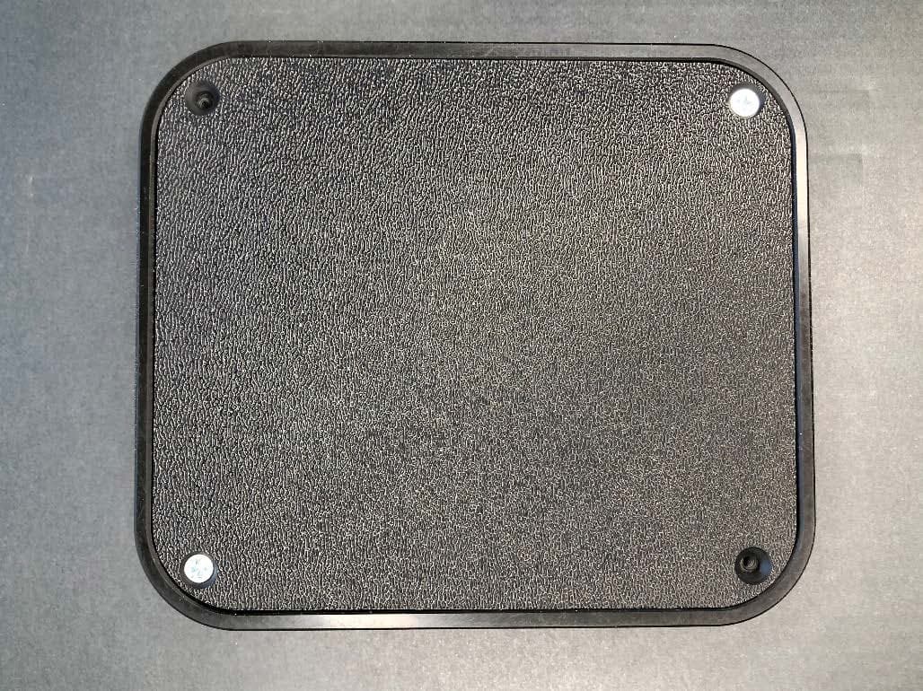
Click to zoom
Application Details
- Equipment Class
- 8CC - Part 18 Consumer Device
- Date of Grant
- Jul 11, 2021
- Application Purpose
- Original Equipment
- Date of Application
- Jun 10, 2021
- Equipment Note
- Wireless Charging Station
- Frequency Range
- 917.50000000 - 917.50000000
- Company
- 28 Gorilla
- Country
- United States
Documents & Files
Document Text
Text extracted from the exhibit documents filed with the FCC. Open a document above to read the original.
Users Manual
User Manual and User Information. User Manual and User Information Model: 28-0010366 28 Gorilla 12 S. San Marcos Place Chandler, AZ 85225 U.S.A. https://28gorilla.com Tel: 248-890-2098 Copyright © 2021 28 Gorilla Engineering. 28 Gorilla Engineering, the 28 Gorilla Engineering Logo, and other designated brands included herein are trademarks of 28 Gorilla Engineering in the United States and other countries. All other trademarks are the property of their respective owners. THE SPECIFICATIONS AND INFORMATION REGARDING THE PRODUCTS IN THIS MANUAL ARE SUBJECT TO CHANGE WITHOUT NOTICE. ALL STATEMENTS, INFORMATION, AND RECOMMENDATIONS IN THIS MANUAL ARE BELIEVED TO BE ACCURATE BUT ARE PRESENTED WITHOUT WARRANTY OF ANY KIND, EXPRESS OR IMPLIED. USERS MUST TAKE FULL RESPONSIBILITY FOR THEIR APPLICATION OF ANY PRODUCTS. THE SOFTWARE LICENSE AND LIMITED WARRANTY FOR THE ACCOMPANYING PRODUCT ARE SET FORTH IN THE INFORMATION PACKET THAT SHIPPED WITH THE PRODUCT AND ARE INCORPORATED HEREIN BY THIS REFERENCE. IF YOU ARE UNABLE TO LOCATE THE SOFTWARE LICENSE OR LIMITED WARRANTY, CONTACT YOUR 28 GORILLA REPRESENTATIVE FOR A COPY. 1. Intended Use 1. The purpose of this Charger is to charge receiver equipment outfitted with proprietary energy receiving circuits. The Charger can only be used in conjunction with devices that contain the receiving circuits for charging the native batteries of the equipment. 2. If a device that does not contain the proprietary receiver circuits, is placed on the charger. No charging will ensue and the Charger will not operate. 3. Equipment outfitted with inductive receiver circuits will not charge and the Charger will not operate. 4. The Charger will only operate once a receiver unit (Rx Unit) is placed on the charging area directly on top of the charger. 5. Indoor operation only --not to be used in a wet area, metal surface, or outdoors. User Manual and User Information. 6. This transmitter is designed to specifically used for AE Wireless Temperature Sensor, model: 28- 0010038. 2. User Operation The charger does not contain a power switch. Simply connect the USB-C cable end to the Charger and the USB-Type A cable end to the wall adapter power supply. When not charging, the charger is in standby mode. In order to charge a receiver, place the receiver equipment in the keyed slot on top of the charger in the appropriate orientation. The receiver equipment keyed slot should be face down towards the outer edge of the charger case. When the receiver equipment is placed correctly the top surface of the receiver equipment should be parallel with the surface of the charger. Once the receiver equipment is placed in the charger, the charger should commence charging within a few seconds. Consult the equipment’s user manual for the time duration and procedures for charging. 3. Radio Characteristics: The WPT transmitter nominal frequency is: 917.5MHz The WPT transmitter conducted average output power is: 29 dBm total The BLE transmitter operating frequency: 2402 – 2480MHz The BLE transmitter output power: -2.4dBm 4. USB-C Port Insert the designated USB-C end of the cable into the USB-C port of the charger. Also, place the type A USB end of the cable to the type A USB port of the electrical AC wall power supply. This will supply power to the charger used to charge the receiver equipment. 5. Packaging contents WPT Charging Station AC Wall Power Supply USB-C to USB Type A Charger cable User Manual and User Information User Manual and User Information. 6. FCC Regulatory Information FCC ID: 2AX2O-280010320 Model: 28-0010366 This device complies with Part 18 of the FCC Rules. This device complies with Part 15 of the FCC Rules. Operation is subject to the following two conditions: (1) This device may not cause harmful interference, and (2) This device must accept any interference received, including interference that may cause undesired operation. Note: This equipment has been tested and found to comply with the limits for a Class B digital device, pursuant to part 15 of the FCC Rules. These limits are designed to provide reasonable protection against harmful interference in a residential installation. This equipment generates, uses and can radiate radio frequency energy and, if not installed and used in accordance with the instructions, may cause harmful interference to radio communications. However, there is no guarantee that interference will not occur in a particular installation. If this equipment does cause harmful interference to radio or television reception, which can be determined by turning the equipment off and on, the user is encouraged to try to correct the interference by one or more of the following measures: • Reorient or relocate the equipment being interfered with. • Increase the separation between the charger and the equipment subject to interference. • Connect the equipment into an outlet on a circuit different from that to which the charger is connected. • Consult the dealer or an experienced radio/TV/electronics technician for help. CAUTION: Changes or modifications to this unit not expressly approved by the party responsible for compliance could void the user’s authority to operate the equipment. 7. RF Exposure Notice The charger employs receiver equipment proximity sensing. There are no user adjustments and charging commences only when the internal microcontroller detects valid receiver equipment and permits commencement of power transfer. After placing your receiver on the charger, maintain a 2.5cm separation distance to meet applicable requirements. User Manual and User Information. 8. Supplier’s Declaration of Conformity Model: 28-0010366 FCC ID: 2AX2O-280010320 This device complies with part 15 of the FCC Rules. Operation is subject to the following two conditions: (1) This device may not cause harmful interference, and (2) this device must accept any interference received, including interference that may cause undesired operation. Responsible Party in the USA: 28 Gor…
Text truncated - open the document above for the full version.
Attestation Statements
KDB 680106 explains when a PAG is required for WPT devices. The 6 conditions detailed in section 5 of that publication are addressed below. Power transfer frequency is less than 1 MHz. This device operates at 917.5 MHz Output power from each primary coil is less than or equal to 15 watts. The total transmitted power is 29dBm which is less than 1W The system may consist of more than one source primary coils, charging one or more clients. If more than one primary coil is present, the coil pairs may be powered on at the same time. This device has a single antenna with elements allowing up to four devices to be charged simultaneously Client device is placed directly in contact with the transmitter. The client device is placed on the charger. Mobile exposure conditions only (portable exposure conditions are not covered by this exclusion). The charger is designed for mobile use – it requires external power (via AC-DC adapter and USB-C interface). It does not include a battery and is not designed for portable use. The aggregate H-field strengths anywhere at or beyond 15 cm surrounding the device, and 20 cm away from the surface from all coils that by design can simultaneously transmit, and while those coils are simultaneously energized, are demonstrated to be less than 50% of the MPE limit. As this device operates at 917.5MHz RF exposure is addressed using SAR measurement and not by measurement of E- and H- fields. Due to the low SAR values measurements are made at distances much less than the 15cm / 20cm required by the KDB. Actual distances were 0mm from the front and sides, 25mm from the top surface and 25mm from the rear edge. All measured values are significantly lower than 50% of the limit at the reduced distance. The testing follows previous guidance for similar devices.
External Photos
Model: 28-0010366 External Photos Top View Bottom View Model: 28-0010366 External Photos Front View Rear View Model: 28-0010366 External Photos Left Side View Right Side View Model: 28-0010366 External Photos Power Supply View
ID Label/Location Info
Page 1 of 1 Label FCC ID: 2AX2O–280010320 Label Location: Bottom of the device 28 Gorilla, LLC 12 S San Marco Pl Chandler, AZ 85255 www.28gorilla.com
Internal Photos
Model: 28-0010366 Internal Photos Open Case View PCB Bottom View Model: 28-0010366 Internal Photos Antenna Top View Antenna Bottom View
RF Exposure Info
Plot No. 1 Test Laboratory: UL Verification Services Inc. SAR Lab F Date/Time: 5/11/2021 4:03:23 PM 20210511_ELI_SystemPerformanceCheck-D900V2 SN 1d143 Frequency: 900 MHz; Duty Cycle: 1:1; Room Ambient Temperature: 24.0°C; Liquid Temperature: 23.0°C Medium parameters used: f = 900 MHz; σ = 0.974 S/m; ε r = 39.671; ρ = 1000 kg/m 3 DASY5 Configuration: - Area Scan Setting: Find Secondary Maximum Within: 2.0 dB and with a peak SAR value greater than 0.0012W/kg - Electronics: DAE4 Sn1433; Calibrated: 2/24/2021 - Probe: EX3DV4 - SN7500; ConvF(9.5, 9.5, 9.5) @ 900 MHz; Calibrated: 3/18/2021 - Sensor-Surface: 2.5mm (Mechanical Surface Detection) - Phantom: ELI V5.0 Slot 6/7; Type: QD OVA 002 Ax; Serial: 1163 Head/Pin=100 mW/Area Scan (7x7x1): Measurement grid: dx=15mm, dy=15mm Maximum value of SAR (measured) = 1.33 W/kg Head/Pin=100 mW/Zoom Scan (7x7x7)/Cube 0: Measurement grid: dx=5mm, dy=5mm, dz=5mm Reference Value = 37.49 V/m; Power Drift = 0.05 dB Peak SAR (extrapolated) = 1.69 W/kg SAR(1 g) = 1.1 W/kg; SAR(10 g) = 0.702 W/kg Smallest distance from peaks to all points 3 dB below = 18.6 mm Ratio of SAR at M2 to SAR at M1 = 65% Maximum value of SAR (measured) = 1.36 W/kg 0 dB = 1.36 W/kg = 1.34 dBW/kg Plot No. 2 Test Laboratory: UL Verification Services Inc. SAR Lab F Date/Time: 5/11/2021 4:21:17 PM 20210511_ELI_SystemPerformanceCheck-D900V2 SN 1d143 Frequency: 900 MHz; Duty Cycle: 1:1 Head/Pin=100 mW/Z Scan (1x1x21): Measurement grid: dx=20mm, dy=20mm, dz=5mm Maximum value of SAR (measured) = 1.33 W/kg
RF Exposure Info
Plot No. 1 Test Laboratory: UL Verification Services Inc. SAR Lab F Date/Time: 5/12/2021 10:23:56 AM 917.5 MHz Frequency: 917.5 MHz; Duty Cycle: 1:1; Room Ambient Temperature: 24.0°C; Liquid Temperature: 23.0°C Medium parameters used (interpolated): f = 917.5 MHz; σ = 0.99 S/m; ε r = 39.454; ρ = 1000 kg/m 3 DASY5 Configuration: - Area Scan Setting: Find Secondary Maximum Within: 2.0 dB and with a peak SAR value greater than 0.0012W/kg - Electronics: DAE4 Sn1433; Calibrated: 2/24/2021 - Probe: EX3DV4 - SN7500; ConvF(9.5, 9.5, 9.5) @ 917.5 MHz; Calibrated: 3/18/2021 - Sensor-Surface: 2mm (Mechanical Surface Detection) - Phantom: ELI V5.0 Slot 6/7; Type: QD OVA 002 Ax; Serial: 1163 Front/917.5 MHz CW/ 25mm/ 1 Tag/Area Scan (12x13x1): Measurement grid: dx=15mm, dy=15mm Info: Interpolated medium parameters used for SAR evaluation. Maximum value of SAR (measured) = 0.391 W/kg Front/917.5 MHz CW/ 25mm/ 1 Tag/Zoom Scan (5x5x7)/Cube 0: Measurement grid: dx=8mm, dy=8mm, dz=5mm Reference Value = 18.99 V/m; Power Drift = 0.10 dB Peak SAR (extrapolated) = 0.482 W/kg SAR(1 g) = 0.318 W/kg; SAR(10 g) = 0.206 W/kg Smallest distance from peaks to all points 3 dB below = 20.4 mm Ratio of SAR at M2 to SAR at M1 = 65.8% Info: Interpolated medium parameters used for SAR evaluation. Maximum value of SAR (measured) = 0.407 W/kg 0 dB = 0.407 W/kg = -3.90 dBW/kg
RF Exposure Info
Head Tissue Simulating Liquids Head Tissue Parameters according to IEEE Std 1528-2013 / IEC 62209 / FCC KDB 865664 D01 Narrow- Band Solutions (±5% tolerance) Product HSL300V2 HSL450V2 HSL750V2 HSL900V2 HSL1450V2 HSL1750V2 HSL1800V2 HSL1900V2 HSL1950V2 HSL2450V2 Test Frequency (MHz) 300 450 750 835, 900 1450, 1500, 1640 1750 1800, 1900 1900 1950, 2000 2450, 2600 Main Ingredients Water, Sugar Water, Sugar Water, Sugar Water, Sugar Water, DGBE Water, DGBE Water, DGBE Water, DGBE Water, DGBE Water, DGBE Broad- Band Solutions (±5% tolerance) Product HBBL30-250V3 HBBL1350-1850V3 HBBL1550-1950V3 HBBL1900-3800V3 HBBL3500-5800V5 Test Frequency (MHz) 30-250 1400-1800 1750-1900 1950-3000 3500-5800 Main Ingredients Water, Tween Water, Tween Water, Tween Water, Tween Water, Oil Body Tissue Simulating Liquids Body Tissue (Muscle) Parameters according to FCC KDB 865664 D01 Narrow- Band Solutions (±5% tolerance) Product MSL300V2 MSL450V2 MSL750V2 MSL900V2 MSL1450V2 MSL1750V2 MSL1800V2 MSL1900V2 MSL1950V2 MSL2450V2 Test Frequency (MHz) 300 400, 450 750 835, 900 1450, 1500, 1640 1750 1800, 1900 1900 1950, 2100 2450, 2600 Main Ingredients Water, Sugar Water, Sugar Water, Sugar Water, Sugar Water, DGBE Water, DGBE Water, DGBE Water, DGBE Water, DGBE Water, DGBE Broad- Band Solutions (±5% tolerance) Product MBBL130-250V3 MBBL1350-1850V3 MBBL1550-1950V3 MBBL1900-3800V3 MBBL3500-5800V5 Test Frequency (MHz) 130-250 1350-1800 1550-1850 1950-3800 3500-5800 Main Ingredients Water, Tween Water, Tween Water, Tween Water, Tween Water, Oil
RF Exposure Info
CERTIFICATE OF CALIBRATION ISSUED BY UL INTERNATIONAL (UK) LTD DATE OF ISSUE: 29/Oct/2020 CERTIFICATE NUMBER : 13252590JD01A UL INTERNATIONAL (UK) LTD UNIT 1-3 HORIZON KINGSLAND PARK, WADE ROAD BASINGSTOKE, HAMPSHIRE RG24 8AH, UK TEL: +44 (0) 1256 312000 FAX: +44 (0) 1256 312001 Email: [email protected] Page 1 of 10 APPROVED SIGNATORY .................................... Harmohan Sahota Customer : UL VS Inc 47173 Benicia Street Fremont, CA 94538, USA Equipment Details: Description: Dipole Validation Kit Date of Receipt: 15/Oct/2020 Manufacturer: Speag Type/Model Number: D900V2 Serial Number: 1d143 Calibration Date: 21/Oct/2020 Calibrated By: Kaan Corbacioglu Laboratory Technician Signature: .................................... All Calibration have been conducted in the closed laboratory facility: Lab Temperature (22±3) 0 C and humidity < 70% This certificate is issued in accordance with the laboratory accreditation requirements of the United Kingdom Accreditation Service. It provides traceability of measurement to the SI system of units and/or to units of measurement realised at the National Physical Laboratory or other recognised national metrology institutes. This certificate may not be reproduced other than in full, except with the prior written approval of the issuing laboratory. Use of the UKAS mark demonstrates that compliance with the requirements of BS/EN/ISO/IEC 17025:2017 has been independently assessed. CERTIFICATE OF CALIBRATION ISSUED BY UL INTERNATIONAL (UK) LTD UKAS Accredited Calibration Laboratory No. 5772 CERTIFICATE NUMBER : 13252590JD01A Page 2 of 10 The calibration methods and procedures used were as detailed in: 1. IEC 62209-1:2016: Procedure to determine the specific absorption rate (SAR) for hand-held devices used in close proximity to the ear (frequency range of 300 MHz to 3 GHz) 2. IEC 62209-2:2010: Procedure to determine the specific absorption rate (SAR) for wireless communication devices used in close proximity to the human body (frequency range of 30 MHz to 6 GHz) 3. IEEE 1528: 2013: IEEE Recommended Practice for Determining the Peak Spatial-Average Specific Absorption Rate (SAR) in the Human Head from Wireless Communication Devices: Measurement Techniques 4. FCC KDB Publication Number: “KDB865664 D01 SAR Measurement 100 MHz to 6 GHz” 5. DASY5/6 System Handbook 6. Dipole Calibration Procedure V1.2: Calibration performed as per internal procedure The measuring equipment used to perform the calibration, documented in this certificate has been calibrated in accordance with the manufacturers’ recommendations, and is traceable to recognized national standards. UL No. Instrument Manufacturer Type No. Serial No. Date Last Calibrated Cal. Interval (Months) PRE0135115 Data Acquisition Electronics SPEAG DAE4 1438 14 Apr 2020 12 PRE0178314 Probe SPEAG EX3DV4 7496 24 Mar 2020 12 PRE0134199 Dipole SPEAG D900V2 035 11 Feb 2020 12 PRE0151451 Power Monitoring Kit Art-Fi ART 100850-01 0001 Cal as part of System - PRE0151441 Power Sensor Rhode & Schwarz NRP8S 102481 27 Mar 2020 12 PRE0151154 Vector Network Analyser Rhode & Schwarz ZNB 8 100151 15 Jun 2020 12 PRE0158684 Calibration Kit Rhode & Schwarz ZV-Z135 102144 27 May 2020 12 PRE0178154 Signal Generator Rhode & Schwarz SMB100A 175325 10 Jun 2020 12 CERTIFICATE OF CALIBRATION ISSUED BY UL INTERNATIONAL (UK) LTD UKAS Accredited Calibration Laboratory No. 5772 CERTIFICATE NUMBER : 13252590JD01A Page 3 of 10 SAR System Specification Robot System Positioner: Stäubli Unimation Corp. Robot Model: TX60L Robot Serial Number: F17/5ENYG1/A/01 DASY Version: cDASY6.14.0.959 Phantom: Flat section of SAM Twin Phantom Distance Dipole Centre: 15 mm (with spacer) Frequency: 900 MHz Dielectric Property Measurements – Head Simulating Liquid (HSL) Simulant Liquid Frequency (MHz) Room Temp Liquid Temp Parameters Target Value Measured Value Uncertainty (%) Start End Start End Head 900 20.1 °C 20.4 °C 20.0 °C 20.1 °C εr 41.50 41.72 ± 5% σ 0.97 0.93 ± 5% SAR Results – Head Simulating Liquid (HSL) Simulant Liquid SAR Measured 250 mW input Power Normalised to 1.00 W Uncertainty (%) Head SAR averaged over 1g 2.66 W/Kg 10.59 W/Kg ± 17.57% SAR averaged over 10g 1.74 W/Kg 6.93 W/Kg ± 17.32% Antenna Parameters – Head Simulating Liquid (HSL) Simulant Liquid Parameter Measured Level Uncertainty (%) Head Impedance 50.05 Ω - 0.19j Ω ± 0.28 Ω ± 0.044 jΩ Return Loss 53.99 ± 2.03 dB CERTIFICATE OF CALIBRATION ISSUED BY UL INTERNATIONAL (UK) LTD UKAS Accredited Calibration Laboratory No. 5772 CERTIFICATE NUMBER : 13252590JD01A Page 4 of 10 Dielectric Property Measurements – Body Simulating Liquid (MSL) Simulant Liquid Frequency (MHz) Room Temp Liquid Temp Parameters Target Value Measured Value Uncertainty (%) Start End Start End Body 900 19.4 °C 19.5 °C 19.9 °C 20.1 °C εr 55.00 55.49 ± 5% σ 1.05 1.00 ± 5% SAR Results – Body Simulating Liquid (MSL) Simulant Liquid SAR Measured 250 mW input Power Normalised to 1.00 W Uncertainty (%) Body SAR averaged over 1g 2.68 W/Kg 10.67 W/Kg ± 18.06% SAR averaged over 10g 1.77 W/Kg 7.05 W/Kg ± 17.44% Antenna Parameters – Body Simulating Liquid (MSL) Simulant Liquid Parameter Measured Level Uncertainty (%) Body Impedance 55.14 Ω + 1.57j Ω ± 0.28 Ω ± 0.044 jΩ Return Loss 25.83 ± 2.03 dB CERTIFICATE OF CALIBRATION ISSUED BY UL INTERNATIONAL (UK) LTD UKAS Accredited Calibration Laboratory No. 5772 CERTIFICATE NUMBER : 13252590JD01A Page 5 of 10 DASY Validation Scan for Head Stimulating Liquid (HSL) DUT: D900V2; Type: Dipole; Serial: SN1d143; Communication System: CW UID: 0; Frequency: 900.0 MHz; Duty Cycle: 1; Medium: HSL; Site65_21Oct2020_085903_Head - 900 2300 5%; Medium parameters used: f = 900.0 MHz; σ = 0.93 S/m; ε r = 41.7; ρ = 1000 kg/m3; Δε r = 0.53 %; Δσ = -3.71 %; No correction Phantom section: Flat; DASY 6 Configuration: - Laboratory Name: Site65; - Probe: EX3DV4 - SN7496; ConvF(9.65, 9.65, 9.65); Calibrated: 24 Mar 2020 - Sensor-Surface: 1.4 mm; VMS + 6p - Electronics: DAE4 - SN1438; Calibrated: 14 Apr 2020 - …
Text truncated - open the document above for the full version.
RF Exposure Info
NVLAP LAB CODE 200065-0 SAR EVALUATION REPORT FCC 47 CFR § 2.1093 IEEE Std 1528-2013 For Wireless Charging Station FCC ID: 2AX2O-280010320 Model Name: 28-0010366 Report Number: 13486961-S1V3 Issue Date: 6/28/2021 Prepared for 28 Gorilla, LLC. 12 S. San Marco Place Chandler, AZ 85255 Prepared by UL VERIFICATION SERVICES INC. 47173 BENICIA STREET FREMONT, CA 94538, U.S.A. TEL: (510) 319-4000 FAX: (510) 661-0888 Report No.: 13587871-S1V3 Issue Date: 6/28/2021 Page 2 of 18 UL Verification Services Inc. Doc. No.: 1.0 This report shall not be reproduced without the written approval of UL Verification Services Inc. Revision History Rev. Date Revisions Revised By V1 6/3/2021 Initial Issue -- V2 6/8/2021 Front page and Section 1 – Corrected FCC ID. Section 7 – Clarified edge 3 test distance. Section 11 – Corrected Bluetooth power. Appendix A – Corrected Photograph 7 distance to 25 mm. Dave Weaver V3 6/28/2021 Section 13 – Corrected SAR value in summation Dave Weaver Report No.: 13587871-S1V3 Issue Date: 6/28/2021 Page 3 of 18 UL Verification Services Inc. Doc. No.: 1.0 This report shall not be reproduced without the written approval of UL Verification Services Inc. Table of Contents 1. Attestation of Test Results ......................................................................................................... 4 2. Test Specification, Methods and Procedures ............................................................................ 5 3. Facilities and Accreditation ........................................................................................................ 6 4. SAR Measurement System & Test Equipment .......................................................................... 7 4.1. SAR Measurement System ........................................................................................................ 7 4.2. SAR Scan Procedures ............................................................................................................... 8 4.3. Test Equipment ........................................................................................................................ 10 5. Measurement Uncertainty ......................................................................................................... 10 6. Device Under Test (DUT) Information ...................................................................................... 11 6.1. DUT Description ...................................................................................................................... 11 6.2. Wireless Technologies ............................................................................................................. 11 7. RF Exposure Conditions (Test Configurations) ...................................................................... 11 8. Dielectric Property Measurements & System Check .............................................................. 12 8.1. Dielectric Property Measurements ........................................................................................... 12 8.2. System Check.......................................................................................................................... 13 9. Conducted Output Power Measurements ................................................................................ 14 10. Measured and Reported (Scaled) SAR Results ....................................................................... 14 10.1. CW 917.5 MHz ..................................................................................................................... 14 11. Standalone SAR Test Exclusion Considerations & Estimated SAR ...................................... 15 12. SAR Measurement Variability ................................................................................................... 16 13. Simultaneous Transmission Conditions ................................................................................. 17 Appendixes .......................................................................................................................................... 18 Appendix A: SAR Setup Photos ......................................................................................................... 18 Appendix B: SAR System Check Plots ............................................................................................... 18 Appendix C: SAR Highest Test Plots .................................................................................................. 18 Appendix D: SAR Tissue Ingredients .................................................................................................. 18 Appendix E: SAR Probe Certificates ................................................................................................... 18 Appendix F: SAR Dipole Certificates .................................................................................................. 18 Report No.: 13587871-S1V3 Issue Date: 6/28/2021 Page 4 of 18 UL Verification Services Inc. Doc. No.: 1.0 This report shall not be reproduced without the written approval of UL Verification Services Inc. 1. Attestation of Test Results Applicant Name 28 Gorilla, LLC. FCC ID 2AX2O-280010320 Model Name 28-0010366 Applicable Standards Published RF exposure KDB procedures IEEE Std 1528-2013 Exposure Category SAR Limits (W/Kg) Peak spatial-average (1g of tissue) Extremities (hands, wrists, ankles, etc.) (10g of tissue) General population / Uncontrolled exposure 1.6 4 RF Exposure Conditions Equipment Class - Highest Reported SAR (W/kg) CW DSS Body 0.318 N/A Simultaneous TX 0.326 Date Tested 5/11/2021-5/12/2021 Test Results Pass UL Verification Services Inc. tested the above equipment in accordance with the requirements set forth in the above standards. The test results show that the equipment tested is capable of demonstrating compliance with the requirements as documented in this report. The results documented in this report apply only to the tested sample, under th…
Text truncated - open the document above for the full version.
Test Report
FCC ID: 2AX2O–280010320 MEASUREMENT REPORT Approved by: Technical Manager Test Report S/N: Test Dates: EUT Type: Page 1 of 23 1C2101120008-04.2AX2O-R2 5/13/2021 - 5/17/2021 Wireless Charging Station © 2021 PCTEST V 10.3 11/16/2020 All rights reserved. Unless otherwise specified, no part of this report may be reproduced or utilized in any part, form or by any means, electronic or mechanical, including photocopying and microfilm, without permission in writing from PCTEST. If you have any questions about this international copyright or have an enquiry about obtaining additional rights to this report or assembly of contents thereof, please contact [email protected]. Applicant Name: 28 Gorilla, LLC. 12 S San Marco PI Chandler, AZ 85255 United States Date of Testing: 5/13/2021 - 5/17/2021 Test Site/Location: PCTEST. Morgan Hill, CA, USA Test Report Serial No.: 1C2101120008-04.2AX2O-R2 FCC ID: 2AX2O–280010320 APPLICANT: 28 Gorilla, LLC. Model: 28-0010366 EUT Type: Wireless Charging Station FCC Classification: Part 18 Consumer Device FCC Rule Part(s): FCC Part 18 Subpart C Test Procedure(s): FCC/OST MP-5 (1986) This equipment has been shown to be capable of compliance with the applicable technical standards as indicated in the measurement report and has been tested in accordance with the measurement procedures specified in FCC/OST MP-5 (1986). These measurements were performed with no deviation from the standards. Test results reported herein relate only to the item(s) tested. This revised Test Report (S/N: 1C2101120008-04.2AX2O-R2) supersedes and replaces the previously issued test report on the same subject device for the same type of testing as indicated. Please discard or destroy the previously issued test report(s) and dispose of it accordingly. I attest to the accuracy of data. All measurements reported herein were performed by me or were made under my supervision and are correct to the best of my knowledge and belief. I assume full responsibility for the completeness of these measurements and vouch for the qualifications of all persons taking them. PCTEST 18855 Adams Court, Morgan Hill, CA 95037 USA Tel. 410.290.6652 / Fax 410.290.6654 http://www.pctest.com MEASUREMENT REPORT FCC Part 18 FCC ID: 2AX2O–280010320 MEASUREMENT REPORT Approved by: Technical Manager Test Report S/N: Test Dates: EUT Type: Page 2 of 23 1C2101120008-04.2AX2O-R2 5/13/2021 - 5/17/2021 Wireless Charging Station © 2021 PCTEST V 10.3 11/16/2020 All rights reserved. Unless otherwise specified, no part of this report may be reproduced or utilized in any part, form or by any means, electronic or mechanical, including photocopying and microfilm, without permission in writing from PCTEST. If you have any questions about this international copyright or have an enquiry about obtaining additional rights to this report or assembly of contents thereof, please contact [email protected]. T A B L E O F C O N T E N T S 1.0 Introduction ...................................................................................................................................... 3 1.1 Scope..................................................................................................................................................... 3 1.2 PCTEST Test Location .......................................................................................................................... 3 1.3 Test Facility / Accreditations .................................................................................................................. 3 2.0 PRODUCT INFORMATION ............................................................................................................. 4 2.1 Equipment Description ........................................................................................................................... 4 2.2 Device Capabilities ................................................................................................................................ 4 2.3 Antenna Description............................................................................................................................... 4 2.4 Test Support Equipment ........................................................................................................................ 5 2.5 Test Configuration ................................................................................................................................. 5 2.6 Software and Firmware .......................................................................................................................... 5 2.7 EMI Suppression Device(s)/Modifications .............................................................................................. 5 3.0 DESCRIPTION OF TESTS .............................................................................................................. 6 3.1 Evaluation Procedure............................................................................................................................. 6 3.2 AC Line Conducted Emissions .............................................................................................................. 6 3.3 Radiated Emissions ..................................................................................…
Text truncated - open the document above for the full version.
Contact Information
Applicant
Andrew William Phillips(Princiap)
Technical Contact
UL VERIFICATION SERVICES INCANA AUMENTADO
[email protected]5103194007
47173 BENICIA ST · FREMONT · United States
Test Firm
Element Materials Technology San Jose, CARandy Ortanez
Technical Specifications
| # | Rule Parts | Frequency Range | Power Output |
|---|---|---|---|
| 1 | 18 | 917.5 MHz - 917.5 MHz | - |
Other Applications from 28 Gorilla

2AX2O-280010319
Jul 11, 2021AE WIRELESS TEMPERATURE SENSOR
Equipment Class
DTS - Digital Transmission System