2AX2R-PITATWS Bluetooth Earphone
final Inc.
Click to zoom
Application Details
- Equipment Class
- DSS - Part 15 Spread Spectrum Transmitter
- Date of Grant
- Dec 15, 2022
- Application Purpose
- Original Equipment
- Date of Application
- Dec 15, 2022
- Equipment Note
- TWS Bluetooth Earphone
- Frequency Range
- 2402.00000000 - 2480.00000000
- Company
- final Inc.
- Country
- Japan
Documents & Files
Document Text
Text extracted from the exhibit documents filed with the FCC. Open a document above to read the original.
Users Manual
Changes or modifications not expressly approved by the party responsible for compliance could void the user's authority to operate the equipment. This equipment has been tested and found to comply with the limits for a Class B digital device, pursuant to Part 15 of the FCC Rules. These limits are designed to provide reasonable protection against harmful interference in a residential installation. This equipment generates uses and can radiate radio frequency energy and, if not installed and used in accordance with the instructions, may cause harmful interference to radio communications. However, there is no guarantee that interference will not occur in a particular installation. If this equipment does cause harmful interference to radio or television reception, which can be determined by turning the equipment off and on, the user is encouraged to try to correct the interference by one or more of the following measures: -- Reorient or relocate the receiving antenna. -- Increase the separation between the equipment and receiver. -- Connect the equipment into an outlet on a circuit different from that to which the receiver is connected. -- Consult the dealer or an experienced radio/TV technician for help This device complies with part 15 of the FCC rules. Operation is subject to the following two conditions (1)this device may not cause harmful interference, and (2) this device must accept any interference received, including interference that may cause undesired operation. Our product TWS Bluetooth Earphone AG-PITA, ag ,doesn't have enough space to print the product name, model, trademark, MIC ID and MIC Logo on the product itself, thus we locate them on user manual and product packaging. Product : TWS Bluetooth Earphone Model number : AG-PITA FCC ID : 2AX2R-PITA Complies with IMDA Standards DA108470 210-195917 final TYPE E Ear Tips Package Contents Parts Name Earphone Units Charging Case USB Type-C Charging Cable LED Indicator Reset Button USB Port Power/ Charging Charging the charging case: Connect the accessory USB charging cable (C) connector to the USB port on the charging case and connect the USB (A) connector to an electrical appliance or adapter with the same shape of connector and the internal battery within the charging case will begin to charge with the LED Indicator lights up in White for 6 seconds. While charging, the LED Indicator of the charging case will blink/light up in different patterns depending on the battery power level of the charging case as shown in the table below. Charging the earphones: Insert the earphone units into the charging case and the earphone units will start charging with the LED Indicator on the earphones blinking slowly in Red. The LED Indicator will blink depending on the battery power level of the charging case as shown in the table below. Once the earphone units are completely charged, the LED Indicators on both earphone units and the charging case will go off. 23 Touch Control Panel LED Indicator Microphones LED Indicator of the Charging CaseCharging Case Battery Level 0 25 26 99 100 Blinks slowly in Red Blinks slowly in White Lights up in White LED Indicator of the Charging CaseCharging Case Battery Level 0 25 26 100 Blinks slowly in Red Blinks slowly in White LSSSMLL The power can also be turned ON by touching and holding the touch control panel for 4 seconds. * This action has to be performed independently on both Left and Right. Power ON When the charging case is adequately charged, returning the earphone units to the charging case and closing the charging case, the earphone units will be automatically powered OFF and charging will begin. The LED Indicator of the charging case will blink slowly in a different color depending on the battery power level of the charging case as shown in the table below P.3. The power can also be turned OFF by touching and holding the touch control panel of one of the earphones for 8 seconds until the LED Indicator of both earphones lights up Red and the power of both earphones will switch OFF. Power OFF ag_UZURA Device For the first time use : 1. Open the charging case, and the power of the earphones will turn ON with the LED Indicator on the earphones lights up in White for 2 seconds. Remove both of the earphones from the charging case and the earphones will switch into pairing mode with the LED Indicator of one of the earphones starts blinking Red and White alternately. *1 2. Switch the Bluetooth function on the smartphone or other devices ON and select [ ag_UZURA ] once it appears on the display. When [ ag_UZURA Connected ] *2 appears on the display of the device, the pairing has been completed. To reestablish pairing or to perform pairing with a second or subsequent devices: 1. Return both of the earphones to the charging case. Before pairing with a new device, please disconnect the earphones from the previously connected device or switch OFF the Bluetooth function of the previously connected device. 2. Open the charging case, and the power of the earphones will turn ON with the LED Indicator on the earphones lights up in White for 2 seconds. Remove both of the earphones from the charging case and the earphones will switch into pairing mode with the LED Indicator of one of the earphones starts blinking Red and White alternately. *1 3. Switch the Bluetooth function on the smartphone or other devices ON and select [ ag_UZURA ] once it appears on the display. When [ ag_UZURA Connected ] *2 appears on the display of the device, the pairing has been completed. *1: If the LED Indicators of earphone is blinking slowly in Red, it means that the earphones are being charged by the case. You can perform the pairing in this state if they are available on the display of device. *2: The content displayed differs depending on the user interface of the smartphones or other devices. To connect to your smartphone or other devices initially, it is necessary to perform pairing. For devices which have already completed pairing, a…
Text truncated - open the document above for the full version.
Cover Letter(s)
finalInc. 4-44-1,Nakasaiwai-cho,Saiwai-Ku,Kawasaki-shi,Kanagawa212-0012,Japan OfficeofEngineeringTechnology FederalCommunicationsCommission 7435OaklandMillsRoad Columbia,MD21046 USA Date:Nov.04,2022 Subject;RequestforConfidentiality FCCID:2AX2R-PITA ToWhomItMayConcern, PursuanttotheprovisionsoftheCommission’srulesTitle47Sections§0.457and§0.459,we arerequestingtheCommissiontowithholdthefollowingattachment(s)asconfidential documentsfrompublicdisclosureindefinitely. Thesedocumentscontaindetailedsystemandequipmentdescriptionsandareconsideredas proprietaryinformationinoperationoftheequipment.Thepublicdisclosureofthesedocuments mightbeharmfultoourcompanyandwouldgivecompetitorsanunfairadvantageinthemarket. SchematicDiagram BlockDiagram OperationalDescription PartsList Inadditionaltoabovementioneddocuments,inordertocomplywiththemarketingregulations inTitle47CFR§2.803andtheimportationrulesinTitle47CFR§2.1204,whileensuringthat businesssensitiveinformationremainsconfidentialuntiltheactualmarketingofnewly authorizeddevices,werequestShortTermConfidentialityofthefollowingattachment(s); ExternalPhotos TestSetupPhotos InternalPhotos UserManual For45days,pursuanttoPublicNoticeDA04-1705. OR For180dayspursuanttoKDB726920D01. Itisourunderstandingthatallmeasurementtestreports,FCCIDlabelformatand correspondenceduringthecertificationreviewprocesscannotbegrantedasconfidential documentsandthisinformationwillbeavailableforpublicreviewoncethegrantofequipment authorizationisissued. Sincerely, Signature: Name:NakamichiTakashi Title:Manager
External Photos
Report No.: AGC11059220901AP03 Page 1 of 4 EXTERNAL PHOTOS ALL VIEW OF EUT TOP VIEW OF EUT Report No.: AGC11059220901AP03 Page 2 of 4 BOTTOM VIEW OF EUT FRONT VIEW OF EUT Report No.: AGC11059220901AP03 Page 3 of 4 BACK VIEW OF EUT LEFT VIEW OF EUT Report No.: AGC11059220901AP03 Page 4 of 4 RIGHT VIEW OF EUT ****************************************End of Report****************************************
ID Label/Location Info
FCC ID Label Location The product does not have enough space to place the label, and FCC ID label is reflected in the user manual and package, as below:
Internal Photos
Report No.: AGC11059220901AP03 Page 1 of 6 INTERNAL PHOTOS OPEN VIEW OF EUT (Left) BATTERY VIEW OF EUT Report No.: AGC11059220901AP03 Page 2 of 6 INTERNAL VIEW OF EUT (FIGURE 1) INTERNAL VIEW OF EUT (FIGURE 2) Report No.: AGC11059220901AP03 Page 3 of 6 INTERNAL VIEW OF EUT (FIGURE 3) ANTENNA CLOSE-UP PHOTO-1 BT Antenna Report No.: AGC11059220901AP03 Page 4 of 6 OPEN VIEW OF EUT (Right) BATTERY VIEW OF EUT Report No.: AGC11059220901AP03 Page 5 of 6 INTERNAL VIEW OF EUT (FIGURE 1) INTERNAL VIEW OF EUT (FIGURE 2) Report No.: AGC11059220901AP03 Page 6 of 6 INTERNAL VIEW OF EUT (FIGURE 3) ANTENNA CLOSE-UP PHOTO-1 ****************************************End of Report**************************************** BT Antenna
RF Exposure Info
RF EXPOSURE EVALUATION 1. PRODUCT INFORMATION Product Description TWS Bluetooth Earphone Model Name AG-PITA FCC ID 2AX2R-PITA 2. EVALUATION METHOD According to 447498 D01 General RF Exposure Guidance v06 The 1-g and 10-g SAR test exclusion thresholds for 100 MHz to 6 GHz at test separation distances ≤ 50 mm are determined by: [(max. power of channel, including tune-up tolerance, mW)/(min. test separation distance, mm)] ·[√f(GHz)] ≤ 3.0 for 1-g SAR and ≤ 7.5 for 10-g extremity SAR. Where f(GHz) is the RF channel transmit frequency in GHz Power and distance are rounded to the nearest mW and mm before calculation 3. CALCULATION P t = -5.298dBm=0.30mW The value of the Maximum output power P t is referred to the test report of the CFR47 §15.247. The result for RF exposure evaluation SAR=(0.30mW /5mm) .[√2.480GHz)]=0.09<3.0 for 1-g SAR and ≤ 7.5 for 10-g extremity SAR. 4. CONCLUSION The SAR evaluation is not required.
Test Report
final Inc. 4-44-1, Nakasaiwai-cho, Saiwai-Ku, Kawasaki-shi, Kanagawa 212-0012, Japan Agent Authorization Company: final Inc. Address: 4-44-1, Nakasaiwai-cho, Saiwai-Ku, Kawasaki-shi, Kanagawa 212-0012, Japan Product Name: TWS Bluetooth Earphone Model Number(s): AG-PITA Product Description: TWS Bluetooth Earphone We authorize MiCOM Labs Inc., 575 Boulder Court, Pleasanton, California 94566, USA, to act on our behalf on all matters concerning the certification of above named equipment. We declare that MiCOM Labs Inc. is allowed to forward all information related to the approval and certification of equipment to the regulatory agencies as required and to discuss any issues concerning the approval application. Any and all acts carried out by MiCOM Labs on our behalf shall have the same effect as acts of our own. Signature: Date: Nov. 04, 2022 Name: Nakamichi Takashi Title: Manager Company: final Inc.
Test Report
Page 1 of 58 FCC Test Report Report No.: AGC11059220901FE03 FCC ID : 2AX2R-PITA APPLICATION PURPOSE : Original Equipment PRODUCT DESIGNATION : TWS Bluetooth Earphone BRAND NAME : ag MODEL NAME : AG-PITA APPLICANT : final Inc. DATE OF ISSUE : Oct. 21, 2022 STANDARD(S) : FCC Part 15.247 REPORT VERSION : V1.0 Attestation of Global Compliance (Shenzhen) Co., Ltd Report No.: AGC11059220901FE03 Page 2 of 58 REPORT REVISE RECORD Report Version Revise Time Issued Date Valid Version Notes V1.0 / Oct. 21, 2022 Valid Initial Release Report No.: AGC11059220901FE03 Page 3 of 58 TABLE OF CONTENTS 1. VERIFICATION OF CONFORMITY .................................................................................................................. 5 2. GENERAL INFORMATION .............................................................................................................................. 6 2.1. PRODUCT DESCRIPTION ........................................................................................................................ 6 2.2. TABLE OF CARRIER FREQUENCYS ....................................................................................................... 6 2.3. RECEIVER INPUT BANDWIDTH .............................................................................................................. 7 2.4. EXAMPLE OF A HOPPING SEQUENCY IN DATA MODE ......................................................................... 7 2.5. EQUALLY AVERAGE USE OF FREQUENCIES AND BEHAVIOUR ......................................................... 7 2.6. RELATED SUBMITTAL(S) / GRANT (S) .................................................................................................... 8 2.7. TEST METHODOLOGY ............................................................................................................................. 8 2.8. SPECIAL ACCESSORIES ......................................................................................................................... 8 2.9. EQUIPMENT MODIFICATIONS ................................................................................................................. 8 2.10. ANTENNA REQUIREMENT..................................................................................................................... 8 3. MEASUREMENT UNCERTAINTY ................................................................................................................... 9 4. DESCRIPTION OF TEST MODES ................................................................................................................. 10 5. SYSTEM TEST CONFIGURATION ................................................................................................................. 11 5.1. CONFIGURATION OF EUT SYSTEM ....................................................................................................... 11 5.2. EQUIPMENT USED IN TESTED SYSTEM ............................................................................................... 11 5.3. SUMMARY OF TEST RESULTS ............................................................................................................... 11 6. TEST FACILITY .............................................................................................................................................. 12 7. PEAK OUTPUT POWER ................................................................................................................................ 13 7.1. MEASUREMENT PROCEDURE ............................................................................................................. 13 7.2. TEST SET-UP (BLOCK DIAGRAM OF CONFIGURATION) .................................................................... 13 7.3. LIMITS AND MEASUREMENT RESULT .................................................................................................. 14 8. 20DB BANDWIDTH ........................................................................................................................................ 18 8.1. MEASUREMENT PROCEDURE ............................................................................................................. 18 8.2. TEST SET-UP (BLOCK DIAGRAM OF CONFIGURATION) .................................................................... 18 8.3. LIMITS AND MEASUREMENT RESULTS ............................................................................................... 19 9. CONDUCTED SPURIOUS EMISSION........................................................................................................... 23 9.1. MEASUREMENT PROCEDURE ............................................................................................................. 23 9.2. TEST SET-UP (BLOCK DIAGRAM OF CONFIGURATION) .................................................................... 23 9.3. MEASUREMENT EQUIPMENT USED .................................................................................................... 23 9.4. LIMITS AND MEASUREMENT RESULT .................................................................................................. 23 10. RADIATED EMISSION ................................................................................................................................. 37 Report No.: AGC11059220901FE03 Page 4 of 58 10.1. MEASUREMENT PROCEDURE ........................................................................................................... 37 10.2. TEST SETUP ......................................................................................................................................... 39 10.3. LIMITS AND MEASUREMENT RESULT ............................................................................................... 40 10.4. TEST RESULT........................................................................................................................................ 40 11. NUMBER OF HOPPING FREQUENCY ..........................................................................................…
Text truncated - open the document above for the full version.
Test Report
PRODUCT SPECIFICATION PRODUCT NAME: PITA PRODUCT NUMBER: PITA CUSTOMER NUMBER: Write: zeng Proofread: zeng Approve: zhang Date: 2022.08.29 SHENZHEN HXD COMMUNICATION TECH CO.,LTD. TEL:0755-61123122 FAX:0755-61123480 document number (Doc. No.):SPEC-001 versions (Rev.):1.0 Antenna Specification Trade namePITA Type bluetooth headset 电 气 性 能 1. bandwidth 2.402GHz ~2.480GHz 2. impedance 50 Ω 3. VSWR When assembled with the specified prototype, it is placed naturally for determination。 2.402GHz ~2.480GHz 1.5 以下 4.GAIN 2.402GHz ~2.480GHz GAIN=3.19dBi(Typical) test method: (一) The antenna under test (DUT) is assembled on the specified prototype。 (二) Connect the test point on the test piece to the network analyzer with a 50Ω coaxial cable,The test cables are fitted with magnetic rings to reduce the effect of induced currents (三) The prototype was placed on a support with a height of 20cm to test the VSWR in OPEN or CLOSE (四) . Install the test circuit as shown below. (五). There are no special requirements for the test environment.(there is no large metal around, and it should be carried out in normal temperature and humidity 网络分析仪 样机 支撑架 同轴电缆 Sample Bracket net analyze coaxialcable 电 气 性 能 4. power 1W 5. temperature -25~+65 °C 6.temp -40~+85°C document number(Doc. No.):SPEC-001 versions(Rev.):1.0 Antenna Specification Trade name PITA Typebluetooth headset BLUE TOOTH ANTENNA Match thatE12PF/ E20R/ E3NC/ It matches left and right Type of antenna Type of antenna FPC antenna document number(Doc. No.):SPEC-001 versions(Rev.):1.0 A ntenna Specification Trade name PITA Typebluetooth headset RETURN LOSS document number(Doc. No.):SPEC-001 versions(Rev.):1.0 Antenna Specification Trade name PITA Typebluetooth headset Y-Z PLANE document number(Doc. No.):SPEC-001 versions(Rev.):1.0 Antenna Specification Trade name PITA Type bluetooth headset X-Y PLANE document number(Doc. No.):SPEC-001 versions(Rev.):1.0 Antenna Specification Trade name PITA Type bluetooth headset X-Z PLANE document number(Doc. No.):SPEC-001 versions(Rev.):1.0 Antenna Specification Trade name PITA Type bluetooth headset
Test Setup Photos
Report No.: AGC11059220901AP02 Page 1 of 2 TEST SETUP PHOTOS RADIATED EMISSION TEST SETUP BELOW 1GHz RADIATED EMISSION TEST SETUP ABOVE 1GHz Report No.: AGC11059220901AP02 Page 2 of 2 RF CONDUCTED TEST SETUP ****************************************End of Report*************************************
Contact Information
Applicant
Nakamichi Takashi(Manager)
Technical Contact
Test Firm
Attestation of Global Compliance (Shenzhen) Co., LDoris Li
[email protected]+86-755-25234088
Technical Specifications
| # | Rule Parts | Frequency Range | Power Output |
|---|---|---|---|
| 1 | 15C | 2.40 GHz - 2.48 GHz | 300.00 µW |
Other Applications from final Inc.

2AX2R-GEAR01
Jul 18, 2023TWS Bluetooth Earphone
Equipment Class
DSS - Part 15 Spread Spectrum Transmitter
2AX2R-UZURA
Dec 13, 2022TWS Bluetooth Earphone
Equipment Class
DSS - Part 15 Spread Spectrum Transmitter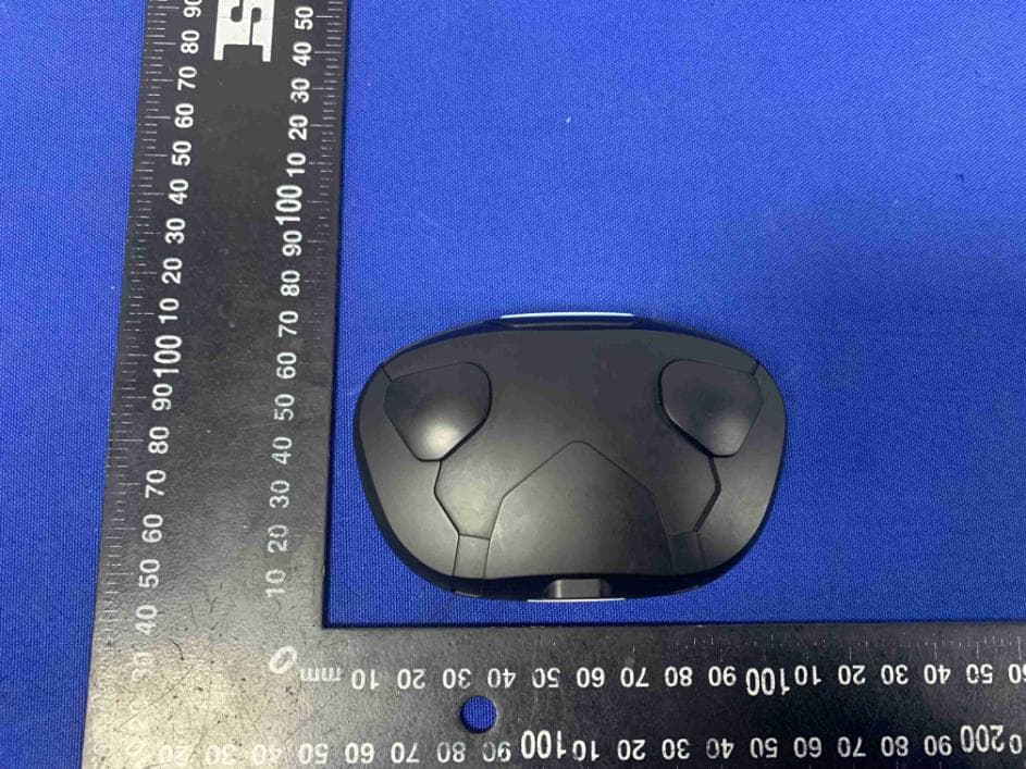
2AX2R-FI-EVATW
May 06, 2022True Wireless Earphone
Equipment Class
DSS - Part 15 Spread Spectrum Transmitter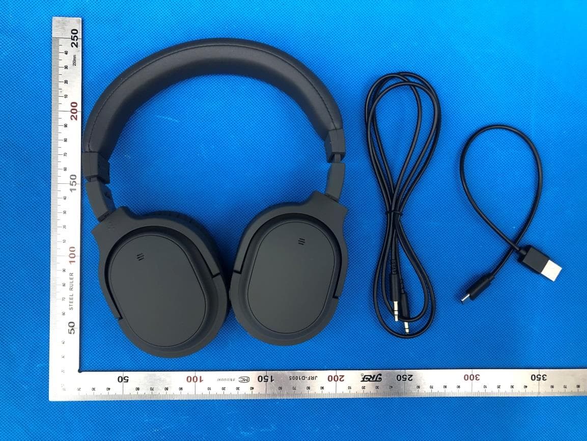
2AX2R-WHP01K
Jul 29, 2021Bluetooth Headphone
Equipment Class
DSS - Part 15 Spread Spectrum Transmitter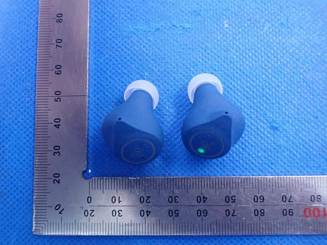
2AX2R-TWS08R
Apr 13, 2021TWS Bluetooth Earphone
Equipment Class
DSS - Part 15 Spread Spectrum Transmitter