2AXAA-HN022-01VMicrowave Motion Sensor
CWCE Lighting (Shenzhen) Co., Ltd.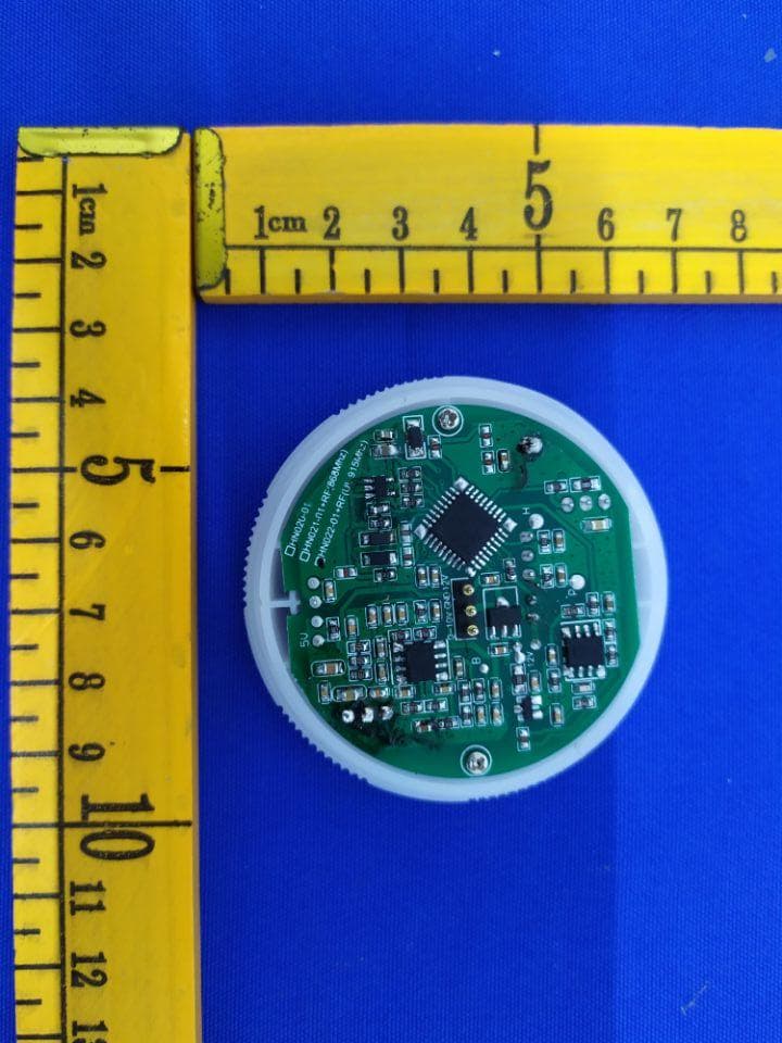
Click to zoom
Application Details
- Equipment Class
- DXX - Part 15 Low Power Communication Device Transmitter
- Date of Grant
- Sep 14, 2020
- Application Purpose
- Original Equipment
- Date of Application
- Sep 14, 2020
- Equipment Note
- Microwave Motion Sensor
- Frequency Range
- 915.00000000 - 915.00000000
- Country
- China
Documents & Files
Document Text
Text extracted from the exhibit documents filed with the FCC. Open a document above to read the original.
Users Manual
INSTRUCTION MANUAL FOR RF WIRELESS SENSOR DETACHED VERSION, MODEL NO.: HN020-01V / HN021-01V / HN022-01 Technical Specifications Microwave Motion Sensor 12VDC/50mA 5.8GHz CW radar 30° ~ 150° <1W Max. 16 x 12m 30s ~ 30min. 2 ~ 500Lux; disable 0s, 10s ~ 1h, +∞ 10% ~50% Indoors, ceiling & wall mounted -20 ~ +60 HN020-01V Microwave / constant illumination HN021-01V Microwave / constant illumination+ RF(868MHz) HN022-01V Microwave / constant illumination+ RF (UL 915MHz) PRODUCT TYPE: OPERATING VOLTAGE: HF SYSTEM: DETECTION ANGLE: POWER CONSUMPTION: DETECTION RANGE (DxH): HOLD TIME: DAYLIGHT SENSOR: STAND-BY PERIOD: STAND-BY DIMMING LEVEL: MOUNTING: WORKING TEMP.: MODEL: 3rd Floor, block C, complex building, 155#, Bai'gang road south, Bai'gang village, Xiao Jin Kou town, Huicheng district, Huizhou 516023 Tel:86-752-2772020 F:86-752-2777877 E: [email protected] W:www.hytronik.com CHINA FACTORY Room D, 10/f, Tower A, Billion Center, 1 wang Kwong Road, Kowloon Bay, Kowloon, Hongkong T: 00852-35197525 F: 00852-30116936 E: [email protected] HYTRONIK INDUSTRIAL LIMITED Microwave mount a b Silica gel soft φ 1 Typical Applications ULTRANIK HF motion detector A Daylight Harvest The motion detector can turn on the light based on movement. With this detector built in, light is automatically on when needed and dimmed to preset level before it is totally off. The light keeps off during daytime even when movement is detected. (Ambient lux level is above preset daylight threshold) With movement and insufficien tambient lux level, the light is triggered on 100% by the detector. The light turns off automatically after stand-by time. If there is no more movement, the light dims to stand-by dimming level after hold-time. The sensor highbay turns on at full or dims to maintain the lux level. The light output regulates according to level of natural light available ...... 1 2 43 SECTION 1 TYPICAL APPLICATIONS 2 Detection Pattern height (m) height (m) high sensitivity area low sensitivity areahigh sensitivity area low sensitivity area Ceiling mounting (m)Wall mounting (m) 3 10%OffOff 100%100%100% OffOffOff OffOffOff master slave 1 100%100%100% 100%100% 10% OffOff OffOffOff 2 While the 1st sensor detects motion on the 1st floor, it switches the light on at 100% and sends signal to all slave units. All slaves on the 1st floor turn on and the sensor highbay on the 2nd floor switches on at stand-by level. The person walks to the 2nd floor, the 2nd Sensor highbay switches the light on at 100%. All slaves on the 2nd floor turn the light on and the Sensor highbay on the 3rd floor switches on at stand-by level. B For staircase and corridor (master and slave) master slave 100%100% 10%10%10% 100% 100%100% 10%OffOff 3 10%10%10% OffOffOff 100%100% 100%100%100% 4 The person walks to the 3rd floor, the 3rd sensor highbay switches the light on 100%. All slaves on the 3rd floor turn the light on and the Sensor highbay on the 4th floor switches onat stand-by level. Meanwhile, the lights on the 1st floor are dimmed to stand-by level after hold-time. The person walks to the 4th floor, the 4th sensor highbay switches the light on at 100%. All slaves on the 4th floor turn the light on Meanwhile, all sensors on the 1st floor turn the light off after stand-by period, and all lights on the 2nd floor dim to stand-by level after hold-time. master slave master slave SECTION2 REMOTE CONTROL Note: the red LED indicator flash one time when RC receives signal successfully 1. Press button “st art” to program. 2. Select the buttons in “Detection range”, / “Daylight hreshold”, “Hold time”, “Stand-by time”, “Stand-by dimming level” to set all parameters. Scene prog. [ zone ] (One-key-commissioning) RESET[ button ] Press button , all settings go back to the default settings: Detection range: 100% Hold time: 1min Stand-by period: 5min Stand-by dimming level: 20% Daylight sensor: LUX disable Shift [ button ] Press button , the LED on the top left corner will flash to indicate mode selection. All values / settings in RED are valid for 20 seconds. Auto Mode [ button ] Press button to initiat e automatic mode. The sensor starts working and all settings remain as before the light was switched ON/OFF. Brightness +/- [ button ] Press button to adjust the light brightness between 10%~100% . 6 6 7 Power output [ button ] Press button , the light output shifts between 80% and 100%. Note: the function of “Sensor off” and “Twilight” are disabled. Permanent ON/OFF [ button ] Press button ,to select permanent ON or permanent OFF mode. * Press button / to resume automatic operation. The mode will change to AUTO Mode after power failure. 1 1 24 2 2 3 3 4 4 5 5 8 9 10 11 12 13 Semi-auto Mode [ button & ] 1. Press button Shift (the red LED is on for indication), 2. press button to initiat e semi-auto mode. The fixt ure is manually on by push-switch and automatically off in semi-auto mode. 3 3 4 4 1 3 7 9 6 8 10 11 13 14 12 2 4 5 HRC-11 & A 4 3. Press button “Memory” to save all the settings programmed in the remote control. 4. Press button “Apply” to set the settings to each sensor unit(s). For example, to pre-set detection range 100%, daylight threshold Disable, hold time 5min, stand-by time +∞, stand-by dimming level 30%, the steps should be as follows: Press button Start, button 100%, Disable, Shift, 5min, Shift, +∞, 30%, Memory. By pointing to the sensor unit(s) and pressing Apply, all settings are passed on the sensor(s). 7 Detection range [ zone ] Press buttons in zone to set detection range at 100% / 75%/ 50% / 10%. Daylight threshold [ zone ] Press buttons in zone to set the daylight sensor at 2Lux / 10Lux / 50Lux / 100Lux / 300Lux / 500Lux or Disable. Note: To set daylight sensor at 100Lux / 300 Lux / 500Lux, press button Shift at first. Ambient daylight threshold [ button ] 1. Press button Shift, the red LED is on for indication. 2. Press button ,the ambient lux level is sampled and set as the new daylight threshold. Press buttons in zone to set the hold time …
Text truncated - open the document above for the full version.
Cover Letter(s)
DATE :2020.08.22 Equipment Autorisation Division Federal Communications Commission 7435 Oakland Mills Road Columbia, MD 21046 FCC ID: _ 2AXAA-HN022-01V __ Product Name: _ Microwave Motion Sensor _____ Request for Confidentiality Pursuant to Sections 0.457 and 0.459 of the commission’s rules, we hereby request that the following documents be held confidential: (List here the documents for which you are seeking confidentiality – for example ...) Schematics Block diagram Operation description Part list These materials contain trade secrets and proprietary information and are not customarily released to the public. The public disclosure of this information might be harmful to the company and provide unjustified benefits to our competitors. <Signature> Name: Li Qiu Yong Title: Manager Applicant Company: CWCE Lighting (Shenzhen) Co., Ltd.
Cover Letter(s)
DATE :2020.08.22 Federal Communications Commission Authorization & Evaluation Division 7345 Oakland Mills Road Columbia, Maryland 21046 Authority to Act as Agent On our behalf, I appoint Dongguan New Testing Centre Co., Ltd;3F, No. 1 the 1st North Industry Road, Songshan Lake Science & Technology Park, Dongguan, Guangdong, China, 523808. to act as our agent in the preparation of this application for equipment certification. I certify that submitted documents properly describe the device or system for which equipment certification is sought. I also certify that each unit manufactured, imported or marketed, as defined in the Federal Communications Commission’s regulations will have affixed to it a label identical to that submitted for approval with this application. For instances where our authorized agent signs the application for certification on our behalf, I acknowledge that all responsibility for complying with the terms and conditions for certification, still resides with CWCE Lighting (Shenzhen) Co., Ltd.; A/area, 9F/Bldg,Cuijing Rd 28, Longtian Town,Pingshan New District,SHENZHEN Guangdong 518122 <Signature> Name: Li Qiu Yong Title: Manager Applicant Company: CWCE Lighting (Shenzhen) Co., Ltd.
External Photos
External photos Model No: HN022-01V
ID Label/Location Info
Label and label location Model No: HN022-01V FCC ID: 2AXAA-HN022-01V
Internal Photos
Internal Photos Model No: HN022-01V 5.8GHz Antenna 915MHz Antenna
Test Report
FCC TEST REPORT Report No. ....................................... : NTC-ER2007073 Applicant’s name ............................ : CWCE Lighting (Shenzhen) Co., Ltd. Address ............................................. : A/area, 9F/Bldg,Cuijing Rd 28, Longtian Town,Pingshan New District,SHENZHEN Guangdong 518122 Dongguan New Testing Centre Co., Ltd E-mail: [email protected] 3F, No. 1 the 1st North Industry Road, Songshan Lake Science & Technology Park, Dongguan, Guangdong, China, 523808 Page 1 of 24 Report No.: NTC-ER2007073 TABLE OF CONTENTS Test Report Declare ...................................................................................................................... 3 1. Summary of test results ........................................................................................................... 3 2. General test information .......................................................................................................... 3 2.1. Description of EUT ................................................................................................................... 3 2.2. Detail models ............................................................................................................................. 3 2.3. Block diagram EUT configuration for test ............................................................................. 3 2.4. Test environment conditions ................................................................................................... 4 2.5. Measurement uncertainty ........................................................................................................ 4 2.6. Support Equipment ..................................................................................................................... 4 3. Power Line Conducted Emission Test .................................................................................. 5 3.1. Test equipment ......................................................................................................................... 5 3.2. Block diagram of test setup ..................................................................................................... 5 3.3. Power Line Conducted Emission Limits (Class B) .............................................................. 5 3.4. Test Procedure .......................................................................................................................... 6 3.5. Test Result ................................................................................................................................. 6 4. Radiated emission test ............................................................................................................. 9 4.1. Test equipment ......................................................................................................................... 9 4.2. Block diagram of test setup ................................................................................................... 10 4.3. Limit .......................................................................................................................................... 12 4.4. Test Procedure ........................................................................................................................ 13 4.5. Test result ................................................................................................................................ 13 5. -20dB Bandwidth .................................................................................................................... 17 5.1. Test equipment ....................................................................................................................... 17 5.2. Block diagram of test setup ................................................................................................... 17 5.3. Limit .......................................................................................................................................... 17 5.4. Test Procedure ........................................................................................................................ 17 5.5. Test result ................................................................................................................................ 18 6. Antenna Requirements .......................................................................................................... 19 6.1. Limit .......................................................................................................................................... 19 6.2. Result........................................................................................................................................ 19 7. Test setup photograph ........................................................................................................... 20 6.1. Photos of power line conducted emission test .................................................................. 20 6.2. Photos of radiated emission test.......................................................................................... 20 8. Photos of the EUT .................................................................................................................. 22 Dongguan New Testing Centre Co., Ltd E-mail: [email protected] 3F, No. 1 the 1st North Industry Road, Songshan Lake Science & Technology Park, Dongguan, Guangdong, China, 523808 Page 2 of 24 Report No.: NTC-ER2007073 TEST REPORT DECLARE Test Standard Used: FCC Rules and Regulations Part 15 Subpart C: 2017, ANSI C63.10:2013. We Declare: The equipment described above is tested by Dongguan New Testing Centre Co., Ltd and in the configuration tested the equipment complied with the standards specified above. The test results are contained in this test report and Dongguan New Testing Centre Co., Ltd is assumed of full responsibility for the accuracy and completeness of these tests. After test and e…
Text truncated - open the document above for the full version.
Test Report
Dongguan New Testing Centre Co., Ltd E-mail: [email protected] 3F, No. 1 the 1st North Industry Road, Songshan Lake Science & Technology Park, Dongguan, Guangdong, China, 523808 FCC TEST REPORT Report No. ........... : NTC-ER2007072 Applicant’s name : CWCE Lighting (Shenzhen) Co., Ltd. Address ................ : A/area, 9F/Bldg,Cuijing Rd 28, Longtian Town,Pingshan New District,SHENZHEN Guangdong 518122 Dongguan New Testing Centre Co., Ltd E-mail: [email protected] 3F, No. 1 the 1st North Industry Road, Songshan Lake Science & Technology Park, Dongguan, Guangdong, China, 523808 Page 1 of 24 Report No.:NTC-ER2007072 TABLE OF CONTENTS Test Report Declare ...................................................................................................................... 3 1. Summary of test results ........................................................................................................... 3 2. General test information .......................................................................................................... 3 2.1. Description of EUT ................................................................................................................... 3 2.2. Detail models ............................................................................................................................. 4 2.3. Block diagram EUT configuration for test ............................................................................. 4 2.4. Test environment conditions ................................................................................................... 4 2.5. Measurement uncertainty ........................................................................................................ 5 2.6. Support Equipment ..................................................................................................................... 5 3. Power Line Conducted Emission Test .................................................................................. 6 3.1. Test equipment ......................................................................................................................... 6 3.2. Block diagram of test setup ..................................................................................................... 6 3.3. Power Line Conducted Emission Limits (Class B) .............................................................. 6 3.4. Test Procedure .......................................................................................................................... 7 3.5. Test Result ................................................................................................................................. 7 4. Radiated emission test ........................................................................................................... 10 4.1. Test equipment ....................................................................................................................... 10 4.2. Block diagram of test setup ................................................................................................... 11 4.3. Limit .......................................................................................................................................... 13 4.4. Test Procedure ........................................................................................................................ 14 4.5. Test result ................................................................................................................................ 14 5. -20dB Bandwidth .................................................................................................................... 18 5.1. Test equipment ....................................................................................................................... 18 5.2. Block diagram of test setup ................................................................................................... 18 5.3. Limit .......................................................................................................................................... 18 5.4. Test Procedure ........................................................................................................................ 18 5.5. Test result ................................................................................................................................ 19 6. Antenna Requirements .......................................................................................................... 20 6.1. Limit .......................................................................................................................................... 20 6.2. Result........................................................................................................................................ 20 7. Test setup photograph ........................................................................................................... 21 7.1. Photos of power line conducted emission test ................................................................... 21 7.2. Photos of radiated emission test .......................................................................................... 21 8. Photos of the EUT .................................................................................................................. 23 Dongguan New Testing Centre Co., Ltd E-mail: [email protected] 3F, No. 1 the 1st North Industry Road, Songshan Lake Science & Technology Park, Dongguan, Guangdong, China, 523808 Page 2 of 24 Report No.: NTC-ER2007072 TEST REPORT DECLARE Test Standard Used: FCC Rules and Regulations Part 15 Subpart C: 2017, ANSI C63.10:2013. We Declare: The equipment described above is tested by Dongguan New Testing Centre Co., Ltd and in the configuration tested the equipment complied with the standards specified above. The test results are contained in this test report and Dongguan New Testing Centre Co., Ltd is assumed…
Text truncated - open the document above for the full version.
Test Setup Photos
Setup photos Model No: HN022-01V Conducted emission test Radiated emission test 30MHz – 1GHz Above 1GHz
Contact Information
Applicant
Li Qiu Yong(Manager)
Test Firm
Dongguan NTC CO., Ltd.Jees Hong
[email protected]+86-769-22022444
Technical Specifications
| # | Rule Parts | Frequency Range | Power Output |
|---|---|---|---|
| 2 | 15C | 915 MHz - 915 MHz | - |
Other Applications from CWCE Lighting (Shenzhen) Co., Ltd.
2AXAA-HN030-01
Nov 06, 2020Li Qiu Yong
Equipment Class
DTS - Digital Transmission System
2AXAA-HN020-01V
Sep 14, 2020Microwave Motion Sensor
Equipment Class
DXX - Part 15 Low Power Communication Device Transmitter