2AXBN-CG7Wireless Smart Battery Camera
SHENZHEN CYTON Intelligence Technology CO.,LTD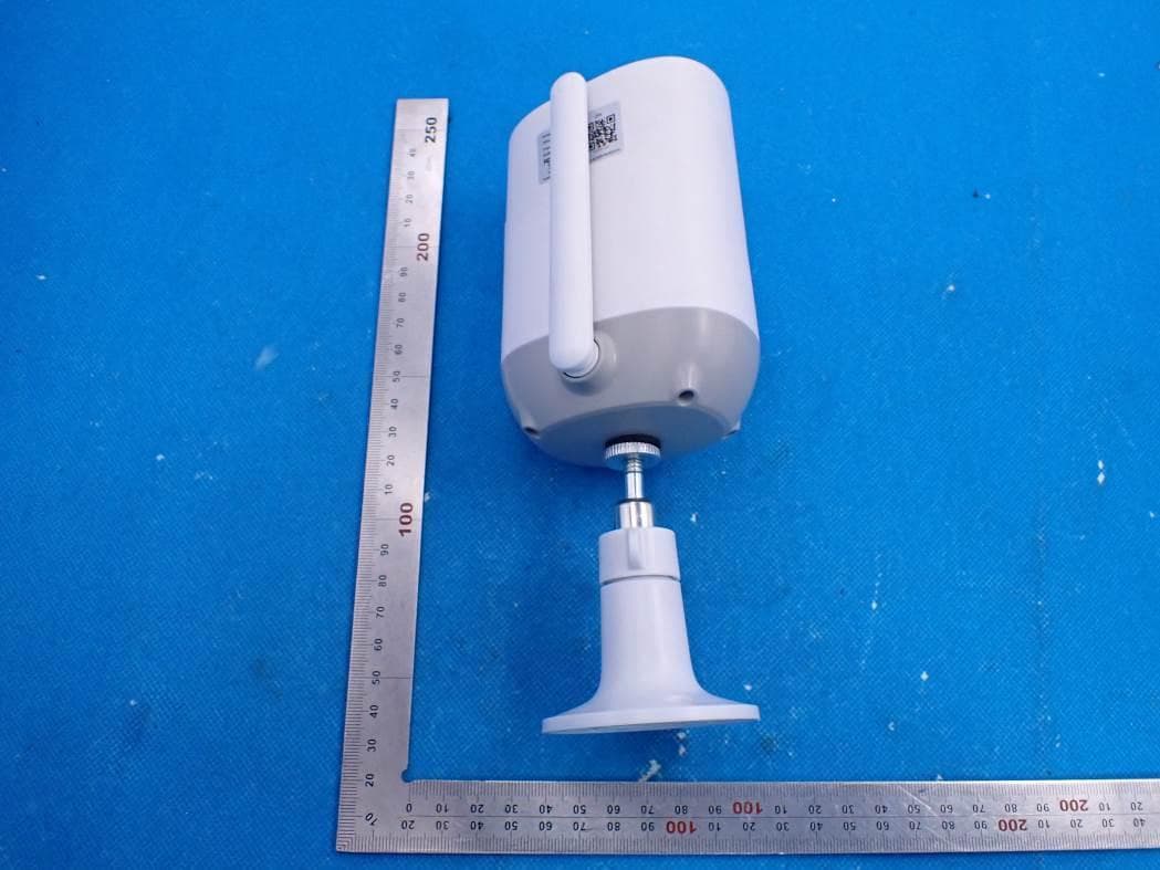
Click to zoom
Application Details
- Equipment Class
- DTS - Digital Transmission System
- Date of Grant
- Aug 25, 2021
- Application Purpose
- Original Equipment
- Date of Application
- Aug 25, 2021
- Equipment Note
- Wireless Smart Battery Camera
- Frequency Range
- 2412.00000000 - 2462.00000000
- Country
- China
Documents & Files
Document Text
Text extracted from the exhibit documents filed with the FCC. Open a document above to read the original.
Users Manual
Wireless Smart Battery Camera Operation Instruction Contents 1.Packing list---------------------------------------01 2.Product appearance---------------------------02 3.Quick start---------------------------------------04 4.Power on/off and network configuration-----05 5.Set up the camra--------------------------------06 6.Install the camera---------------------------------11 7.Share the camera---------------------------------14 8.Charge the camera------------------------------16 9.Indicator light status--------------------------17 10.Product specification------------------------17 11.Firmware upgrade-------------------------18 12.FCC warning-----------------------------------18 13.FAQ-------------------------------------------20 Packing list 01 1. Camera*1 2. Bracket*1 3. Mounting kit*1 4. USB charging cable *1 5. Operation instruction*1 0302 Product appearance Infrared lamp Lens Indicator light Human body infrared sensor MIC Wi-Fi antenna White light Micro-SD card slot Power button Micro-USB port Reboot hole Speaker 0504 Quick start The wireless smart battery camera supports battery-powered supply and AC-powered supply. 1. Download and install the App The wireless smart battery camera supports Android and iOS App. For your best experience, please scan the QR code below, and follow the instruction to complete the user registration. 2. Add the device Sign in to the App connect to Wi-Fi and add the device according to the prompts (please bring the device close to the router when configuring). Download App Android Download Download App Store Power on/off and network configuration ● Long press the power button for 3s to power on/off the device. ● Double click the power button to enter the network configuration mode after the prompt tone. When connecting the camera for the first time, use the App and follow the instruction to configure the camera network. 07 06 Set up the camera Click the "Add Camera Now" in the App and enter the Wi-Fi network name and password that you want the camera to connect. To ensure a longer distance connection, the camera only supports the 2.4Ghz Wi-Fi with stronger wall penetration capability and does not support Wi-Fi for enterprise¬level authentication currently. Please ensure that the entered Wi-Fi meets the requirements. After completion, click "Continue" to generate the QR code for pairing the camera. 09 2) After pressing the camera switch for 3 seconds, the camera will turn on. At this moment, target the camera at the QR code of the mobile App, with a distance of about 20cm (about 7 inches) until the camera emits a "Di" sound, which represents the scanning is successful and the pairing is started. Power button about 7 inches (20cm) 3) After a while, the camera will give out a prompt sound of a successful connection. At this moment, please set the name for the device on the App and select the location you want to place the device. Click "Continue" to complete the pairing. 08 1011 Possible problems with binding: ● When you hear the "Wi-Fi Password Error", please check whether the Wi-Fi password you entered in the App is correct; ● When you hear the "Authentication error", please ensure that your Wi-Fi network is not an enterprise-level network, and the device supports only the network with the security level below WPA-2; ● When you hear the "Wi-Fi not found", please check whether you select or enter the correct Wi-Fi name, and place the device near the Wi-Fi router and ensure that the router is powered on. Please note that 5Ghz Wi-Fi cannot be searched by the device; ● When you hear the "Retrieving IP timeout", it indicates that the number of devices connected to the router in your home is too many to connect more devices. Please remove some of the connected devices that are not commonly used or restart the router to clear the unconnected devices. You may need to contact the router administrator; ● When you hear the "Cloud service connection fail", please check whether your router is connected properly to the external network. When you hear this error prompt,it is common on the condition of network disconnection or that the selected router in your home is a local area network server. Please ensure that the network connection is normal, and try to temporarily turn off the firewall to connect again. Install the camera You can place the camera on a shelf or other surfaces to use, or you can install it on a wall to use. (1) Select a good spot for your camera Select a good spot for your camera, please install the camera in a position where its view is not blocked and ensure that it is within the coverage of the Wi-Fi network. 1213 (2) Install the bracket 1) Screw fixing: Use the drilling tool to punch holes on the wall according to the hole distance of the base. It is recommended to mark the holes on the wall with a pencil before drilling. Screw the expansion nut into the holes on the wall, and then connect the bracket to the expansion nut with screws to complete the fixing. Align the bracket screw with the screw hole on the back or bot tom of the camera, and then rotate it to the tightened state. 2) Fix the camera Adjust the camera to an appropriate angle, and then tighten the base by rotating it in clockwise direction to fix the angle. 3)Adjust the angle 1415 When you need to view the camera with other family members or friends, you can use this function. Only the administrator whose account is bound with the camera for the first time can share and set the device. Other members can only view the live or playbacks of the device. 1)Find the camera you want to share on the App homepage or camera setting page. Click the share button and enter the sharing page. Share the camera 2) Click "Invite", and a QR code will be generated for sharing. 3) For the members you need to share, find "Add a Friend's Camera" on the "User" page to enter the scanning page. 1617 Charge the camera The App will remind you to charge your camera when the battery is low. Please use the Micro USB…
Text truncated - open the document above for the full version.
Cover Letter(s)
SHENZHEN CYTON Intelligence Technology CO., LTD F/L 601, Building K, Jingchangda, No. 2000089 Shangwei industrial zone, Zhangkengjing community, Guanhu street, Longhua District, Shenzhen, China Office of Engineering Technology Federal Communications Commission 7435 Oakland Mills Road Columbia, MD 21046 USA Date: Aug.12, 2021 Subject: Declaration Operating Channel Limitation FCC ID: 2AXBN-CG7 To Whom it may concern, This device is acting as slave/client device under the control of a master. The operating channels in 802.11 b/g/n mode for this device marketed to the US are firmware limited to channel 1 ~ 11 (2412 ~ 2462 MHz). The end-user has no possibility to select any other operating channels. If you have any questions, please feel free to contact me. Thank you. Sincerely, Signatory SHENZHEN CYTON Intelligence Technology CO., LTD Contact person: Canfeng Song Title: General Manager
External Photos
External Photos ALL VIEW OF EUT OUTSIDE VIEW-1 OF EUT OUTSIDE VIEW-2 OF EUT OUTSIDE VIEW-3 OF EUT OUTSIDE VIEW-4 OF EUT OUTSIDE VIEW-5 OF EUT OUTSIDE VIEW-6 OF EUT PORT VIEW OF EUT No Use Antenna 2.4G WIFI Antenna
ID Label/Location Info
FCC ID Label Location 10mm*10mm FCC ID: 2AXBN-CG7
Internal Photos
Internal Photos OPEN VIEW OF EUT INTERNAL VIEW-1 OF EUT INTERNAL VIEW-2 OF EUT INTERNAL VIEW-3 OF EUT INTERNAL VIEW-4 OF EUT INTERNAL VIEW-5 OF EUT INTERNAL VIEW-6 OF EUT INTERNAL VIEW-7 OF EUT No Use Antenna INTERNAL VIEW-8 OF EUT INTERNAL VIEW-9 OF EUT INTERNAL VIEW-10 OF EUT INTERNAL VIEW-11 OF EUT INTERNAL VIEW-12 OF EUT INTERNAL VIEW-13 OF EUT
RF Exposure Info
RF EXPOSURE EVALUATION 1. PRODUCT INFORMATION Product Description Wireless Smart Battery Camera Model Name CG7 FCC ID 2AXBN-CG7 2. EVALUATION METHOD AND LIMIT Human exposure to RF emissions from mobile devices (47 CFR §2.1091) may be evaluated based on the MPE limits adopted by the FCC for electric and magnetic field strength and/or power density, as appropriate, since exposures are assumed to occur at distances of 20 cm or more from persons. LIMITS FOR GENERAL POPULATION / UNCONTROLLED EXPOSURE Frequency Range (MHz) E-field Strength (E) (V/m) Magnetic Field Strength (H) (A/m) Power Density (S) (mW/cm 2 ) Averaging Time |E| 2 , |H| 2 or S (Minutes) 0.3 -- 1.34 614 1.63 (100)* 30 1.34 -- 30 824/f 2.19/f (180/f 2 )* 30 30 -- 300 27.5 0.073 0.2 30 300 -- 1500 -- -- f/1500 30 1500 -- 100,000 -- -- 1.0 30 *Note: 1. f= Frequency in MHz * Plane-wave Equivalent Power Density 2. The averaging time for General Population/Uncontrolled exposure to fixed transmitters is not applicable for mobile and portable transmitters. See 47 CFR §§2.1091 and 2.1093 on source-based time-averaging requirement for mobile and portable transmitters. S=PG/4πR² Where: S=power density P=power input to antenna G=power gain of the antenna in the direction of interest relative to an isotropic radiator R=distance to the center of radiation of the antenna CALCULATION A minimum test separation distance ≥ 20 cm is required between the antenna and radiating structures of the device and nearby persons to apply mobile device exposure limits. The distance must be at least 20 cm and fully supported by the operating and installation configurations of the transmitter and its antenna(s), according to the source-based time-averaged maximum power requirements of § 2.1091(d)(2). In cases where cable losses or other attenuations are applied to determine compliance, the most conservative operating configurations and exposure conditions must be evaluated. 2.4G WIFI: Antenna Gain=2.62dBi (Numeric 1.83), π=3.14 Frequency Output Power Output Power Power Density Power Density Limit MHz dBm mW mW/cm 2 mW/cm 2 2462 15.66 36.81 0.013 1
Test Report
Page 1 of 81 Report No.: AGC10648210401FE05 FCC ID : 2AXBN-CG7 APPLICATION PURPOSE : Original Equipment PRODUCT DESIGNATION : Wireless Smart Battery Camera BRAND NAME : N/A MODEL NAME : CG7 APPLICANT : SHENZHEN CYTON Intelligence Technology CO., LTD DATE OF ISSUE : Aug. 05, 2021 STANDARD(S) TEST PROCEDURE(S) : FCC Part 15.247 REPORT VERSION : V1.0 Attestation of Global Compliance (Shenzhen) Co., Ltd FCC Test Report Report No.: AGC10648210401FE05 Page 2 of 81 REPORT REVISE RECORD Report Version Revise Time Issued Date Valid Version Notes V1.0 / Aug. 05, 2021 Valid Initial Release Report No.: AGC10648210401FE05 Page 3 of 81 TABLE OF CONTENTS 1. VERIFICATION OF CONFORMITY .................................................................................................................. 5 2. GENERAL INFORMATION .............................................................................................................................. 6 2.1. PRODUCT DESCRIPTION ........................................................................................................................ 6 2.2. TABLE OF CARRIER FREQUENCYS ....................................................................................................... 6 2.3. IEEE 802.11N MODULATION SCHEME .................................................................................................... 7 2.4. RELATED SUBMITTAL(S) / GRANT (S) .................................................................................................... 7 2.5. TEST METHODOLOGY ............................................................................................................................. 7 2.6. SPECIAL ACCESSORIES ......................................................................................................................... 7 2.7. EQUIPMENT MODIFICATIONS ................................................................................................................. 7 2.8. ANTENNA REQUIREMENT....................................................................................................................... 8 3. MEASUREMENT UNCERTAINTY ................................................................................................................... 9 4. DESCRIPTION OF TEST MODES ................................................................................................................. 10 5. SYSTEM TEST CONFIGURATION ................................................................................................................ 11 5.1. CONFIGURATION OF EUT SYSTEM ...................................................................................................... 11 5.2. EQUIPMENT USED IN EUT SYSTEM ..................................................................................................... 11 5.3. SUMMARY OF TEST RESULTS .............................................................................................................. 11 6. TEST FACILITY .............................................................................................................................................. 12 7. OUTPUT POWER ........................................................................................................................................... 13 7.1. MEASUREMENT PROCEDURE ............................................................................................................. 13 7.2. TEST SET-UP (BLOCK DIAGRAM OF CONFIGURATION) .................................................................... 13 7.3. LIMITS AND MEASUREMENT RESULT .................................................................................................. 14 8. BANDWIDTH .................................................................................................................................................. 15 8.1. MEASUREMENT PROCEDURE ............................................................................................................. 15 8.2. TEST SET-UP (BLOCK DIAGRAM OF CONFIGURATION) .................................................................... 15 8.3. LIMITS AND MEASUREMENT RESULTS ............................................................................................... 16 9. CONDUCTED SPURIOUS EMISSION........................................................................................................... 27 9.1. MEASUREMENT PROCEDURE ............................................................................................................. 27 9.2. TEST SET-UP (BLOCK DIAGRAM OF CONFIGURATION) .................................................................... 27 9.3. MEASUREMENT EQUIPMENT USEDJN ................................................................................................ 27 9.4. LIMITS AND MEASUREMENT RESULT .................................................................................................. 27 Report No.: AGC10648210401FE05 Page 4 of 81 10. MAXIMUM CONDUCTED OUTPUT POWER SPECTRAL DENSITY ........................................................ 39 10.1 MEASUREMENT PROCEDURE ............................................................................................................ 39 10.2 TEST SET-UP (BLOCK DIAGRAM OF CONFIGURATION) ................................................................... 39 10.3 MEASUREMENT EQUIPMENT USED ................................................................................................... 39 10.4 LIMITS AND MEASUREMENT RESULT ................................................................................................. 39 11. RADIATED EMISSION ................................................................................................................................. 45 11.1. MEASUREMENT PROCEDURE............................................................................................................ 45 11.2. TEST SETUP ......................................................................................…
Text truncated - open the document above for the full version.
Test Report
Report No.: AGC10648210401FE05 Page 41 of 81 Test_Graph_802.11b_ANT1_2462_1Mbps_PSD Test_Graph_802.11g_ANT1_2412_6Mbps_PSD Report No.: AGC10648210401FE05 Page 42 of 81 Test_Graph_802.11g_ANT1_2437_6Mbps_PSD Test_Graph_802.11g_ANT1_2462_6Mbps_PSD Report No.: AGC10648210401FE05 Page 43 of 81 Test_Graph_802.11n20_ANT1_2412_MCS0_PSD Test_Graph_802.11n20_ANT1_2437_MCS0_PSD Report No.: AGC10648210401FE05 Page 44 of 81 Test_Graph_802.11n20_ANT1_2462_MCS0_PSD Report No.: AGC10648210401FE05 Page 45 of 81 11. RADIATED EMISSION 11.1. MEASUREMENT PROCEDURE 1. The EUT was placed on the top of the turntable 0.8 or 1.5 meter above ground. The phase center of the receiving antenna mounted on the top of a height-variable antenna tower was placed 3 meters far away from the turntable. 2. Power on the EUT and all the supporting units. The turntable was rotated by 360 degrees to determine the position of the highest radiation. 3. The height of the broadband receiving antenna was varied between one meter and four meters above ground to find the maximum emissions field strength of both horizontal and vertical polarization. 4. For each suspected emission, the antenna tower was scan (from 1 M to 4 M) and then the turntable was rotated (from 0 degree to 360 degrees) to find the maximum reading. 5. Set the test-receiver system to Peak or CISPR quasi-peak Detect Function with specified bandwidth under Maximum Hold Mode. 6. For emissions above 1GHz, use 1MHz RBW and 3MHz VBW for peak reading. Place the measurement antenna away from each area of the EUT determined to be a source of emissions at the specified measurement distance, while keeping the measurement antenna aimed at the source of emissions at each frequency of significant emissions, with polarization oriented for maximum response. The measurement antenna may have to be higher or lower than the EUT, depending on the radiation pattern of the emission and staying aimed at the emission source for receiving the maximum signal. The final measurement antenna elevation shall be that which maximizes the emissions. The measurement antenna elevation for maximum emissions shall be restricted to a range of heights of from 1 m to 4 m above the ground or reference ground plane. 7. When the radiated emissions limits are expressed in terms of the average value of the emissions, and pulsed operation is employed, the measurement field strength shall be determined by averaging over one complete pulse train, including blanking intervals, as long as the pulse train does not exceed 0.1 seconds. As an alternative (provided the transmitter operates for longer than 0.1 seconds) or in cases where the pulse train exceeds 0.1 seconds, the measured field strength shall be determined from the average absolute voltage during a 0.1 second interval during which the field strength is at its maximum values. 8.If the emissions level of the EUT in peak mode was 3 dB lower than the average limit specified, then testing will be stopped and peak values of EUT will be reported, otherwise, the emissions which do not have 3 dB margin will be repeated one by one using the quasi-peak method for below 1GHz. 9. For testing above 1GHz, the emissions level of the EUT in peak mode was lower than average limit (that means the emissions level in peak mode also complies with the limit in average mode), then testing will be stopped and peak values of EUT will be reported, otherwise, the emissions will be measured in average mode again and reported. 10. In case the emission is lower than 30MHz, loop antenna has to be used for measurement and the recorded data should be QP measured by receiver. High - Low scan is not required in this case. Report No.: AGC10648210401FE05 Page 46 of 81 11.2. TEST SETUP Radiated Emission Test-Setup Frequency Below 30MHz RADIATED EMISSION TEST SETUP 30MHz-1000MHz RADIATED EMISSION TEST SETUP ABOVE 1000MHz Report No.: AGC10648210401FE05 Page 47 of 81 11.3. LIMITS AND MEASUREMENT RESULT 15.209(a) Limit in the below table has to be followed Frequencies (MHz) Field Strength (microvolts/meter) Measurement Distance (meters) 0.009~0.490 2400/F(kHz) 300 0.490~1.705 24000/F(kHz) 30 1.705~30.0 30 30 30~88 100 3 88~216 150 3 216~960 200 3 Above 960 500 3 Note: All modes were tested for restricted band radiated emission, the test records reported below are the worst result compared to other modes. 11.4. TEST RESULT Radiated emission below 30MHz The amplitude of spurious emissions from 9kHz to 30MHz which are attenuated more than 20 dB below the permissible value need not be reported. Report No.: AGC10648210401FE05 Page 48 of 81 Radiated emission from 30MHz to 1000MHz EUT Wireless Smart Battery Camera Model Name CG7 Temperature 25°C Relative Humidity 60% Pressure 960hPa Test Voltage Normal Voltage Test Mode 802.11b with date rate 1 2412MHz Antenna Horizontal NO. Freq. [MHz] Level [dBμV/m] Factor [dB] Limit [dBμV/m] Margin [dB] Height [cm] Angle [°] Polarity 1 30.0000 29.83 9.85 40.00 10.17 100 32 Horizontal 2 98.8700 36.27 10.91 43.50 7.23 100 106 Horizontal 3 103.7200 33.46 11.76 43.50 10.04 100 82 Horizontal 4 119.2400 32.17 13.39 43.50 11.33 100 35 Horizontal 5 144.4600 37.03 14.88 43.50 6.47 100 80 Horizontal 6 173.5600 31.22 13.61 43.50 12.28 100 14 Horizontal RESULT: PASS Report No.: AGC10648210401FE05 Page 49 of 81 EUT Wireless Smart Battery Camera Model Name CG7 Temperature 25°C Relative Humidity 60% Pressure 960hPa Test Voltage Normal Voltage Test Mode 802.11b with date rate 1 2412MHz Antenna Vertical NO. Freq. [MHz] Level [dBμV/m] Factor [dB] Limit [dBμV/m] Margin [dB] Height [cm] Angle [°] Polarity 1 48.4300 29.35 11.71 40.00 10.65 100 61 Vertical 2 52.3100 28.82 11.49 40.00 11.18 100 235 Vertical 3 69.7700 23.35 9.26 40.00 16.65 100 13 Vertical 4 164.8300 29.81 14.45 43.50 13.69 100 351 Vertical 5 183.2600 31.90 12.83 43.50 11.60 100 61 Vertical 6 325.8500 32.44 16.92 46.00 13.56 100 95 Vertical RESULT: PASS Note: 1. Factor=Antenna Factor + Cable loss, Margin=Limit-Level. 2. The “Fact…
Text truncated - open the document above for the full version.
Test Report
Report No.: AGC10648210401FE05 Page 70 of 81 CONDUCTED EMISSION TEST SETUP CONDUCTED TEST SETUP Report No.: AGC10648210401FE05 Page 71 of 81 APPENDIX B: PHOTOGRAPHS OF EUT ALL VIEW OF EUT OUTSIDE VIEW-1 OF EUT Report No.: AGC10648210401FE05 Page 72 of 81 OUTSIDE VIEW-2 OF EUT OUTSIDE VIEW-3 OF EUT Report No.: AGC10648210401FE05 Page 73 of 81 OUTSIDE VIEW-4 OF EUT OUTSIDE VIEW-5 OF EUT Report No.: AGC10648210401FE05 Page 74 of 81 OUTSIDE VIEW-6 OF EUT PORT VIEW OF EUT No Use Antenna 2.4G WIFI Antenna Report No.: AGC10648210401FE05 Page 75 of 81 OPEN VIEW OF EUT INTERNAL VIEW-1 OF EUT Report No.: AGC10648210401FE05 Page 76 of 81 INTERNAL VIEW-2 OF EUT INTERNAL VIEW-3 OF EUT Report No.: AGC10648210401FE05 Page 77 of 81 INTERNAL VIEW-4 OF EUT INTERNAL VIEW-5 OF EUT Report No.: AGC10648210401FE05 Page 78 of 81 INTERNAL VIEW-6 OF EUT INTERNAL VIEW-7 OF EUT No Use Antenna Report No.: AGC10648210401FE05 Page 79 of 81 INTERNAL VIEW-8 OF EUT INTERNAL VIEW-9 OF EUT Report No.: AGC10648210401FE05 Page 80 of 81 INTERNAL VIEW-10 OF EUT INTERNAL VIEW-11 OF EUT Report No.: AGC10648210401FE05 Page 81 of 81 INTERNAL VIEW-12 OF EUT INTERNAL VIEW-13 OF EUT ----END OF REPORT---- Conditions of Issuance of Test Reports 1. All samples and goods are accepted by the Attestation of Global Compliance (Shenzhen) Co., Ltd (the “Company”) solely for testing and reporting in accordance with the following terms and conditions. The company provides its services on the basis that such terms and conditions constitute express agreement between the company and any person, firm or company requesting its services (the “Clients”). 2. Any report issued by Company as a result of this application for testing services (the “Report”) shall be issued in confidence to the Clients and the Report will be strictly treated as such by the Company. It may not be reproduced either in its entirety or in part and it may not be used for advertising or other unauthorized purposes without the written consent of the Company. The Clients to whom the Report is issued may, however, show or send it, or a certified copy thereof prepared by the Company to its customer, supplier or other persons directly concerned. The Company will not, without the consent of the Clients, enter into any discussion or correspondence with any third party concerning the contents of the Report, unless required by the relevant governmental authorities, laws or court orders. 3.The Company shall not be called or be liable to be called to give evidence or testimony on the Report in a court of law without its prior written consent, unless required by the relevant governmental authorities, laws or court orders. 4. The non-CMA report issued by AGC is only permitted to be used by the client as internal reference use and shall not be used for public demonstration purpose. 5. In the event of the improper use of the report as determined by the Company, the Company reserves the right to withdraw it, and to adopt any other additional remedies which may be appropriate. 6. Samples submitted for testing are accepted on the understanding that the Report issued cannot form the basis of, or be the instrument for, any legal action against the Company. 7. The Company will not be liable for or accept responsibility for any loss or damage however arising from the use of information contained in any of its Reports or in any communication whatsoever about its said tests or investigations. 8.Clients wishing to use the Report in court proceedings or arbitration shall inform the Company to that effect prior to submitting the sample for testing. 9. The Company is not responsible for recalling the electronic version of the original report when any revision is made to them. The Client assumes the responsibility to providing the revised version to any interested party who uses them. 10. Subject to the variable length of retention time for test data and report stored hereinto as otherwise specifically required by individual accreditation authorities, the Company will only keep the supporting test data and information of the test report for a period of six years. The data and information will be disposed of after the aforementioned retention period has elapsed. Under no circumstances shall we provide any data and information which has been disposed of after retention period. Under no circumstances shall we be liable for damage of any kind, including (but not limited to) compensatory damages, lost profits, lost data, or any form of special, incidental, indirect, consequential or punitive damages of any kind, whether based on breach of contract of warranty, tort (including negligence), product liability or otherwise, even if we are informed in advance of the possibility of such damages.
Test Setup Photos
Test Setup Photos FCC RADIATED EMISSION TEST SETUP BELOW 1GHZ FCC RADIATED EMISSION TEST SETUP ABOVE 1GHZ CONDUCTED EMISSION TEST SETUP CONDUCTED TEST SETUP
Contact Information
Applicant
Canfeng Song
Test Firm
Attestation of Global Compliance (Shenzhen) Co., LDoris Li
[email protected]+86-755-25234088
Technical Specifications
| # | Rule Parts | Frequency Range | Power Output |
|---|---|---|---|
| 1 | 15C | 2.41 GHz - 2.46 GHz | 36.80 mW |
Other Applications from SHENZHEN CYTON Intelligence Technology CO.,LTD
2AXBN-CX1
Jan 17, 2024Smart Camera
Equipment Class
DTS - Digital Transmission System
2AXBN-DX7
Feb 19, 2023Wireless Smart Camera
Equipment Class
DTS - Digital Transmission System
2AXBN-DX2
Dec 14, 2022Wireless Smart Battery Camera
Equipment Class
DTS - Digital Transmission System