2AXBN-DX2Wireless Smart Battery Camera
SHENZHEN CYTON Intelligence Technology CO.,LTD
Click to zoom
Application Details
- Equipment Class
- DTS - Digital Transmission System
- Date of Grant
- Dec 14, 2022
- Application Purpose
- Original Equipment
- Date of Application
- Dec 14, 2022
- Equipment Note
- Wireless Smart Battery Camera
- Frequency Range
- 2412.00000000 - 2462.00000000
- Country
- China
Documents & Files
Document Text
Text extracted from the exhibit documents filed with the FCC. Open a document above to read the original.
Users Manual
QUICK GUIDE ORIGINALITY DESIGN SMART - AND BEAUTIFUL BATTERY CAM DX2 Model: DX2 Product name: Wireless Smart Battery Camera Company: SHENZHEN CYTON Intelligence Technology CO.,LTD Address: F/L 601, Building K, Jinchangda, No. 2000089, Shangwei industrial zone ,Zhangkengjing community,Guanhu Town,Longhua New District, Shenzhen, Guangdong Province, China 1 Power port Power on/off Status light DC 5 V ±5% Press the button for 3 seconds to turn on/off the camera Solid red light on: the camera is malfunctional Blinking red light: wait for network connection (slowly) connecting the network (quickly) Blinking blue light: currently connecting Solid blue light on: the camera is working correctly Cloud storage, local Micro SD card (up to 128 GB) Press and hold on for 5 seconds to reset the camera Reset SD card slot Solid red indicator on: battery is charging Solid blue indicator on: charging completed Charging indicator Battery capacity9000 mAh PIR Lens Speaker Micro-USB port wi-fi antenna Microphone Indicator light White light(Max 800Lux) 2 1. Fixed bracket: 2. fixed camera: Install Fix the camera to the desired location. You can directly place the camera on a flat surface or fix the bracket to the wall or ceiling by screws. Put the camera up side down and then fix the camera to the bracket by a screw . 3 Connect Download CloudEdge is available for both iOS and Android OS. Search the name 'CloudEdge'in App Store or Google Play, or scan the QR-Code to download the App. Log in the CloudEdge, select "Add Device", and add the smart camera to the App according to the screen tips(Make the smart camera close to the router when configuring). NOTE:If you need to re-select the WiFi network, please press and hold the "RESET" button for 5 seconds, the device will restart, and the indicator will be flashing red. Add device ipadAndroidIOS ·Support Download App(IOS&android) 4 Q: Why is it still in the list of devices after reseting? A: The reset device only resets the network configuration of the camera, but cannot change the configuration on the App, remove the camera, and must be deleted by the App. Q: How to cut the camera network to another router? A: First remove and reset the device on the App and then configure the device again by the App. Q: Why doesn't the device identify the SD card? A: It is recommended to plug in SD card after power cut. Confirm whether the SD card is normally available and the format is FAT32. And the TF card can’t be identified when the internet environment is not good. Q: Why I can’t get the notifications with my cell phone App? A: Please confirm that the App has been running on the phone, and the relevant reminder function has been opened;Message notification and authority confirmation in the mobile phone system have been opened. Q: The device cannot be previewed properly? A: Check whether the network is normal, you can place the camera close to the router, and if not, it is recommended to reset the device and add it again. FAQ DaytimeNight 5 Functions Record Using SD card or opening the Cloud-Storage Service, to keep recording for every moment. Day & Night Powerful night vision means no interruptions, even in complete darkness. Full-duplex audio You can see and hear the vistor in your App from the camera. PIR When the camera detects someone stopping by, it sends an alarm message to your cell phone. Low battery alarm When the battery power is lower than your set, the App will send a notification to your mobile phone. Remote wake-up The camera will be in a sleep mode to save power; you can have a preview in App. 6 FCC radiatttnn norm This equipment generates,uses and can radiateradio frequency energy and, if not installedand used in accordance with the instructions,may cause harmful interfere-nce to radio communications. However, there isno guarantee that interference will not occurin a particular installation. If this equipmentdoes cause harmful interference toradio or television reception, which can bedetermined by turning the equipment off andon, the user is encouraged to try to correctthe interference by one or more of the followingmeasures: FCC Compliance Statement These limits are designed to provide reasonable protection against frequency interference in residential installation. This equipment generates, uses, and can radiate radio frequency energy, and if not installed or used in accordance with the instructions, may cause harmful interference to radio communication. However, there is no guarantee that interference will not occur in television reception, which can be determined by turning the equipment off and on. The user is encouraged to try and correct the interference by one or more of the following measures: CAUTION! The Federal Communications Commission warns the user that changes or modifications to the unit not expressly approved by the party responsible for compliance could void the user’s authority to operate the equipment. NOTE: This equipment has been tested andfound to comply with the limits for a Class B digital device, pursuant to part 15 of theFCC Rules. These limits are designed to providereasonable protection against harmfulinterference in a residential installation. •Reorient or relocate the receiving antenna. • Increase the separation between the equipment and the receiver. •Connect the equipment into an outlet on a circuit different from that to which the receiver is connected. •Consult the dealer or an experienced radio/TV technician for help. FCC This device complies with Part 15 of the FCC Rules. Operation is subject to the following two conditions: (1) this device may not cause harmful interference, and (2) this device must accept any interference received,including interference that may cause undesired operation. 7 FCC radiatttnn norm NOTE: This equipment has been tested and found to comply with the limits for a Class B digital device, pursuant to part 15 of the FCC Rules. These limits are designed to provide reasonable protection against harmful…
Text truncated - open the document above for the full version.
Cover Letter(s)
SHENZHEN CYTON Intelligence Technology CO., LTD F/L 601, Building K, Jingchangda, No. 2000089 Shangwei industrial zone, Zhangkengjing community, Guanhu street, Longhua District, Shenzhen, China Agent Authorization Company: SHENZHEN CYTON Intelligence Technology CO., LTD Address: F/L 601, Building K, Jingchangda, No. 2000089 Shangwei industrial zone, Zhangkengjing community, Guanhu street, Longhua District, Shenzhen, China Product Name: Wireless Smart Battery Camera Model Number(s): DX2, HGWBC-351, HGWBC-356, HGWBC-358, DX1, DX5, DX4, DX6, DX7, DX8, DG1, DG4, DG5, DG6, DG8, Q1, Q2, Q3, Q5, Q6, Q7, Q8, CG1, CG2, CG5, CG6, CG7, CQ1 Product Description: Wireless Smart Battery Camera We authorize MiCOM Labs Inc., 575 Boulder Court, Pleasanton, California 94566, USA, to act on our behalf on all matters concerning the certification of above named equipment. We declare that MiCOM Labs Inc. is allowed to forward all information related to the approval and certification of equipment to the regulatory agencies as required and to discuss any issues concerning the approval application. Any and all acts carried out by MiCOM Labs on our behalf shall have the same effect as acts of our own. Signature: Date: Nov. 21, 2022 Name: Canfeng Song Title: General Manager Company: SHENZHEN CYTON Intelligence Technology CO., LTD
Cover Letter(s)
SHENZHEN CYTON Intelligence Technology CO., LTD F/L 601, Building K, Jingchangda, No. 2000089 Shangwei industrial zone, Zhangkengjing community, Guanhu street, Longhua District, Shenzhen, China Nov. 21, 2022 Office of Engineering Technology Federal Communications Commission 7435 Oakland Mills Road Columbia, MD 21046 USA Subject: Explanation of differences between product types FCC ID: 2AXBN-DX2 Models: DX2, HGWBC-351, HGWBC-356, HGWBC-358, DX1, DX5, DX4, DX6, DX7, DX8, DG1, DG4, DG5, DG6, DG8, Q1, Q2, Q3, Q5, Q6, Q7, Q8, CG1, CG2, CG5, CG6, CG7, CQ1 To Whom It May Concern: We, The SHENZHEN CYTON Intelligence Technology CO., LTD hereby declare that the model : DX2 is identical with the model : HGWBC-351, HGWBC-356, HGWBC-358, DX1, DX5, DX4, DX6, DX7, DX8, DG1, DG4, DG5, DG6, DG8, Q1, Q2, Q3, Q5, Q6, Q7, Q8, CG1, CG2, CG5, CG6, CG7, CQ1, except the model number. Except for the different above, no other modification is performed. Sincerely, SHENZHEN CYTON Intelligence Technology CO., LTD Signature: [Canfeng Song, General Manager]
External Photos
Report No.: AGC10648220706AP02 Page 1 of 3 EXTERNAL PHOTOS EXTERNAL VIEW-1 OF EUT EXTERNAL VIEW-2 OF EUT Report No.: AGC10648220706AP02 Page 2 of 3 EXTERNAL VIEW-3 OF EUT EXTERNAL VIEW-4 OF EUT Report No.: AGC10648220706AP02 Page 3 of 3 EXTERNAL VIEW-5 OF EUT EXTERNAL VIEW-6 OF EUT ****************************************End of Report****************************************
ID Label/Location Info
FCC ID Label Location 10mm*20mm FCC ID: 2AXBN-DX2
Internal Photos
Report No.: AGC10648220706AP02 Page 1 of 8 INTERNAL PHOTOS OPEN VIEW-1 OF EUT OPEN VIEW-2 OF EUT Report No.: AGC10648220706AP02 Page 2 of 8 OPEN VIEW-3 OF EUT OPEN VIEW-4 OF EUT Report No.: AGC10648220706AP02 Page 3 of 8 OPEN VIEW-5 OF EUT INTERNAL VIEW-1 OF EUT Report No.: AGC10648220706AP02 Page 4 of 8 INTERNAL VIEW-2 OF EUT INTERNAL VIEW-3 OF EUT Report No.: AGC10648220706AP02 Page 5 of 8 INTERNAL VIEW-4 OF EUT INTERNAL VIEW-5 OF EUT Report No.: AGC10648220706AP02 Page 6 of 8 INTERNAL VIEW-6 OF EUT INTERNAL VIEW-7 OF EUT Report No.: AGC10648220706AP02 Page 7 of 8 INTERNAL VIEW-8 OF EUT ANTENNA VIEW-2 OF EUT Report No.: AGC10648220706AP02 Page 8 of 8 ANTENNA VIEW-10 OF EUT BATTERY VIEW OF EUT ****************************************End of Report**************************************** Antenna 1
RF Exposure Info
RF EXPOSURE EVALUATION 1. PRODUCT INFORMATION Product Description Wireless Smart Battery Camera Test Model DX2 Series Model HGWBC-351, HGWBC-356, HGWBC-358, DX1, DX5, DX4, DX6, DX7, DX8, DG1, DG4, DG5, DG6, DG8, Q1, Q2, Q3, Q5, Q6, Q7, Q8, CG1, CG2, CG5, CG6, CG7, CQ1 FCC ID 2AXBN-DX2 2. EVALUATION METHOD AND LIMIT Human exposure to RF emissions from mobile devices (47 CFR §2.1091) may be evaluated based on the MPE limits adopted by the FCC for electric and magnetic field strength and/or power density, as appropriate, since exposures are assumed to occur at distances of 20 cm or more from persons. LIMITS FOR GENERAL POPULATION / UNCONTROLLED EXPOSURE Frequency Range (MHz) E-field Strength (E) (V/m) Magnetic Field Strength (H) (A/m) Power Density (S) (mW/cm 2 ) Averaging Time |E| 2 , |H| 2 or S (Minutes) 0.3 -- 1.34 614 1.63 (100)* 30 1.34 -- 30 824/f 2.19/f (180/f 2 )* 30 30 -- 300 27.5 0.073 0.2 30 300 -- 1500 -- -- f/1500 30 1500 -- 100,000 -- -- 1.0 30 *Note: 1. f= Frequency in MHz * Plane-wave Equivalent Power Density 2. The averaging time for General Population/Uncontrolled exposure to fixed transmitters is not applicable for mobile and portable transmitters. See 47 CFR §§2.1091 and 2.1093 on source-based time-averaging requirement for mobile and portable transmitters. S=PG/4πR² Where: S=power density P=power input to antenna G=power gain of the antenna in the direction of interest relative to an isotropic radiator R=distance to the center of radiation of the antenna CALCULATION A minimum test separation distance ≥ 20 cm is required between the antenna and radiating structures of the device and nearby persons to apply mobile device exposure limits. The distance must be at least 20 cm and fully supported by the operating and installation configurations of the transmitter and its antenna(s), according to the source-based time-averaged maximum power requirements of § 2.1091(d)(2). In cases where cable losses or other attenuations are applied to determine compliance, the most conservative operating configurations and exposure conditions must be evaluated. Antenna Gain=2.62dBi (Numeric 1.58), π=3.14 Note: 1. Only the worst case recorded. Frequency Output Power Output Power Power Density Power Density Limit MHz dBm mW mW/cm 2 mW/cm 2 2437 23.87 243.7810818 0.08870546 1
Test Report
Dongguan Youbi Electro nics Co.,LTD Hangzhou Youbige Electro nics Co.,LTD Shenzhen Youbi Electro nics Co.,LTD Room 101,Building 2,No.9,Room 106,Building 3,Letong Science Park ,Xili Stre et,Nanshan Distri ct, Xinfa Road,Lin Village,Tangxia TownNo.500 Qiuyi Road,Binjiang Distri ctShenzhen City, China Tel:+86-7 69-8 1777126Website:w ww.ubuant.com 1 / 9 承 认 书 APPROVAL SHEET 客 户 名 称 CUS TOMER NAME: 产 品 名 称 PRO DUCTM/N: 2.4GA W70-B Antenna Type 优比电子料号 Yo ubiP/N: UB0 2C2 20W3D2270A REV: A MANUFACTURER SIGNATURE CUSTOMER SIGNATURE CHECKED BY:Kangjun.Xu APPROVED BY:Changxing.Liu DATE:2021/08/17 Shenzhen Addx lnnovation Technology Co., Ltd. : : FPCA DongguanYoubiElectronicsCo.,LTDHangzhouYoubigeElectronicsCo.,LTDShenzhenYoubiElectronicsCo.,LTD Room101,Building2,No.9,Room106,Building3,LetongSciencePark,XiliStreet,NanshanDistrict, XinfaRoad,LinVillage,TangxiaTownNo.500QiuyiRoad,BinjiangDistrictShenzhenCity,China Tel:+86-769-81777126Website:www.ubuant.com 2/9 ModificationHistory VersionContentRevisionIssuedbyDate AOriginalversionKangjun.Xu2021-08-17 DongguanYoubiElectronicsCo.,LTDHangzhouYoubigeElectronicsCo.,LTDShenzhenYoubiElectronicsCo.,LTD Room101,Building2,No.9,Room106,Building3,LetongSciencePark,XiliStreet,NanshanDistrict, XinfaRoad,LinVillage,TangxiaTownNo.500QiuyiRoad,BinjiangDistrictShenzhenCity,China Tel:+86-769-81777126Website:www.ubuant.com 3/9 Content ltemDescription 1.-------------------------------------------------------------------ElectricalSpecification 2.---------------------------------------------------------------TestItemsandEquipment 3.---------------------------------------------------------------------------------SParameter 4.------------------------------------------------------------------------EfficiencyandGain 5.-------------------------------------------------------------------------RadiationPattern 6.-----------------------------------------------------------------MechanicalSpecification 7.------------------------------------------------------------------------------------Packaging DongguanYoubiElectronicsCo.,LTDHangzhouYoubige ElectronicsCo.,LTDShenzhenYoubiElectronicsCo.,LTD Room101,Building2,No.9,Room106,Building3,LetongSciencePark,Xili Street,NanshanDistrict, XinfaRoa d,LinVillage,TangxiaTownNo.500QiuyiRoad,BinjiangDistrictShenzhenCity, China Tel:+86-769-81777126Website:www.ubuant.com 4 / 9 1. ElectricalSpecification: 2.TestItemsandEquipment CharacteristicsSpecificationsUnit OutlineDimensions6.5 x105mm Frequency 2400-2500 MHz Impedance50Ω VSWR≤ 2.0 PolarizationLinearPolarization Gain 2.62 dBi Efficiency>60 % ConnectorType1.13 MHF-1-Plug Operatingtemperature-20°C~+50°C StorageTemp-20°C~+ 50°C TestitemsTestequipment S Parameter 1.ReturnLoss 2. VSWR Networkanalyzer (AgilentE5071B) The wholemachineof Passiveparameters 1.Frequency 2.Gain 3.RadiationPattern 1.3D microwavedarkroom (5m *5m *5 m) 2. Networkanalyzer (AgilentE5071B) The wholemachineof Activeparameters 1. TRP 2. TIS 1.3D microwavedarkroom (5m *5m *5 m) 2. Comprehensivetest instrument (CMW500) DongguanYoubiElectronicsCo.,LTDHangzhouYoubigeElectronicsCo.,LTDShenzhenYoubiElectronicsCo.,LTD Room101,Building2,No.9,Room106,Building3,LetongSciencePark,XiliStreet,NanshanDistrict, XinfaRoad,LinVillage,TangxiaTownNo.500QiuyiRoad,BinjiangDistrictShenzhenCity,China Tel:+86-769-81777126Website:www.ubuant.com 5/9 3.SParameter *VoltageStandingWaveRatio(VSWR) ReturnLoss(RL) RL=20*log10[(VSWR+1)/(VSWR-1) 4.EfficiencyandGain Frequency (MHz) ReturnLoss (dB) VSWR 2400-17.671.30 2450-21.691.17 2500-14.781.44 Frequency (MHz) 240024502500 Efficiency (%) 65.6164.4565.78 Gain (dBi) 2.552.622.59 DongguanYoubiElectronicsCo.,LTDHangzhouYoubigeElectronicsCo.,LTDShenzhenYoubiElectronicsCo.,LTD Room101,Building2,No.9,Room106,Building3,LetongSciencePark,XiliStreet,NanshanDistrict, XinfaRoad,LinVillage,TangxiaTownNo.500QiuyiRoad,BinjiangDistrictShenzhenCity,China Tel:+86-769-81777126Website:www.ubuant.com 6/9 5.RadiationPattern 5-1Antenna3DRadiationPattern 2400MHz 2450MHz 2500MHz DongguanYoubiElectronicsCo.,LTDHangzhouYoubigeElectronicsCo.,LTDShenzhenYoubiElectronicsCo.,LTD Room101,Building2,No.9,Room106,Building3,LetongSciencePark,XiliStreet,NanshanDistrict, XinfaRoad,LinVillage,TangxiaTownNo.500QiuyiRoad,BinjiangDistrictShenzhenCity,China Tel:+86-769-81777126Website:www.ubuant.com 7/9 5-2Antenna2DRadiationPattern Phi02D Phi902D Theta902D Vertical Plane Horizontal Plane DongguanYoubiElectronicsCo.,LTDHangzhouYoubigeElectronicsCo.,LTDShenzhenYoubiElectronicsCo.,LTD Room101,Building2,No.9,Room106,Building3,LetongSciencePark,XiliStreet,NanshanDistrict, XinfaRoad,LinVillage,TangxiaTownNo.500QiuyiRoad,BinjiangDistrictShenzhenCity,China Tel:+86-769-81777126Website:www.ubuant.com 8/9 6.MechanicalSpecification:
Test Report
Page 1 of 70 Report No.: AGC10648220706FE05 FCC ID : 2AXBN-DX2 APPLICATION PURPOSE : Original Equipment PRODUCT DESIGNATION : Wireless Smart Battery Camera BRAND NAME : N/A MODEL NAME : DX2, HGWBC-351, HGWBC-356, HGWBC-358, DX1, DX5, DX4, DX6, DX7, DX8, DG1, DG4, DG5, DG6, DG8, Q1, Q2, Q3, Q5, Q6, Q7, Q8, CG1, CG2, CG5, CG6, CG7, CQ1 APPLICANT : SHENZHEN CYTON Intelligence Technology CO., LTD DATE OF ISSUE : Nov. 14, 2022 STANDARD(S) TEST PROCEDURE(S) : FCC Part 15.247 REPORT VERSION : V1.0 Attestation of Global Compliance (Shenzhen) Co., Ltd FCC Test Report Report No.: AGC10648220706FE05 Page 2 of 70 REPORT REVISE RECORD Report Version Revise Time Issued Date Valid Version Notes V1.0 / Nov. 14, 2022 Valid Initial Release Report No.: AGC10648220706FE05 Page 3 of 70 TABLE OF CONTENTS 1. VERIFICATION OF CONFORMITY .................................................................................................................. 5 2. GENERAL INFORMATION .............................................................................................................................. 6 2.1. PRODUCT DESCRIPTION ........................................................................................................................ 6 2.2. TABLE OF CARRIER FREQUENCYS ....................................................................................................... 7 2.3. IEEE 802.11N MODULATION SCHEME .................................................................................................... 8 2.4. RELATED SUBMITTAL(S) / GRANT (S) .................................................................................................... 8 2.5. TEST METHODOLOGY ............................................................................................................................. 8 2.6. SPECIAL ACCESSORIES ......................................................................................................................... 8 2.7. EQUIPMENT MODIFICATIONS ................................................................................................................. 8 2.8. ANTENNA REQUIREMENT....................................................................................................................... 9 3. MEASUREMENT UNCERTAINTY ................................................................................................................. 10 4. DESCRIPTION OF TEST MODES ................................................................................................................. 11 5. SYSTEM TEST CONFIGURATION ................................................................................................................ 12 5.1. CONFIGURATION OF EUT SYSTEM ...................................................................................................... 12 5.2. EQUIPMENT USED IN EUT SYSTEM ..................................................................................................... 12 5.3. SUMMARY OF TEST RESULTS .............................................................................................................. 12 6. TEST FACILITY .............................................................................................................................................. 13 7. OUTPUT POWER ........................................................................................................................................... 14 7.1. MEASUREMENT PROCEDURE ............................................................................................................. 14 7.2. TEST SET-UP (BLOCK DIAGRAM OF CONFIGURATION) .................................................................... 14 7.3. LIMITS AND MEASUREMENT RESULT .................................................................................................. 15 8. BANDWIDTH .................................................................................................................................................. 16 8.1. MEASUREMENT PROCEDURE ............................................................................................................. 16 8.2. TEST SET-UP (BLOCK DIAGRAM OF CONFIGURATION) .................................................................... 16 8.3. LIMITS AND MEASUREMENT RESULTS ............................................................................................... 17 9. CONDUCTED SPURIOUS EMISSION........................................................................................................... 28 9.1. MEASUREMENT PROCEDURE ............................................................................................................. 28 9.2. TEST SET-UP (BLOCK DIAGRAM OF CONFIGURATION) .................................................................... 28 9.3. MEASUREMENT EQUIPMENT USEDJN ................................................................................................ 28 9.4. LIMITS AND MEASUREMENT RESULT .................................................................................................. 28 Report No.: AGC10648220706FE05 Page 4 of 70 10. MAXIMUM CONDUCTED OUTPUT POWER SPECTRAL DENSITY ........................................................ 40 10.1 MEASUREMENT PROCEDURE ............................................................................................................ 40 10.2 TEST SET-UP (BLOCK DIAGRAM OF CONFIGURATION) ................................................................... 40 10.3 MEASUREMENT EQUIPMENT USED ................................................................................................... 40 10.4 LIMITS AND MEASUREMENT RESULT ................................................................................................. 40 11. RADIATED EMISSION ................................................................................................................................. 46 11.1. MEASUREMENT PROCEDURE......................................................................…
Text truncated - open the document above for the full version.
Test Report
Report No.: AGC10648220706FE05 Page 64 of 70 EUT Wireless Smart Battery Camera Model Name DX2 Temperature 25°C Relative Humidity 60% Pressure 960hPa Test Voltage Normal Voltage Test Mode 802.11n20 with data rate 6.5 2462MHz Antenna Horizontal Test Graph for Peak Measurement Test Graph for Average Measurement RESULT: PASS Report No.: AGC10648220706FE05 Page 65 of 70 EUT Wireless Smart Battery Camera Model Name DX2 Temperature 25°C Relative Humidity 60% Pressure 960hPa Test Voltage Normal Voltage Test Mode 802.11n20 with data rate 6.5 2462MHz Antenna Vertical Test Graph for Peak Measurement Test Graph for Average Measurement RESULT: PASS Report No.: AGC10648220706FE05 Page 66 of 70 12. LINE CONDUCTED EMISSION TEST 12.1. LIMITS OF LINE CONDUCTED EMISSION TEST Frequency Maximum RF Line Voltage Q.P (dBμV) Average (dBμV) 150kHz~500kHz 66-56 56-46 500kHz~5MHz 56 46 5MHz~30MHz 60 50 Note: 1. The lower limit shall apply at the transition frequency. 2. The limit decreases linearly with the logarithm of the frequency in the range 0.15 MHz to 0.50 MHz. 12.2. BLOCK DIAGRAM OF LINE CONDUCTED EMISSION TEST EUT & Support Units Report No.: AGC10648220706FE05 Page 67 of 70 12.3. PRELIMINARY PROCEDURE OF LINE CONDUCTED EMISSION TEST 1. The equipment was set up as per the test configuration to simulate typical actual usage per the user’s manual. When the EUT is a tabletop system, a wooden table with a height of 0.8 meters is used and is placed on the ground plane as per ANSI C63.10 (see Test Facility for the dimensions of the ground plane used). When the EUT is a floor-standing equipment, it is placed on the ground plane which has a 3-12 mm non-conductive covering to insulate the EUT from the ground plane. 2. Support equipment, if needed, was placed as per ANSI C63.10. 3. All I/O cables were positioned to simulate typical actual usage as per ANSI C63.10. 4. All support equipment received AC120V/60Hz power from a LISN, if any. 5. The EUT received DC 5V power from adapter which received AC120V/60Hz power from a LISN. 6. The test program was started. Emissions were measured on each current carrying line of the EUT using a spectrum Analyzer / Receiver connected to the LISN powering the EUT. The LISN has two monitoring points: Line 1 (Hot Side) and Line 2 (Neutral Side). Two scans were taken: one with Line 1 connected to Analyzer / Receiver and Line 2 connected to a 50 Ohm load; the second scan had Line 1 connected to a 50 Ohm load and Line 2 connected to the Analyzer / Receiver. 7. Analyzer / Receiver scanned from 150 kHz to 30MHz for emissions in each of the test modes. 8. During the above scans, the emissions were maximized by cable manipulation. 9. The test mode(s) were scanned during the preliminary test. Then, the EUT configuration and cable configuration of the above highest emission level were recorded for reference of final testing. 12.4. FINAL PROCEDURE OF LINE CONDUCTED EMISSION TEST 1. EUT and support equipment was set up on the test bench as per step 2 of the preliminary test. 2. A scan was taken on both power lines, Line 1 and Line 2, recording at least the six highest emissions. Emission frequency and amplitude were recorded into a computer in which correction factors were used to calculate the emission level and compare reading to the applicable limit. If EUT emission level was less – 2dB to the A.V. limit in Peak mode, then the emission signal was re-checked using Q.P and Average detector. 3. The test data of the worst case was reported on the Summary Data page. Report No.: AGC10648220706FE05 Page 68 of 70 12.5. TEST RESULT OF LINE CONDUCTED EMISSION TEST Line Conducted Emission Test Line 1-L Report No.: AGC10648220706FE05 Page 69 of 70 Line Conducted Emission Test Line 2-N RESULT: PASS Report No.: AGC10648220706FE05 Page 70 of 70 APPENDIX A: PHOTOGRAPHS OF TEST SETUP Refer to the Report No.: AGC10648220706AP01 APPENDIX B: PHOTOGRAPHS OF EUT Refer to the Report No.: AGC10648220706AP02 ----END OF REPORT---- Conditions of Issuance of Test Reports 1. All samples and goods are accepted by the Attestation of Global Compliance (Shenzhen) Co., Ltd. (the “Company”) solely for testing and reporting in accordance with the following terms and conditions. The company provides its services on the basis that such terms and conditions constitute express agreement between the company and any person, firm or company requesting its services (the “Clients”). 2. Any report issued by Company as a result of this application for testing services (the “Report”) shall be issued in confidence to the Clients and the Report will be strictly treated as such by the Company. It may not be reproduced either in its entirety or in part and it may not be used for advertising or other unauthorized purposes without the written consent of the Company. The Clients to whom the Report is issued may, however, show or send it, or a certified copy thereof prepared by the Company to its customer, supplier or other persons directly concerned. The Company will not, without the consent of the Clients, enter into any discussion or correspondence with any third party concerning the contents of the Report, unless required by the relevant governmental authorities, laws or court orders. 3.The Company shall not be called or be liable to be called to give evidence or testimony on the Report in a court of law without its prior written consent, unless required by the relevant governmental authorities, laws or court orders. 4. In the event of the improper use of the report as determined by the Company, the Company reserves the right to withdraw it, and to adopt any other additional remedies which may be appropriate. 5. Samples submitted for testing are accepted on the understanding that the Report issued cannot form the basis of, or be the instrument for, any legal action against the Company. 6. The Company will not be liable for or accept responsibility for any loss or damage however arising from the use of information contained in any of its Reports …
Text truncated - open the document above for the full version.
Test Setup Photos
Report No.: AGC10648220706AP01 Page 1 of 2 TEST SETUP PHOTOS RADIATED EMISSION TEST SETUP BELOW 1GHZ RADIATED EMISSION TEST SETUP ABOVE 1GHZ Report No.: AGC10648220706AP01 Page 2 of 2 AC POWER LINE CONDUCTED TEST SETUP RF CONDUCTED TEST SETUP ****************************************End of Report*************************************
Contact Information
Applicant
Canfeng Song
Technical Contact
Test Firm
Attestation of Global Compliance (Shenzhen) Co., LDoris Li
[email protected]+86-755-25234088
Technical Specifications
| # | Rule Parts | Frequency Range | Power Output |
|---|---|---|---|
| 1 | 15C | 2.41 GHz - 2.46 GHz | 203.20 mW |
Other Applications from SHENZHEN CYTON Intelligence Technology CO.,LTD
2AXBN-CX1
Jan 17, 2024Smart Camera
Equipment Class
DTS - Digital Transmission System
2AXBN-DX7
Feb 19, 2023Wireless Smart Camera
Equipment Class
DTS - Digital Transmission System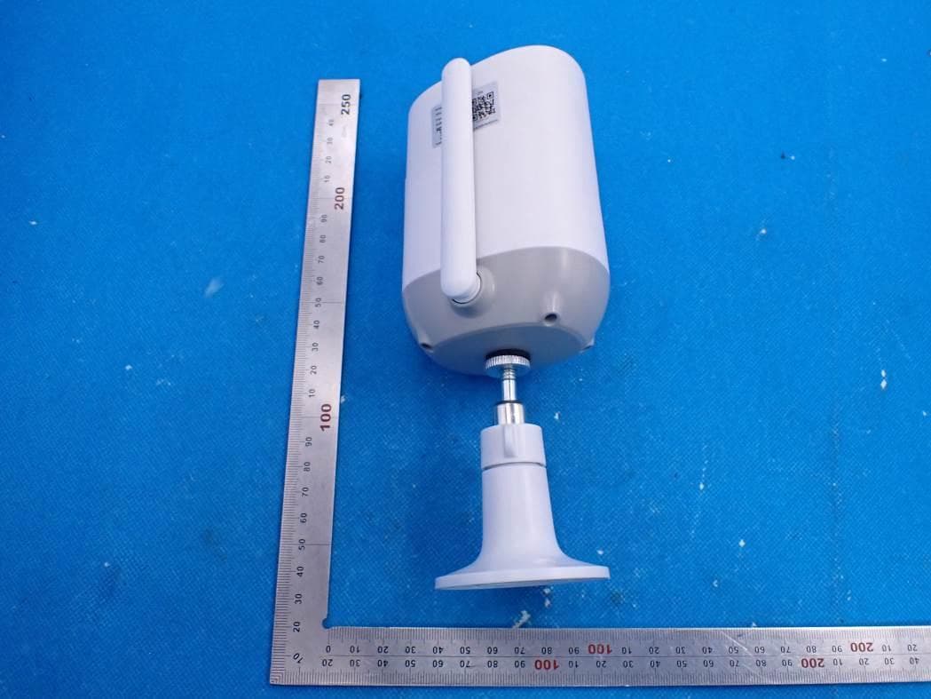
2AXBN-CG7
Aug 25, 2021Wireless Smart Battery Camera
Equipment Class
DTS - Digital Transmission System