2AXEK-GS-X032.4G WIFI Camera
SHENZHEN GENERAL TECHNOLOGY CO. ,LTD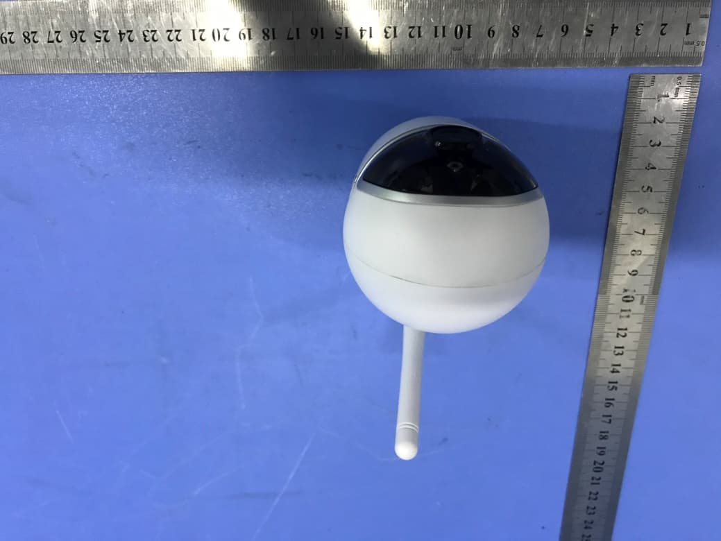
Click to zoom
Application Details
- Equipment Class
- DTS - Digital Transmission System
- Date of Grant
- Sep 03, 2020
- Application Purpose
- Original Equipment
- Date of Application
- Sep 03, 2020
- Equipment Note
- 2.4G WIFI Camera
- Frequency Range
- 2412.00000000 - 2462.00000000
- Country
- China
Documents & Files
Document Text
Text extracted from the exhibit documents filed with the FCC. Open a document above to read the original.
Users Manual
2.4G WIFI Camera Quick Setup Guide GS-X03 Please read this user's guide carefully before using the product and keep it properly ※The screen displays and illustrations in this user's guide are examples only, please refer to the actual product Product Use Turn on the Device Plug the power cable into the Micro-USB power jack on the back of the camera and wait a few seconds for the camera to automatically turn on. Voice prompt at power-on: The system is starting up, please wait. If there is no voice reminder, please restore the factory settings and try again. Note: Do not twist the head of the camera to force it to rotate after turning it on. If you need to adjust the monitoring orientation, you can adjust it through the PTZ function of the mobile APP. Restore the Factory Settings Insert the reset pin* into the reset hole and press for 5 seconds to restore the factory settings. (This operation will retain the contents of the MicroSD memory card). Quick Setup for Wi-Fi Camera Mode Download APP Account registration and login: users can register and log in via mobile phone number (currently only for Chinese mainland phone number), email (please use real email to retrieve password later), or log in with WeChat or QQ. Note: Please be sure to use your account to log in the APP, otherwise some device functions may not work properly. (Android / IOS scan code adaptive) PC Client download address http://www.p6scloud.com Add Device Method 1:QR Code Open the P6SLite APP, click ‘+’ in the upper right corner of the home page, select ‘Add Wi-Fi Device’, click ‘Next’, select ‘Please use the scan code distribution network to connect the router’, follow the page prompts for follow-up operations, and wait for the device to successfully connect to the network. Method 2:AP Hotspot Same as Method 1,select ‘Add Wi-Fi Device’, click ‘Next’, select ‘Please use the AP hotspot distribution network’, select the device hotspot, follow the page prompts for follow-up operations, and wait for the device to successfully connect to the network. QR Code AP Hotspot QR Code Connection AP Hotspot Connection View in Real Time Open the P6SLite APP, select the connected 2.4G WIFI Camera on the home page, and you can browse in real time. Through the camera's control interface, you can adjust the camera's sharpness, horizontal and vertical angles, as well as screen capture and recording, and remote calls operation, etc. Video Playback The 2.4G WIFI Camera can only use the historical video playback function after installing a MicroSD memory card. After the MicroSD memory card is installed and turned on, the camera will automatically start recording video. In the 2.4G WIFI Camera control interface, click the button ‘Playback’ to enter the historical video playback interface. You can drag the timeline to select the time period to be played back, or you can use the button ‘Date’ to select historical videos on different dates. Live Preview Playback AI Human Tracking Intelligent Automatic Care Turn on the AI ‘Human Tracking’ mode. When human beings appear on the screen, the device will automatically capture pictures, record videos, and push alarm messages to the user's mobile phone in conjunction. Note: The linkage push function needs to be turned on (P6SLite APP home page → device preview list →2.4G WIFI Camera preview → turn on ‘Arm/Disarm’ in the lower left corner). Setting Method 1. Open the P6SLite APP, enter the ‘Settings’ function page of the 2.4G WIFI Camera on the homepage, select the ‘Human Tracking’ function and turn on ‘Human Tracking Detection’; 2. Select the required trigger actions, such as SD Card Snapshot, SD Card Record, Push Notification, Alarm Sound, etc.; you can set up ‘Armed all day’ or ‘Custom arming’, you can set Sensitivity, Detection area, etc.; 3. On the device preview interface, you can use the shortcut buttons to turn off the ‘Human Tracking’ function. In addition, if you only need to detect human without tracking people, you can turn off the ‘Human Tracking’ function in the ‘Human Tracking’ function list. Video Share Open the P6SLite APP, click the ‘···’ button on the top right corner of the 2.4G WIFI Camera device preview on the homepage, and select ‘Sharing management’ to enter the sharing settings and invite others to watch. The person being shared needs to download the P6SLite APP, register an account and log in to view. Device Setting Human Tracking Quick Setup for USB Webcam Mode Installation Method The 2.4G WIFI Camera can be placed on a flat surface such as a desk, dining table, coffee table, cabinet top, etc., wherever you want to make a video calling or live chat. Video Calling Designed for the way you like to make a video call, place the 2.4G WIFI Camera where you want it and then connect the camera to a computer USB port. The Windows® UVC or Mac drivers are loaded automatically. Driver installation may take a few moments. The Webcam does not ship with video calling software. To make a video call, use the Device Sharing Sharing Setting video calling application you prefer. Precautions The proper environment temperature for this device range from -10°C to 50°C.Please avoid exposing it to too much hotter or colder environment. Please do not use this camera in somewhere moist or highly risk of getting water inside of it, thus to ensure this device of precise electronics a long service life. For better using experience, please keep the front and both sides of the camera lens away from objects reflective as glass, white wall etc. So that the picture function well without overexposure. Make sure the camera has been placed in areas of good reception of Wi-Fi signal or at lease within the signal zone. Set it up away from somewhere might jamming signal as metal or microwave oven. Warranty Description Our company will implement warranty for installation and use according to the product guide. Please send this warranty card together with the purchased product to after-sales service department when maintenance…
Text truncated - open the document above for the full version.
External Photos
Page: 3 of 11 FCC ID: 2AXEK-GS-X03 TB-RF-074-1.0 Appendix III EUT External Photographs Photo 1 Appearance of EUT Photo 2 Appearance of EUT 2.4G WIFI Antenna Page: 4 of 11 FCC ID: 2AXEK-GS-X03 TB-RF-074-1.0 Photo 3 Appearance of EUT Photo 4 Appearance of EUT Page: 5 of 11 FCC ID: 2AXEK-GS-X03 TB-RF-074-1.0 Photo 5 Appearance of EUT Photo 6 Appearance of EUT Page: 6 of 11 FCC ID: 2AXEK-GS-X03 TB-RF-074-1.0 Photo 7 Appearance of EUT
ID Label/Location Info
Page: 1 of 11 FCC ID: 2AXEK-GS-X03 TB-RF-074-1.0 Appendix IFCC ID Label Size for the label: 15mm X 20mm FCCID: 2AXEK-GS-X03 Model: GS-X03 This device complies with Part 15 of the FCC Rules. Operation is subject to the following two conditions: 1. This device may not cause harmful interference. 2. This device must accept any interference received, including interference that may cause undesired operation. Page: 2 of 11 FCC ID: 2AXEK-GS-X03 TB-RF-074-1.0 Appendix II ID Label Location ID LOCATION
Internal Photos
Page: 7 of 11 FCC ID: 2AXEK-GS-X03 TB-RF-074-1.0 Appendix IV EUT Internal Photographs Photo 8 Internal of EUT Photo 9 Internal of PCB Page: 8 of 11 FCC ID: 2AXEK-GS-X03 TB-RF-074-1.0 Photo 10 Internal of PCB Photo 11 Internal of PCB Page: 9 of 11 FCC ID: 2AXEK-GS-X03 TB-RF-074-1.0 Photo 12 Appearance of PCB
Operational Description
version01 SHENZHEN GENERAL TECHNOLOGY CO. ,LTD Declaration concerning Antenna Specification It is hereby declared that the product Model No.: GS-X03, GS-XXX ( X means digital number“0”-“9”or English letter “A”-“Z”) FCC ID: 2AXEK-GS-X03 fulfills the requirement in FCC test relating to the antenna type. The device specified above confirms to the FCC recommendations for External antenna type(s) described below: Model No. of antenna: N/A Type of antenna: 2dBi FPC Antenna Gain of the antenna: 2dBi Frequency range: 2412-2462 MHz The mounting of the antenna is fixed to the radio module and no other antenna should be used. Company name : SHENZHEN GENERAL TECHNOLOGY CO. ,LTD Address: No.5 Xiantian Road, Longgang District, Shenzhen, China City: Shenzhen ZIP / Postal code: Country: China Place: JING JING ZHANG / Vice General Manager Date: 2020-09-01 Signature:
RF Exposure Info
Report No.: TB-MPE175077 Page: 1 of 3 TB-RF-075-1.0 Maximum Permissible Exposure Evaluation FCC ID: 2AXEK-GS-X03 1. Client Information Applicant : SHENZHEN GENERAL TECHNOLOGY CO. ,LTD Address : No.5 Xiantian Road, Longgang District, Shenzhen, China Manufacturer : SHENZHEN GENERAL TECHNOLOGY CO. ,LTD Address : No.5 Xiantian Road, Longgang District, Shenzhen, China 2. General Description of EUT EUT Name : 2.4G WIFI Camera Models No. : GS-X03, GS-XXX ( X means digital number“0”-“9”or English letter “A”-“Z”) Model Different : All these models are identical in the same PCB, layout and electrical circuit, the only difference is Housing. Brand Name : ---- Product Description : Operation Frequency: 802.11b/g/n(HT20): 2412MHz~2462MHz Number of Channel: 802.11b/g/n(HT20):11 channels E.I.R.P: 802.11b: 15.25 dBm 802.11g: 15.42 dBm 802.11n (HT20): 14.57 dBm Antenna Gain: 2dBi FPC Antenna Power Rating : Adapter(XED-UL050150CU) Input: AC 100~240V, 50/60Hz 0.3A MAX Output: DC 5V, 1.5A. Software Version : V1.1.4_20200709 Hardware Version : A0 Connecting I/O Port(S) : Please refer to the User's Manual Remark : the MPE report used the EUT(TBBJ-20200807-11-2 #). Report No.: TB-MPE175077 Page: 2 of 3 TB-RF-075-1.0 MPE Calculations for WIFI 1. Antenna Gain: FPC Antenna: 2dBi. 2. EUT Operation Condition: Software provided by client enabled the EUT to transmit and receive data at lowest, middle and highest channel individually. 3. Exposure Evaluation: Equation from page 18 of OET Bulletin 65, Edition 97-01 S=(PG)/4πR 2 Where S: power density P: power input to the antenna G: power gain of the antenna in the direction of interest relative to an isotropic radiator. R: distance to the center of radiation of the antenna 4. Test Result: Worst Maximum MPE Result Mode N TX Freq. (MHz) Conducted Power(max) (dBm) Turn-up Power (dB) Max tune up power (dBm) [P] ANT Gain (dBi) [G] Distance (cm) [R] Power Density (mW/ cm 2 ) [S] 802.11b 1 2412 15.25 15±1 16 2 20 0.0125 2437 13.97 13±1 14 2 20 0.0079 2462 13.38 13±1 14 2 20 0.0079 802.11g 1 2412 15.42 15±1 16 2 20 0.0125 2437 14.08 14±1 15 2 20 0.0099 2462 13.49 13±1 14 2 20 0.0079 802.11n(HT20) 1 2412 14.57 14±1 15 2 20 0.0099 2437 13.46 13±1 14 2 20 0.0079 2462 13.47 13±1 14 2 20 0.0079 Note: (1) N TX = Number of Transmit Antennas (2) RF Output power specifies that Maximum Conducted Peak Output Power. Report No.: TB-MPE175077 Page: 3 of 3 TB-RF-075-1.0 5. Conclusion: As specified in Table 1B of 47 CFR 1.1310- Limits for Maximum Permissible Exposure (MPE), Limits for General Population/ Uncontrolled Exposure Frequency Range (MHz) Power density (mW/ cm 2 ) 300-1,500 F/1500 1,500-100,000 1.0 For 2.4WIFI:2412~2462 MHz MPE limit S: 1mW/ cm 2 The MPE is calculated as 0.0125 mW / cm 2 < limit 1mW / cm 2 . So, RF exposure limit warning or SAR test are not required. The EUT will only be used with a separation of 20cm or greater between the antenna and nearby persons and can therefore be considered a mobile transmitter per 47 CFR2.1091 (b). The RF Exposure Information page from the manual is included here for reference. Note For a more detailed features description, please refer to the RF Test Report. 6. Conclusion: The measurement results comply with the FCC Limit per 47 CFR 2.1091 for the uncontrolled RF Exposure of mobile device. -----END OF REPORT-----
Test Report
Shenzhen Toby Technology Co., Ltd. Report No.: TB-FCC175076 Page: 1 of 67 TB-RF-074-1.0 1A/F., Bldg.6, Yusheng Industrial Zone, The National Road No.107 Xixiang Section 467, Xixiang, Bao’an, Shenzhen, China Tel: +86 75526509301 Fax: +86 75526509195 FCC Radio Test Report FCC ID: 2AXEK-GS-X03 Original Grant Report No. : TB-FCC175076 Applicant : SHENZHEN GENERAL TECHNOLOGY CO. ,LTD Equipment Under Test (EUT) EUT Name : 2.4G WIFI Camera Model No. : GS-X03 Series Model No. : GS-XXX ( X means digital number“0”-“9”or English letter “A” -“Z”) Brand Name : ---- Sample ID TBBJ-20200807-11-1#& TBBJ-20200807-11-2# Receipt Date : 2020-08-24 Test Date : 2020-08-25 to 2020-08-31 Issue Date : 2020-09-01 Standards : FCC Part 15, Subpart C 15.247 Test Method : ANSI C63.10: 2013 Conclusions : PASS In the configuration tested, the EUT complied with the standards specified above, The EUT technically complies with the FCC and IC requirements Test/Witness Engineer : Jack Deng Engineer Supervisor : Ivan Su Engineer Manager : Ray Lai This report details the results of the testing carried out on one sample. The results contained in this test report do not relate to other samples of the same product. The manufacturer should ensure that all products in series production are in conformity with the product sample detailed in the report. Report No.: TB-FCC175076 Page: 2 of 67 TB-RF-074-1.0 Contents CONTENTS ............................................................................................................................................. 2 1. GENERAL INFORMATION ABOUT EUT ............................................................................. 5 1.1 Client Information ................................................................................................................. 5 1.2 General Description of EUT (Equipment Under Test) ................................................... 5 1.3 Block Diagram Showing the Configuration of System Tested ...................................... 6 1.4 Description of Support Units .............................................................................................. 6 1.5 Description of Test Mode .................................................................................................... 7 1.6 Description of Test Software Setting ................................................................................ 8 1.7 Measurement Uncertainty .................................................................................................. 9 1.8 Test Facility ........................................................................................................................... 9 2. TEST SUMMARY ..................................................................................................................... 10 3. TEST SOFTWARE ................................................................................................................... 10 4. TEST EQUIPMENT .................................................................................................................. 11 5. CONDUCTED EMISSION TEST ........................................................................................... 12 5.1 Test Standard and Limit .................................................................................................... 12 5.2 Test Setup ........................................................................................................................... 12 5.3 Test Procedure ................................................................................................................... 13 5.4 Deviation From Test Standard ......................................................................................... 13 5.5 EUT Operating Mode ........................................................................................................ 13 5.6 Test Data ............................................................................................................................. 13 6. RADIATED EMISSION TEST ................................................................................................ 14 6.1 Test Standard and Limit .................................................................................................... 14 6.2 Test Setup ........................................................................................................................... 15 6.3 Test Procedure ................................................................................................................... 16 6.4 Deviation From Test Standard ......................................................................................... 17 6.5 EUT Operating Condition ................................................................................................. 17 6.6 Test Data ............................................................................................................................. 17 7. RESTRICTED BANDS REQUIREMENT ............................................................................. 18 7.1 Test Standard and Limit .................................................................................................... 18 7.2 Test Setup ........................................................................................................................... 18 7.3 Test Procedure ................................................................................................................... 19 7.4 Deviation From Test Standard ......................................................................................... 19 7.5 EUT Operating Condition ................................................................................................. 19 7.6 Test Data ............................................................................................................................. 19 8. BANDWIDTH TEST ................................................................................................................. 2…
Text truncated - open the document above for the full version.
Contact Information
Applicant
JING JING ZHANG(Vice General Manager)
Test Firm
Shenzhen Toby Technology Co., Ltd.Ray Lai
Technical Specifications
| # | Rule Parts | Frequency Range | Power Output |
|---|---|---|---|
| 1 | 15C | 2.41 GHz - 2.46 GHz | 34.90 mW |
Other Applications from SHENZHEN GENERAL TECHNOLOGY CO. ,LTD

2AXEK-X89
Aug 13, 2024Smart Battery Camera
Equipment Class
DTS - Digital Transmission System
2AXEK-N002
Jul 21, 2024Bird Feeder Camera
Equipment Class
DTS - Digital Transmission System
2AXEK-X11B
Jun 05, 2024Smart PTZ Camera
Equipment Class
DTS - Digital Transmission System
2AXEK-X18
Mar 14, 2024IP camera
Equipment Class
DTS - Digital Transmission System
2AXEK-X88
Dec 08, 2022Smart Battery Camera
Equipment Class
DTS - Digital Transmission System