2AXH6-S-PAD01Creality Sonic Pad
Shenzhen Creality 3D Technology Co.,Ltd.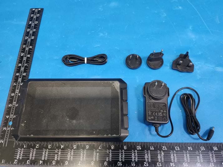
Click to zoom
Application Details
- Equipment Class
- DTS - Digital Transmission System
- Date of Grant
- Sep 24, 2022
- Application Purpose
- Original Equipment
- Date of Application
- Sep 24, 2022
- Equipment Note
- Creality Sonic Pad
- Frequency Range
- 2412.00000000 - 2462.00000000
- Country
- China
Documents & Files
Document Text
Text extracted from the exhibit documents filed with the FCC. Open a document above to read the original.
Users Manual
4. Click Connect automatically after activation, the camera will be enabled when the Creality Sonic Pad is powered on. Click to enable time lapse video, and the camera will shoot the printed model accord- ing to the set number of layers and rendering methods. After the shooting is completed, a time lapse video file will be automatically generated. Click the icon in the lower right corner to view. 5. Enter the time lapse video file storage folder, it will display the file thumbnails and print information, click the display list to enter the file management mode. 6. Enter the file management mode, you can choose to play, share, export and delete videos. 15 10. Slicing software displays previews and thumbnails 1. Ultimaker Cura 5.1.0 1.1 Add thumbnails on Ultimaker Cura 5.1.0, select "Extensions" - "Post Processing" - "Modify G-code". 1.2 After entering, select the post-processing script shown in the figure (‘’Add a script’’-’’Create Thumbnail), and a red dot will appear in the post-script prompt box next to the slice button. 1.3 After the slicing is completed, export it in ufp format and upload it using a U disk or WEB terminal. The Sonic Screen will automatically produce a sliced G-code file with a preview image. 16 2. PrusaSlicer 2.4.2 2.1 Added thumbnails and previews on PrusaSlicer 2.4.2. In “Expert” mode, you can add a custom-sized thumbnails and previews in "Printer Settings"-''Firmware'"-"G-code thumbnails". 3. SuperSlicer 2.3.5 3.1 Added thumbnails and previews on SuperSlicer 2.3.57. In expert mode, you can add custom size thumbnails and previews in "Printer Settings" - "Thumbnails" - ''Size for gcode''. 4.1 Add thumbnails and preview images on Creality Print, select "Tool" - "Manage Printer" to enter the printer management interface. 17 4.2 In the printer management interface, check "Generate preview", and select the preview image size to add a preview image of a custom size. 1. Printer Firmware Compilation Please download the firmware compilation guide on the official website: https://www.creality.com/pages/download For firmware compilation environment construction, please refer to the video tutorial: https://www.creality.com/pages/download 2. User-defined printer usage process 2.1 Refer to the "User-defined Printer Firmware Compilation Guide", compile the firmware and write the configuration file by yourself. After the preparation is complete, when you select a printer by One-touch change, select another printer. 11. Adaptation of other printers Ecosystem Ecosystem 18 2.2 The printer needs to flash the self-compiled firmware first, then save the corresponding configuration file Printer.cfg into the USB drive, insert the Creality Sonic Pad, and click Next step. 2.3 After the configuration file is detected, click Loaded to load the configuration file. 2.4 At this point, a pop-up window will prompt you to ensure that the printer firmware has been flashed and connected to the machine. 19 2.5 Make sure the printer firmware has been flashed and connected to the machine, click OK, Creality Sonic Pad will load the configuration file and prompt for self-test. 2.6 Click Start self-test to enter the self-test process. For the self-test process, please refer to the self-test process of “First Use” to guide the installation. 12. The use of WEB operation terminal 1. Obtaining the IP address of the Creality Sonic Pad Enter "Configure - Network Settings - Wireless Network/Wired Net- work" to obtain the current LAN IP address of the Creality Sonic Pad. 2. Obtaining the serial number (DN number) of the Creality Sonic Pad screen. 20 3. Open the web browser console. Make sure that the PC and the Creality Sonic Pad are in the same local area network, enter the obtained IP address of the Creality Sonic Pad into the browser, or the local area network domain name spad-DN.lo- cal(DN is the first four digits of the screen DN number). (Example: http://172.23.214.236 or http://spad-8888.local) 13. FAQ Please visit the official website for more solutions to common problems: https://www.creality.com/pages/faq?spm=..page_1934 481.header_1.1 Ecosystem 1. Check whether the network is normal, and the upgrade package can be downloaded only if the network is normal; 2. If it prompts "download failed" when the network is normal, please check whether the storage of Creality Sonic Pad is more than 500MB. If the storage is insufficient, please try to clean up some of the slice files or time-lapse video files to ensure that the available space is more than 500MB before trying to upgrade. 3. If it still prompted with "upgrade failed" when the network is normal and the available storage is sufficient, please contact the after-sales service. Failed to upgrade online 21 Printed model with poor edge quality. What are the appropriate acceleration and speed settings when slicing? 1.Check that the printer is properly connected to the Creality Sonic Pad. 2.Check whether the power connection of the Creality Sonic Pad and the printer is normal. Abort printing during printing 1. Enter configuration-camera to see if there is a real-time image, if there is no real-time image, it should be turned on first; 2. Confirm that the camera is a general-purpose USB camera, and the real-time screen has been turned on; 3. Enter Configure - Local Information to check whether the available storage is insufficient; 4. Check whether the time-lapse video has been turned on and whether the frequency of the time-lapse video is set correctly. (the frequency should be less than the number of slice layers) Time-lapse photography did not shoot successfully The vibration sensor should be installed on the hotend . You can print the bracket which the model file provided by Creality, and then use the screws to fasten the sensor to the bracket without direction requirement. Where should the vibration sensor be placed when resonance compensation is automatically detected? Are there any orientation requirements ? You can refer to the slicing software configurat…
Text truncated - open the document above for the full version.
Users Manual
2.7.4 打开打印机电源后,Creality Sonic Pad将自动连接打印机(打印机开机 后会将SD/TF中的固件自动刷入)。 2.7.5 打印机固件刷写完成,点击重启。 3. 功能自检 打印机固件刷写完成后,Creality Sonic Pad会自动重启打印机,重启后进 入功能自检,按照屏幕指示进行操作。自检完成后,点击立即体验,屏幕将会 保存相关的用户配置,并重载系统,进入主页面后,即可开始使用本产品。 06 六. 日常使用 1. 打印 1.1 进入主页面,点击“ 打印”。 1.2 选择本地或U盘中保存的gcode文件,点击 打印此文件。 1.3 进入打印界面,打印机开始工作,界面中会显示预计时间等打印信息。 1.4 打印过程中可调整参数,具体参数如图所示。 注意:参数调整只有在打印机正式开 始打印后才能进行调整,准备过程中 (如加热中)无法调整 。 07 1.5 打印过程中可选择暂停/停止打印,暂停后可继续打印,停止打印则会退出 打印界面,进入主界面。 1.7 急停后Creality Sonic Pad会跳到如下界面,需要手动点击重启图标恢复连 接。 1.6 打印过程中如需立即停止工作,可点击 。 2. 切片文件管理 2.1 进入gcode选择界面,可进行以下操作。 管理gcode文件,U盘和本地文件可以相互复制及删除。 可选择文件排序类型。 模型预览区域可查看切片文件详情。 点击 可以直接打印此gcode文件。 A B C D 08 AB DC 09 七. 系统升级 1. 在线升级 1.1 在首页页面,依次进入“配置”——“其他设置”,查看系统是否有新版本发布。 2. U盘升级 2.1 请到 https://www.creality.com/pages/download Ecosystem 下载对 应的升级文件,解压后复制至U盘根目录,插入本机后会自动弹出升级提示,按 引导升级。 1.2 点击系统升级,按屏幕提示操作,升级完成后,系统会自动重启。 10 1. 显示宏 点击 按钮可显示/隐藏宏功能(左侧栏和控制界面内)。 2. 命令行 点击 按钮可显示/隐藏命令行。 3. PID喷头检测 点击进入检测页面,设置喷头检测温度后,点击开始检测,根据提示确认检测完 毕后,系统会自动保存。 八. 高级设置 4. PID热床检测 点击进入检测页面,需要设置热床检测温度后,点击开始检测,根据提示确认检 测完毕后,系统会自动保存。 11 5.振动补偿 进入配置,高级设置,点击振动补偿。 5.2 连接传感器并安装完毕后,点击下一步,进入检测页面。 5.1 进入振动补偿页面,按图所示连接传感器和安装传感器。 12 5.4 检测完毕后,点击检测完成,退出检测页面。保存配置后,Creality Sonic Pad将重启。 5.3 点击开始检测,打印机将归零,然后进行自动检测。 6. 自动检测 自检项可自由选择,选取后,点击开始检测,跟随引导即可完成检测,完成后 需要保存配置。 7. 屏幕翻转 点击确定,屏幕将翻转180°。 8. 获取硬件串口ID 点击获取,获取主板串口ID,用于自定义机型参数设置。 13 九. 延时摄影 1. 在关机状态下,将摄像头连接到Creality Sonic Pad USB接口,进入配置页 面点击摄像头。 2. 进入摄像头页面,点击摄像头图标,勾选连接摄像头。 3. 点击此页面右下角的 标志,进入设置页面。 14 4. 点击启动后自动连接,摄像头会在Creality Sonic Pad开机时启用,点击启用 延时摄影,摄像头工作时,将对打印的模型按照设置的层数和渲染方式进行拍 摄,拍摄完毕后会生成延时摄影文件,点击右下角 图标进入查看。 5. 进入延时摄影文件存放文件夹,展示文件缩略图和打印信息,点击展示列表 可进入文件管理模式。 6. 进入文件管理模式,可选择播放,分享,导出,删除视频。 15 十. 切片软件显示预览图和缩略图 1. Ultimaker Cura 5.1.0 1.1添加缩略图,选择“扩展”-“后期处理”-“修改G-code。 1.2 按图所示添加后期处理脚本,成功后脚本提示框会出现红点提示。 1.3 切片完成后,以ufp格式导出,使用U盘或WEB端上传Creality Sonic Pad 将自动生产带预览图的切片G-code文件。 2. PrusaSlicer 2.4.2 2.1 添加缩略图和预览图,在“打印机设置”中修改“G代码缩略图”大小,即可添 加自定义大小的缩略图和预览图。 16 3. SuperSlicer 2.3.5 3.1 添加缩略图和预览图,在“打印机设置”中修改 “缩略图大小”,即可添加自 定义大小的缩略图和预览图。 4. Creality Print 4.1 添加缩略图和预览图,选择“工具”-“管理打印机”,进入打印机管理界面。 17 1. 打印机固件编译 请在官网下载固件编译指导文件: https://www.creality.com/pages/download 固件编译环境搭建可参考视频教程: https://www.creality.com/pages/download 2. 自定义机型使用流程 2.1参照《自定义机型固件编译指导书》,自行编译固件和编写配置文件,准备 完毕后,一键换机选择机型时,选择其他机型。 4.2 打印机管理界面勾选“是否生成预览图”,并选择预览图大小,即可添加自 定义大小的预览图。 2.2 打印机需先烧录好自行编译的固件,然后将对应的配置文件Printer.cfg 存 入U盘并插入Creality Sonic Pad,点击下一步。 十一. 自定义机型适配 Ecosystem Ecosystem 18 2.3 检测到配置文件后,点击下一步即可载入配置文件。 2.4 此时弹窗提示确保打印机固件已刷好并与本机连接。 2.5 确保打印机固件已刷好并与本机连接,点击确认,Creality Sonic Pad将载 入配置文件并提示自检。 2.6 点击确定进入自检,自检流程请参照“首次使用”引导安装自检流程。 19 3.开启WEB操作端 确定PC和Creality Sonic Pad在同一局域网的情况下,将获取到的IP地址输入 到浏览器,或使用局域网域名spad-DN.local,DN为屏幕DN号前四位。 (示例:http://172.23.214.236或http://spad-8888.local) 十二. WEB操作端的使用 1. 获取Creality Sonic Pad IP地址 进入”配置-网络设置-无线网络/有线网络”,获取Creality Sonic Pad当前局域 网IP地址。 2. 获取Creality Sonic Pad序列号(DN号) 20 21 为什么打印的模型边缘质量不好?切片时加速度、速度设置多少合适? 十三. FAQ 请登录官网查看更多常见问题的解决办法: https://www.creality.com/pages/faq?spm=..page_1934481.header_1.1 Ecosys- tem 1. 检查网络是否正常,需要保证网络正常才可下载升级包; 2. 网络正常的情况下如果提示“下载失败”,请查看本机是否有大于500MB空间,如空间不足,应尝试清理 部分切片文件或延时摄影视频文件保证可用空间大于500MB再尝试升级; 3.网络正常且可用空间足够时若还提示“升级失败”,需联系售后处理。 为什么会出现在线升级失败? 1.检查打印机与Creality Sonic Pad连接是否正常; 2.检查Creality Sonic Pad和打印机电源连接是否正常。 打印过程中终止打印? 1. 进入配置-摄像头查看是否有实时画面,如无画面应先开启; 2. 确认摄像头为通用摄像头,并已打开实时画面; 3. 进入配置-本机信息查看本机容量是否不足; 4. 检查是否已开启延时摄影,延时摄影拍摄频率是否设置正确(频率应小于切片层数)。 延时摄影为什么没有拍摄成功? 振动传感器应该安装于打印喷头上,可以使用我司提供的模型文件打印支架,然后使用螺丝紧固于支架 上,无方向要求。 谐振补偿自动侦测时,振动传感器应该安装在什么位置?有无方向要求? 可参考我司提供的切片软件配置参数,默认支持的机型(Ender-3 V2 / Ender-3 S1 / Ender-3 S1 Pro)可直接在切片软件中导入对应的参数配置文件。 配置文件中添加 [filament_switch_sensor filament_sensor] pause_on_runout: true switch_pin: ^!PC15 注意!switch_pin需要确认为断料检测器连接PIN。 怎么配置文件才能兼容断料检测功能? 1.检查U盘是否正常,将U盘插入电脑,尝试修复U盘文件系统或格式化,或更换U盘重试; 2.检查USB接口是否正常,换其它USB接口尝试; 3.如采用读卡器方式,请尝试更换读卡器(或者存储卡)来判断功能是否正常。 为什么U盘读取异常? 22 1.检查打印机是否通电; 2.检查打印机固件是否为正确的版本; 3.检查配置文件是否正确匹配; 4.检查USB连接是否正常; 5.检查当前Creality Sonic Pad软件版本是否为最新版本。 为什么一直无法成功连接打印机? 1.检查X,Y轴电机是否正常,皮带是否松动; 2.确认切片打印速度和加速度是否超过打印机正常范围,适当调整打印速度和加速度(可参考我司提供的 切片参数)。 为什么打印错层? 需要确认切片文件相关参数(是否启用回抽,回抽距离,回抽速度,打印速度等)与连接的打印机机型是 否匹配,如不匹配需要重新调整参数并重新切片。 为什么打印时拉丝严重? 1. 可尝试搜索其他WIFI并尝试连接,确认是否可以正常连接;当前设备支持WPA2的加密方式,不支持 WPA3,且只支持2.4G频段; 2. 检查密码正确性,检查路由器是否正常。 为什么无法连接WIFI网络? 1.fluidd下载:PC浏览器打开设备WEB页(参照使用说明),在延时摄影菜单下下载; 2.U盘下载:插入U盘后,在配置-摄像头-延时摄影视频-视频详情页面点“导出”按钮,导出视频文件到U 盘,再从U盘复制到PC上。 如何将延时摄影文件传输到PC上? 1.Creality Sonic Pad默认开机加载摄像头设备;如果在开机后再插入摄像头,选中摄像头并选择启用 后,摄像头显示已启用,等待2分钟方可出现画面(有时需要再切换一下页面),或插入摄像头后重启 Creality Sonic Pad后可出现画面; 2.某些摄像头是定制化摄像头,未采用YUV和Mjpeg格式输出,可尝试更换摄像头再使用; 3.拔出摄像头改用U盘查看USB是否正常,如不正常请联系售后处理。 为什么我的摄像头连接上之后无法正常使用? 请参考我司提供的打印机适配指引链接。 针对非默认机型如何编译固件及修改配置文件? 开机引导或一键换机选择机型时应根据实际状况选择,主板版本需拆机查看,Ender-3 V2机型的四种选择对 应关系; a.[机型图左上角CR Touch标志]Ender-3 V2 (V4.3.1或V4.2.2) : 对应已安装CR Touch的机型,主板版本为 V4.3.1或V4.2.2 b.Ender-3 V2 (V4.3.1或V4.2.2) : 对应未安装CR Touch的机型,主板版本为V4.3.1或V4.2.2 c.Ender-3 V2 (V4.2.7) : 对应未安装CR Touch的机型,主板版本为V4.2.7 d.[机型图左上角CR Touch标志]Ender-3 V2 (V4.2.7) : 对应已安装CR Touch的机型,主板版本为V4.2.7 开机引导或一键换机时Ender3 V2机型无法连接如何处理? 23 请将文件存于U盘,插入Creality Sonic Pad USB接口,便可读取到相应文件。 为什么把SD卡插入打印机,在Creality Sonic Pad找不到对应文件? 24 中国制造 加入Facebook社区 https://www.facebook.com/groups/sonicpad 400-6133 882 [email protected]
Cover Letter(s)
Shenzhen Creality 3D Technology Co., Ltd. Authorization Company: Shenzhen Creality 3D Technology Co., Ltd. Address: 18F, JinXiuHongDu Building, Meilong Blvd., Longhua Dist., Shenzhen, China 518131 Product Name: Creality Sonic Pad Trademark: Model Number(s): S-Pad 01 We authorize MiCOM Labs Inc., 575 Boulder Court, Pleasanton, California 94566, USA, to act on our behalf on all matters concerning the certification of above named equipment. We declare that MiCOM Labs Inc. is allowed to forward all information related to the approval and certification of equipment to the regulatory agencies as required and to discuss any issues concerning the approval application. Any and all acts carried out by MiCOM Labs on our behalf shall have the same effect as acts of our own. Signature: Date: 2022/09/05 Name: Lucy Li Title: Safety enginner Company: Shenzhen Creality 3D Technology Co.,Ltd.
Cover Letter(s)
Shenzhen Creality 3D Technology Co., Ltd. Office of Engineering Technology Federal Communications Commission 7435 Oakland Mills Road Columbia, MD 21046 USA Date: 2022/09/05 Subject; Request for Confidentiality FCC ID: 2AXH6-S-PAD01 To Whom It May Concern, Pursuant to the provisions of the Commission’s rules Title 47 Sections §0.457 and §0.459, we are requesting the Commission to withhold the following attachment(s) as confidential documents from public disclosure indefinitely. These documents contain detailed system and equipment descriptions and are considered as proprietary information in operation of the equipment. The public disclosure of these documents might be harmful to our company and would give competitors an unfair advantage in the market. Schematic Diagram Block Diagram Operational Description In additional to above mentioned documents, in order to comply with the marketing regulations in Title 47 CFR §2.803 and the importation rules in Title 47 CFR §2.1204, while ensuring that business sensitive information remains confidential until the actual marketing of newly authorized devices, we request Short Term Confidentiality of the following attachment(s); User Manual For 45 days, pursuant to Public Notice DA 04-1705. OR For 180 days pursuantto KDB 726920 D01. It is our understanding that all measurement test reports, FCC ID label format and correspondence during the certification review process cannot be granted as confidential documents and this information will be available for public review once the grant of equipment authorization is issued. Sincerely, Signature: Name: Lucy Li Title: Safety enginner
External Photos
EUT EXTERNAL PHOTOGRAPHS EUT View 1 EUT View 2 EUT View 3 EUT View 4 EUT View 5 EUT View 6 EUT View 7 ----------------The end----------------
ID Label/Location Info
Long*Width: 120(cm)*40(CM) FCC ID: 2AXH6-S-PAD01
Internal Photos
EUT INTERNAL PHOTOGRAPHS EUT Housing and Board View 1 EUT Housing and Board View 2 EUT Housing and Board View 3 EUT Housing and Board View 4 EUT Housing and Board View 5 EUT Housing and Board View 6 EUT Housing and Board View 7 EUT Housing and Board View 8 EUT Housing and Board View 9 EUT Housing and Board View 10 EUT Housing and Board View 11 EUT Housing and Board View 12 EUT Housing and Board View 13 EUT Housing and Board View 14 ----------------The end---------------- Antenna
RF Exposure Info
FCC ID: 2AXH6-S-PAD01 RF exposure evaluation According to§15.247(i), §1.1307 and KDB447498, systems operating under the provisions of this section shall be operated in a manner that ensures that the public is not exposed to radio frequency energy level in excess of the commission’s guidance. General frequency and separation-distance dependent MPE-based effective radiated power (ERP) thresholds are in Table B.1 [Table 1 of §1.1307(b)(1)(i)(C)] to support an exemption from further evaluation from 300 kHz through 100 GHz. For mobile devices that are not exempt per Table B.1 [Table 1 of §1.1307(b)(1)(i)(C)] at distances from 20 cm to 40 cm and in 0.3 GHz to 6 GHz, evaluation of compliance with the exposure limits in §1.1310 is necessary if the ERP of the device is greater than ERP20cm in Formula (B.1) [repeated from §2.1091(c)(1); also in §1.1307(b)(1)(i)(B)]. According to FCC Part 2.1091 and § 1.1307(b)(3)(i)(C) , this unlicensed transmitting devices is categorically excluded from routine environmental evaluation for RF exposure prior to equipment authorization or use, According to the KDB 447498 , the simple calculation as below: WIFI The source-based ERP = 17.51dBm = 56.36 mW The MPE limit is 19.2R 2 (768mW) for general population and uncontrolled exposure in the 2.4GHz frequency range according to FCC Part 1.1307(b)(3)(i)(C). As the measured power density at 20cm from the transmitter is lower than the MPE limit, the compliance to the MPE limit can be ensured by indicating the minimum 20cm separation between the transmitter's radiating structure and body of the user or nearby persons.
Test Report
ShenzhenLejinradiofrequencytechnologyCo.,LTD LejinradiofrequencyProprietary&Confidential©2017LejinradiofrequencyCorporation.Allrightsreserved. Add:Rm301B,A4Bld,JunfengInnovationPark,Fuyong,BaoanDist,Shenzhen.Tel:0755-27780515Email:[email protected] SPECIFICATIONSFORAPPROVAL CustomerName:ShenzhenCreality3DTechnologyCo.,LTD ProductName:WIFIAntenna ProductModel:SONIC-L PartNumber:LJF02-22060908-R1A WriteBy:Huxuwen IssuedDate:2022-06-09 CUSTOMER ENGINEERR&DDEPTBUSSINESSDEPTAPPROVAL LEJIN R&DDEPTENGINEERDEPTAPPROVAL REVMODIFIEDDESCRIPTIONDATEREMARK V1.0InitialDraftRelease2022/06/09 V1.1Revisethelengthofcable2022/07/28 ShenzhenLejinradiofrequencytechnologyCo.,LTD LejinradiofrequencyProprietary&Confidential©2017LejinradiofrequencyCorporation.Allrightsreserved. Add:Rm301B,A4Bld,JunfengInnovationPark,Fuyong,BaoanDist,Shenzhen.Tel:0755-27780515Email:[email protected] Index 1.Cover ································ 1 2.Index································2 3.ProductSpecification ·························· 3 4.TestEquipment&Conditions·······················3 5.TestReport ······························ 4 6.ReliabilityTest····························5 7.Assembletype ···························· 6 8.ProductDrawing···························7 ShenzhenLejinradiofrequencytechnologyCo.,LTD LejinradiofrequencyProprietary&Confidential©2017LejinradiofrequencyCorporation.Allrightsreserved. Add:Rm301B,A4Bld,JunfengInnovationPark,Fuyong,BaoanDist,Shenzhen.Tel:0755-27780515Email:[email protected] 3.ProductSpecification A.ElectricalCharacteristics Frequency2400MHz~2500MHz VSWR<2.0 Efficiency≥40% Impedance50Ohm PolarizationLinear Gain(2.4GHz) ≤ 2.0dB B.Material&MechanicalCharacteristics MaterialofRadiatorFPC(Black),LJWF27BF CableTypeΦ1.13mm,L70mm,Black ConnectorTypeIPX1 Dimension26.0*18.8mm C.Environmental OperationTemperature-20 ̊C~+70 ̊C StorageTemperature-30 ̊C~+85 ̊C Humidity40%~95% 4.TestEquipment&Conditions 1.NetworkAnalyzersAgilent8753D/5071C 2.HSPAandLTEprotocoltestsetR&SCMW500-PT 3.CommunicationsTestSetAgilent8960 4.3DChamberTestSystem Chart1Testtopology ShenzhenLejinradiofrequencytechnologyCo.,LTD LejinradiofrequencyProprietary&Confidential©2017LejinradiofrequencyCorporation.Allrightsreserved. Add:Rm301B,A4Bld,JunfengInnovationPark,Fuyong,BaoanDist,Shenzhen.Tel:0755-27780515Email:[email protected] 5.TestReport 5.1VoltageStandingWaveRatio(VSWR). Chart2VSWR 5.2Efficientandgain. 5.3Radiationpattern. ShenzhenLejinradiofrequencytechnologyCo.,LTD LejinradiofrequencyProprietary&Confidential©2017LejinradiofrequencyCorporation.Allrightsreserved. Add:Rm301B,A4Bld,JunfengInnovationPark,Fuyong,BaoanDist,Shenzhen.Tel:0755-27780515Email:[email protected] 6. ReliabilityTest TestItemTestconditionEquipmentSpecificationResult 1 LowTemp. Storage Test Temperature:-30°C,Time:48hrs Testcondition:PlacingantennainaLow/High TemperatureChamber,keepthetempis25°Candhumidityis 65%foronehour,thenstep-downthetemp.to-30°Cinone hour,storeantennafor44hours;step-uptempto25°C,test antennaafter2hours. Temp.&Hum i. Tester Nomaterial deformationis allowed. Electronic Performanceis ok. PASS 2 High Temp./High Humid StorageTest Temperature:85°CHumidity:85%RHTime:48hrs Testcondition:PlacingantennainaLow/High TemperatureChamber,keepthetempis25°Candhumidityis 65%foronehour,thenstep-upthetemp.to80°Candthe humidityupto85%inonehour,storeantennafor44hours; step-downtempto25°C,testantennaafter2hours. Temp.&Hum i. Tester Nomaterial deformationis allowed. Electronic Performanceis ok. PASS 3 Salt-Spray6 prayTest PlacingantennaintheSalt-SprayTester,setthetest condition,Temp:35±2°CHumidity:85%NaClsaltspray:5 ±1%.PHvalue:6.5~7.2Testtime:24hours Salt-Spray Tester Nocolorchange Noappear rusting PASS 7.Assembletype ShenzhenLejinradiofrequencytechnologyCo.,LTD LejinradiofrequencyProprietary&Confidential©2017LejinradiofrequencyCorporation.Allrightsreserved. Add:Rm301B,A4Bld,JunfengInnovationPark,Fuyong,BaoanDist,Shenzhen.Tel:0755-27780515Email:[email protected] Chart3SONIC-Lassembletype 8.ProductDrawing Cr eatit y 3D Remark: 1.FPC material:Electrolytic copper.2.Backing in behind:3M300LSE. 3.Tolerance : Cuting die:±0.1mm;Circuit on FPC:±0.05mm ; others are ±0.05mm. 7 0 LJF02-2206090 8 -R 1 A .0±2.0mm 4.ROHS:(Pb,Hg,Cr+6,PBBs,PBDEs),<1000ppm; Cd,<100ppm. 1.0 1.8 1. 7 Φ 1.13 coaxial cable,black, KCC-1 connector WIFI ANT SO NI C-L Reviserecord 202 2 - 07 - 28 D E
Test Report
No.:BCTC/RF-EMC-005 Page: 1 of 65 Edition:A.4 TEST REPORT Shenzhen BCTC Testing Co., Ltd. Report No.: BCTC2209875128E Applicant: Shenzhen Creality 3D Technology Co., Ltd. Product Name: Creality Sonic Pad Model/Type reference: S-Pad 01 Tested Date: 2022-08-28 to 2022-09-05 Issued Date: 2022-09-19 Report No.: BCTC2209875128E No.:BCTC/RF-EMC-005 Page: 2 of 65 Edition:A.4 FCC ID: 2AXH6-S-PAD01 The test report is effective only with both signature and specialized stamp. This result(s) shown in this report refer only to the sample(s) tested. Without written approval of Shenzhen BCTC Testing Co., Ltd, this report can’t be reproduced except in full. The tested sample(s) and the sample information are provided by the client. Product Name: Creality Sonic Pad Trademark: Model/Type reference: S-Pad 01 Prepared For: Shenzhen Creality 3D Technology Co., Ltd. Address: 18F, JinXiuHongDu Building, Meilong Blvd., Longhua Dist., Shenzhen,China 518131 Manufacturer: Shenzhen Creality 3D Technology Co., Ltd. Address: Factory No.156,Huawang Road, Langkou Community, Dalang Street, Longhua District, Shenzhen, China 518131 Prepared By: Shenzhen BCTC Testing Co., Ltd. Address: 1-2/F., Building B, Pengzhou Industrial Park, No.158, Fuyuan 1st Road, Tangwei, Fuhai Subdistrict, Bao'an District, Shenzhen, Guangdong, China Sample Received Date: 2022-08-26 Sample tested Date: 2022-08-28 to 2022-09-05 Report No.: BCTC2209875128E Test Standards: FCC Part15.247 ANSI C63.10-2013 Test Results: PASS Remark: This is WIFI-2.4GHz band radio test report. Tested by: Approved by: Brave Zeng/ Project Handler Zero Zhou/Reviewer Report No.: BCTC2209875128E No.:BCTC/RF-EMC-005 Page: 3 of 65 Edition:A.4 Table of Content Test Report Declaration Page 1. Version .................................................................................................................. 5 2. Test Summary ....................................................................................................... 6 3. Measurement Uncertainty ..................................................................................... 7 4. Product Information and Test Setup ...................................................................... 8 4.2 Test Setup Configuration ...................................................................................... 9 4.3 Support Equipment ............................................................................................... 9 4.4 Channel List ........................................................................................................ 10 4.5 Test Mode ........................................................................................................... 10 4.6 Table Of Parameters Of Text Software Setting ................................................... 10 5. Test Facility And Test Instrument Used ............................................................... 11 5.1 Test Facility ......................................................................................................... 11 5.2 Test Instrument Used .......................................................................................... 11 6. Conducted Emissions .......................................................................................... 13 6.1 Block Diagram Of Test Setup .............................................................................. 13 6.2 Limit .................................................................................................................... 13 6.3 Test procedure .................................................................................................... 13 6.4 EUT operating Conditions ................................................................................... 13 6.5 Test Result .......................................................................................................... 14 7. Radiated Emissions ............................................................................................. 16 7.1 Block Diagram Of Test Setup .............................................................................. 16 7.2 Limit .................................................................................................................... 17 7.3 Test procedure .................................................................................................... 18 7.4 EUT Operating Conditions .................................................................................. 19 7.5 Test Result .......................................................................................................... 19 8. Radiated Band Emission Measurement and Restricted Bands Of Operation ...... 25 8.1 Block Diagram Of Test Setup .............................................................................. 25 8.2 Limit .................................................................................................................... 25 8.3 Test procedure .................................................................................................... 26 8.4 EUT Operating Conditions .................................................................................. 26 8.5 Test Result .......................................................................................................... 27 9. Power Spectral Density Test ............................................................................... 29 9.1 Block Diagram Of Test Setup .............................................................................. 29 9.2 Limit .................................................................................................................... 29 9.3 Test procedure .................................................................................................... 29 9.4 EUT Operating Conditions .................................................................................. 29 9.5 Test Result ..............................................................................................…
Text truncated - open the document above for the full version.
Test Setup Photos
TEST SETUP PHOTOGRAPHS 1.1. Photos of Conducted Emission Measurement 1.2. Photos of Radiation Emission Measurement Spurious Emission Test Setup (Between 30MHz – 1GHz) Spurious Emission Test Setup (above 1GHz) ----------------The end----------------
Contact Information
Applicant
Lucy Li(Safety enginner)
Technical Contact
Test Firm
Shenzhen BCTC Testing Co., Ltd.Sally He
[email protected]15999690624
Technical Specifications
| # | Rule Parts | Frequency Range | Power Output |
|---|---|---|---|
| 1 | 15C | 2.41 GHz - 2.46 GHz | 60.00 mW |
Other Applications from Shenzhen Creality 3D Technology Co.,Ltd.
2AXH6-CFSEVO
Jul 02, 2026Filament Management System
Equipment Class
DXX - Part 15 Low Power Communication Device Transmitter2AXH6-CRS14SP1
Apr 01, 2026Creality Sermoon P1
Equipment Class
NII - Unlicensed National Information Infrastructure TX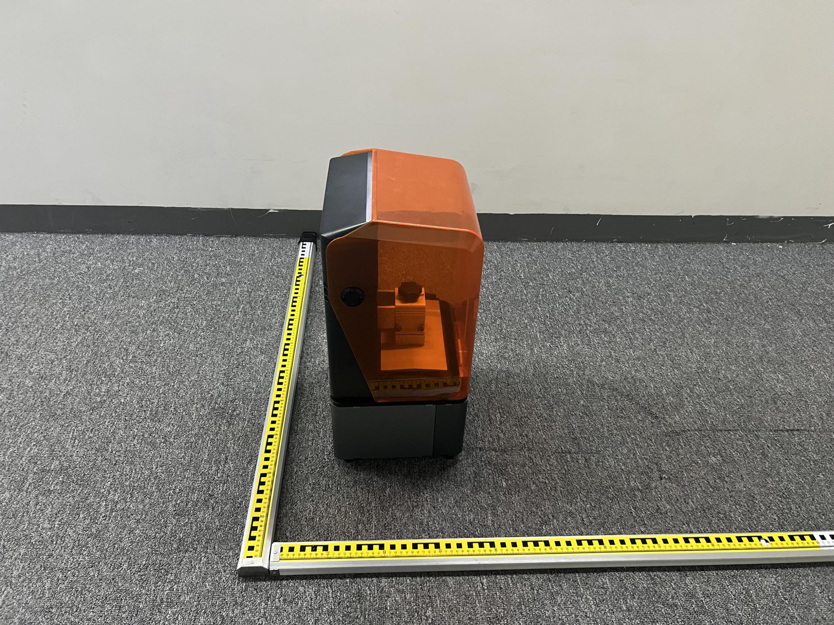
2AXH6-SKY2025
Mar 20, 20263D Printer
Equipment Class
NII - Unlicensed National Information Infrastructure TX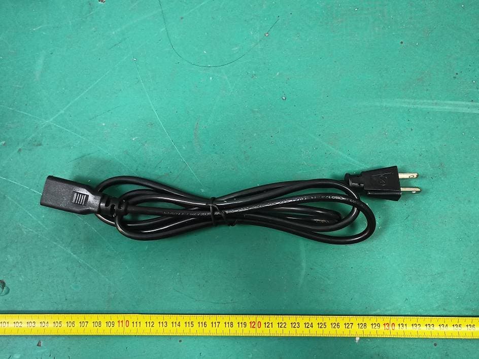
2AXH6-I7
Dec 15, 20253D Printer
Equipment Class
DTS - Digital Transmission System
2AXH6-CFSLITE
Dec 15, 2025Filament Management System
Equipment Class
DXX - Part 15 Low Power Communication Device Transmitter