FCCID.CO- FCC ID Database
HomeCompaniesEquipment ClassesSearch

© 2026 FCC ID Database. All rights reserved.

AboutContactData sourced from FCC public records
  1. Home/
  2. Generation-S Private Limited/
  3. 2AXKN-TOUR

2AXKN-TOURTOUR TRUE WIRELESS IN EAR MONITORS

Generation-S Private Limited
TOUR TRUE WIRELESS IN EAR MONITORS - FCC ID 2AXKN-TOUR - Generation-S Private Limited
Click to zoom

Application Details

Equipment Class
DTS - Digital Transmission System
Date of Grant
Oct 07, 2020
Application Purpose
Original Equipment
Date of Application
Oct 07, 2020
Equipment Note
TOUR TRUE WIRELESS IN EAR MONITORS
Frequency Range
2402.00000000 - 2480.00000000
Company
Generation-S Private Limited
Country
Singapore

Documents & Files

Select a file to view
Users Manual

↗

Cover Letter(s)

↗
↗

External Photos

↗

ID Label/Location Info

↗

Internal Photos

↗

RF Exposure Info

↗

Test Report

↗
↗
↗
↗

Test Setup Photos

↗

Document Text

Text extracted from the exhibit documents filed with the FCC. Open a document above to read the original.

Users Manual

TR UE WIRELESS IN EAR MONITORS QUI CK START In t he box Product overview Pairing Fit Charging Fender® TWS APP D ETAILS T urning On/Off Tap Controls – Music & Calls Troubleshooting Specifications Care and maintenance Safety Waterproof Warranty I N THE BOX P RODUCT OVERVIEW P AIRING T o pair to a Bluetooth audio device 1,S tart with the TWS inside the charging case with the lid closed. 2,Open the charging case, press and hold the case button until the LED on the charging case blinks blue and green,the TWS LED blinks green. 3,On your Bluetooth audio device, go to Bluetooth settings and select “Fender Tour L”. Once connected, the TWS LED will turn o ff. F IT • Y our Fender Tour TWS come factory fitted with S/M/L three sized tips. • Fit the TWS snugly within your ears so that they are completely sealed. • To achieve the most comfortable fit and sound for your TWS, take time to test out the various tip sizes to find the best fitting size. It is normal to use differently sized tips in each ear. CHA RGING – TWS · T he Fender® Tour is capable of 5 hours of playback when fully charged. The charging case gives you 4 additional recharge cycles or 20 hours additional playback.* · T he TWS will start charging once they are placed into the charging case and the lid closed. The charging case LED will indicate the charging status:  C harging: Solid red light on case.  F ully charged: Solid green light on case. · Q uick-charge feature: A 15 minute charge will provide up to 1 hour of playback*. A full charge of the earbuds can take up to 2 hours when charging from a discharged state. *The specifications are acquired from laboratory tested data. The playback time, tested under the laboratory condition of AAC format and 50% volume, may vary with different device setting, environments, usage and other factors. CHA RGING - CASE • Clo se the lid and attach the USB-C charging cable to the charging case. • The case LED will indicate the charging status: • L ED is solid red = Charging • LED is solid green = Fully charged • F ender® TWS APP T he Fender® TWS App lets you do the following: • Customize the sound profile of your Tour TWS. • Update your earbuds when new features and improvements are available. D ETAILS – Turning ON / OFF A UTO POWER ON/OFF · T urn OFF - Placing your earbuds into the charging case will automatically turn them off. Turn ON - Opening the charging case will automatically turn them on. · The TWS will automatically power off after 15 minutes when not in use. D ETAILS – Controls: Music & Calls T ROUBLESHOOTING • S oft reset: If your TWS are not responding or connecting intermittently, place them in the charging case, close the lid for at least 5 seconds and plug the case into charge. This will turn the TWS off and perform a soft reset. • Factory reset: If that does not resolve the issue, we recommend resetting the TWS to their original factory settings. Before starting this process please “FORGET” or “REMOVE” your Fender® Tour device from the Bluetooth menu on all your connected audio devices. • Pla ce both TWS in the charging case and close the lid. • Open the charging case, press & hold the case button until the case LED starts blinking green (about 8- 12 seconds) • Release the button,close the case and wait for 5 seconds. • The Tour has been reset and is ready to pair. SPE CIFICATIONS C ARE AND MAINTENANCE • Cle an TWS regularly of dirt and wax build up. To clean, remove ear tips from TWS, then gently wipe away dust and oil with a dry cloth. Check that there is no blockage in the sound canal before reattaching ear tips. • Check to make sure the TWS are dry before charging them. SA FETY W arning · Due to the noise isolating properties of these TWS, do not use while driving, riding a bike or where vehicular traffic is present, or in any other activity where failure to hear surrounding sounds could be dangerous. · List ening at high volume levels can lead to permanent hearing damage. Always turn the volume down before use. · N ever disassemble the Fender Tour or replace the batteries. There are no user-serviceable parts inside. · D o not expose the Fender Tour to temperatures below 32°F (0°C) or to temperatures above 113°F(45°C). · D o not use the Fender Tour in a thunderstorm storm. This could prevent the product from working properly, and also increase your chance of being electrically shocked. · D o not expose batteries or battery packs to excessive heat such as sunshine, fire or the like. · Dis posal of a battery into fire or a hot oven, or mechanically crushing or cutting of a battery, that can result in an explosion. · Le aving battery in an extremely high temperature surrounding environment or extremely low air pressure that may result in an explosion or the leakage of flammable liquid or gas. W ATERPROOF · Th e Fender® Tour features an IPX4 waterproof rating. The Tour TWS is designed to handle sweat, rain and general forms of exercise. · The Fender® Tour TWS are not designed for swimming, showering or exposure to pool or ocean water. · The charging case is not water resistant, so please ensure your earbuds are completely dry before charging. W EEE T he product bears the selective sorting symblo for Waste electronic equipment(WEEE).This means that this product must be handled pursuant to European directive 2014/53/EU in order to be recycled or dismantled to minimize its impact on the environment. User has the choice to give his product to a competent recycling organization or to the retailer when he buys a new electrical or electronic equipment. Electrical and electronic equipment,parts and batteries marked with this symbol must not be disposed of with normal household wastage,it must be collected and disposed of separately to protect the environment. CE · U se the Fender Tour TWS is the enviroment with the temperature between 0°C and 45°C,otherwise,it may be damaged. · For Battery,risk of explosion battery is replaced by and incorrect type,dispose of used batteries according to the i…

Text truncated - open the document above for the full version.

Cover Letter(s)

Generation-S Private Limited 3 Ang Mo Kio St 62 #06-08 Singapore 569139 Agent Authorization Company: Generation-S Private Limited Address: 3 Ang Mo Kio St 62 #06-08 Singapore 569139 Product Name: TOUR TRUE WIRELESS IN EAR MONITORS Model Number(s): TOUR Product Description: TOUR TRUE WIRELESS IN EAR MONITORS We authorize MiCOM Labs Inc., 575 Boulder Court, Pleasanton, California 94566, USA, to act on our behalf on all matters concerning the certification of above named equipment. We declare that MiCOM Labs Inc. is allowed to forward all information related to the approval and certification of equipment to the regulatory agencies as required and to discuss any issues concerning the approval application. Any and all acts carried out by MiCOM Labs on our behalf shall have the same effect as acts of our own. Signature: Date: Sep. 22, 2020 Name: Johnson Goh Title: General Manager Company: Generation-S Private Limited

External Photos

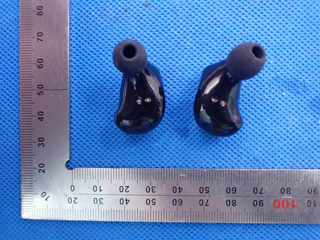
External Photos WHOLE VIEW OF EUT TOP VIEW OF EUT BOTTOM VIEW OF EUT FRONT VIEW OF EUT BACK VIEW OF EUT LEFT VIEW OF EUT RIGHT VIEW OF EUT Charging Dock TOP VIEW OF EUT BOTTOM VIEW OF EUT FRONT VIEW OF EUT BACK VIEW OF EUT LEFT VIEW OF EUT RIGHT VIEW OF EUT VIEW OF EUT(port)-1 VIEW OF EUT(port)-2

ID Label/Location Info

TRUE WIRELESS IN EAR MONITORS Fender TOUR FCC ID: 2AXKN-TOUR Foneric Electronics Co., Ltd. This device complies with Part 15 of the FCC Rules. Operation is subject to the following two conditions: (1) this device may not cause harmful interference, and (2) this device must accept any interference received, including interference that may cause undesired operation. package 50mm*50mm 210-147773

Internal Photos

Internal Photos Left OPEN VIEW OF EUT VIEW OF BATTERY INTERNAL VIEW OF EUT-1 INTERNAL VIEW OF EUT-2 BT Antenna INTERNAL VIEW OF EUT-3 INTERNAL VIEW OF EUT-4 Right OPEN VIEW OF EUT VIEW OF BATTERY INTERNAL VIEW OF EUT-1 INTERNAL VIEW OF EUT-2 BT Antenna INTERNAL VIEW OF EUT-3 INTERNAL VIEW OF EUT-4 Charging Dock OPEN VIEW OF EUT VIEW OF BATTERY INTERNAL VIEW OF EUT-1 INTERNAL VIEW OF EUT-2

RF Exposure Info

RF EXPOSURE EVALUATION 1. PRODUCT INFORMATION Product Description TOUR TRUE WIRELESS IN EAR MONITORS Model Name TOUR FCC ID 2AXKN-TOUR 2. EVALUATION METHOD According to 447498 D01 General RF Exposure Guidance v05 The 1-g and 10-g SAR test exclusion thresholds for 100 MHz to 6 GHz at test separation distances ≤ 50 mm are determined by: [(max. power of channel, including tune-up tolerance, mW)/(min. test separation distance, mm)] ·[√f(GHz)] ≤ 3.0 for 1-g SAR and ≤ 7.5 for 10-g extremity SAR. Where f(GHz) is the RF channel transmit frequency in GHz Power and distance are rounded to the nearest mW and mm before calculation 3. CALCULATION BR/EDR: P t = 1.603dBm=1.45mW The value of the Maximum output power P t is referred to the test report of the CFR47 §15.247. The result for RF exposure evaluation SAR=(1.45mW /5mm) .[√2.441GHz)]=0.45<3.0 for 1-g SAR and ≤ 7.5 for 10-g extremity SAR. BLE: GFSK 1Mbps: P t = 7.448dBm=5.56mW The value of the Maximum output power P t is referred to the test report of the CFR47 §15.247. The result for RF exposure evaluation SAR=(5.56mW /5mm) .[√2.480GHz)]= 1.75<3.0 for 1-g SAR and ≤ 7.5 for 10-g extremity SAR. GFSK 2Mbps: P t = 7.360dBm=5.45mW The value of the Maximum output power P t is referred to the test report of the CFR47 §15.247. The result for RF exposure evaluation SAR=(5.45mW /5mm) .[√2.480GHz)]= 1.71<3.0 for 1-g SAR and ≤ 7.5 for 10-g extremity SAR. 4. CONCLUSION The SAR evaluation is not required.

Test Report

Page 1 of 58 FCC Test Report Report No.: AGC10828200801FE02 FCC ID : 2AXKN-TOUR APPLICATION PURPOSE : Original Equipment PRODUCT DESIGNATION : TOUR TRUE WIRELESS IN EAR MONITORS BRAND NAME : Fender MODEL NAME : TOUR APPLICANT : Generation-S Private Limited DATE OF ISSUE : Sep. 22,2020 STANDARD(S) : FCC Part 15.247 REPORT VERSION : V1.0 Attestation of Global Compliance (Shenzhen) Co., Ltd Report No.: AGC10828200801FE02 Page 2 of 58 REPORT REVISE RECORD Report Version Revise Time Issued Date Valid Version Notes V1.0 / Sep. 22,2020 Valid Initial Release Report No.: AGC10828200801FE02 Page 3 of 58 TABLE OF CONTENTS 1. VERIFICATION OF COMPLIANCE .................................................................................................................. 4 2. GENERAL INFORMATION .............................................................................................................................. 5 2.1. PRODUCT DESCRIPTION ........................................................................................................................ 5 2.2. TABLE OF CARRIER FREQUENCYS ....................................................................................................... 5 2.3. RELATED SUBMITTAL(S)/GRANT(S) ....................................................................................................... 6 2.4. TEST METHODOLOGY ............................................................................................................................. 6 2.5. SPECIAL ACCESSORIES .......................................................................................................................... 6 2.6. EQUIPMENT MODIFICATIONS ................................................................................................................. 6 2.7. ANTENNA REQUIREMENT ....................................................................................................................... 6 3. MEASUREMENT UNCERTAINTY ................................................................................................................... 7 4. DESCRIPTION OF TEST MODES ................................................................................................................... 8 5. SYSTEM TEST CONFIGURATION .................................................................................................................. 9 5.1. CONFIGURATION OF TESTED SYSTEM ................................................................................................. 9 5.2. EQUIPMENT USED IN TESTED SYSTEM ................................................................................................ 9 5.3. SUMMARY OF TEST RESULTS ................................................................................................................ 9 6. TEST FACILITY .............................................................................................................................................. 10 7. PEAK OUTPUT POWER ................................................................................................................................ 11 7.1. MEASUREMENT PROCEDURE .............................................................................................................. 11 7.2. TEST SET-UP (BLOCK DIAGRAM OF CONFIGURATION) .................................................................... 11 7.3. LIMITS AND MEASUREMENT RESULT .................................................................................................. 12 8. 6 DB BANDWIDTH ......................................................................................................................................... 16 8.1. MEASUREMENT PROCEDURE .............................................................................................................. 16 8.2. TEST SET-UP (BLOCK DIAGRAM OF CONFIGURATION) .................................................................... 16 8.3. LIMITS AND MEASUREMENT RESULTS ............................................................................................... 16 9. CONDUCTED SPURIOUS EMISSION........................................................................................................... 18 9.1. MEASUREMENT PROCEDURE .............................................................................................................. 18 9.2. TEST SET-UP (BLOCK DIAGRAM OF CONFIGURATION) .................................................................... 18 9.3. MEASUREMENT EQUIPMENT USED .................................................................................................... 18 9.4. LIMITS AND MEASUREMENT RESULT .................................................................................................. 18 10. MAXIMUM CONDUCTED OUTPUT POWER SPECTRAL DENSITY ........................................................ 26 10.1. MEASUREMENT PROCEDURE ............................................................................................................ 26 10.2. TEST SET-UP (BLOCK DIAGRAM OF CONFIGURATION) .................................................................. 26 10.3. MEASUREMENT EQUIPMENT USED .................................................................................................. 26 10.4. LIMITS AND MEASUREMENT RESULT................................................................................................ 26 11. RADIATED EMISSION ................................................................................................................................. 28 11.1. MEASUREMENT PROCEDURE ............................................................................................................ 28 11.2. TEST SETUP .......................................................................................................................................... 29 11.3. LIMITS AND MEASUREMENT RESULT................................................................................................ 30 11.4. TEST RESULT ........…

Text truncated - open the document above for the full version.

Test Report

Report No.: AGC10828200801FE02 Page 45 of 58 RIGHT VIEW OF EUT Left OPEN VIEW OF EUT Report No.: AGC10828200801FE02 Page 46 of 58 VIEW OF BATTERY INTERNAL VIEW OF EUT-1 BT Antenna Report No.: AGC10828200801FE02 Page 47 of 58 INTERNAL VIEW OF EUT-2 INTERNAL VIEW OF EUT-3 Report No.: AGC10828200801FE02 Page 48 of 58 INTERNAL VIEW OF EUT-4 Right OPEN VIEW OF EUT Report No.: AGC10828200801FE02 Page 49 of 58 VIEW OF BATTERY INTERNAL VIEW OF EUT-1 BT Antenna Report No.: AGC10828200801FE02 Page 50 of 58 INTERNAL VIEW OF EUT-2 INTERNAL VIEW OF EUT-3 Report No.: AGC10828200801FE02 Page 51 of 58 INTERNAL VIEW OF EUT-4 Charging Dock TOP VIEW OF EUT Report No.: AGC10828200801FE02 Page 52 of 58 BOTTOM VIEW OF EUT FRONT VIEW OF EUT Report No.: AGC10828200801FE02 Page 53 of 58 BACK VIEW OF EUT LEFT VIEW OF EUT Report No.: AGC10828200801FE02 Page 54 of 58 RIGHT VIEW OF EUT VIEW OF EUT(port)-1 Report No.: AGC10828200801FE02 Page 55 of 58 VIEW OF EUT(port)-2 OPEN VIEW OF EUT Report No.: AGC10828200801FE02 Page 56 of 58 VIEW OF BATTERY INTERNAL VIEW OF EUT-1 Report No.: AGC10828200801FE02 Page 57 of 58 INTERNAL VIEW OF EUT-2 ----THE END ---- Conditions of Issuance of Test Reports 1. All samples and goods are accepted by the Attestation of Global Compliance (Shenzhen) Co., Ltd (the “Company”) solely for testing and reporting in accordance with the following terms and conditions. The company provides its services on the basis that such terms and conditions constitute express agreement between the company and any person, firm or company requesting its services (the “Clients”). 2. Any report issued by Company as a result of this application for testing services (the “Report”) shall be issued in confidence to the Clients and the Report will be strictly treated as such by the Company. It may not be reproduced either in its entirety or in part and it may not be used for advertising or other unauthorized purposes without the written consent of the Company. The Clients to whom the Report is issued may, however, show or send it, or a certified copy thereof prepared by the Company to its customer, supplier or other persons directly concerned. The Company will not, without the consent of the Clients, enter into any discussion or correspondence with any third party concerning the contents of the Report, unless required by the relevant governmental authorities, laws or court orders. 3.The Company shall not be called or be liable to be called to give evidence or testimony on the Report in a court of law without its prior written consent, unless required by the relevant governmental authorities, laws or court orders. 4. The non-CMA report issued by AGC is only permitted to be used by the client as internal reference use and shall not be used for public demonstration purpose. 5. In the event of the improper use of the report as determined by the Company, the Company reserves the right to withdraw it, and to adopt any other additional remedies which may be appropriate. 6. Samples submitted for testing are accepted on the understanding that the Report issued cannot form the basis of, or be the instrument for, any legal action against the Company. 7. The Company will not be liable for or accept responsibility for any loss or damage however arising from the use of information contained in any of its Reports or in any communication whatsoever about its said tests or investigations. 8.Clients wishing to use the Report in court proceedings or arbitration shall inform the Company to that effect prior to submitting the sample for testing. 9. The Company is not responsible for recalling the electronic version of the original report when any revision is made to them. The Client assumes the responsibility to providing the revised version to any interested party who uses them. 10. Subject to the variable length of retention time for test data and report stored hereinto as otherwise specifically required by individual accreditation authorities, the Company will only keep the supporting test data and information of the test report for a period of six years. The data and information will be disposed of after the aforementioned retention period has elapsed. Under no circumstances shall we provide any data and information which has been disposed of after retention period. Under no circumstances shall we be liable for damage of any kind, including (but not limited to) compensatory damages, lost profits, lost data, or any form of special, incidental, indirect, consequential or punitive damages of any kind, whether based on breach of contract of warranty, tort (including negligence), product liability or otherwise, even if we are informed in advance of the possibility of such damages.

Test Report

Page 1 of 58 FCC Test Report Report No.: AGC10828200801FE04 FCC ID : 2AXKN-TOUR APPLICATION PURPOSE : Original Equipment PRODUCT DESIGNATION : TOUR TRUE WIRELESS IN EAR MONITORS BRAND NAME : Fender MODEL NAME : TOUR APPLICANT : Generation-S Private Limited DATE OF ISSUE : Sep. 22,2020 STANDARD(S) : FCC Part 15.247 REPORT VERSION : V1.0 Attestation of Global Compliance (Shenzhen) Co., Ltd Report No.: AGC10828200801FE04 Page 2 of 58 REPORT REVISE RECORD Report Version Revise Time Issued Date Valid Version Notes V1.0 / Sep. 22,2020 Valid Initial Release Report No.: AGC10828200801FE04 Page 3 of 58 TABLE OF CONTENTS 1. VERIFICATION OF COMPLIANCE .................................................................................................................. 4 2. GENERAL INFORMATION .............................................................................................................................. 5 2.1. PRODUCT DESCRIPTION ........................................................................................................................ 5 2.2. TABLE OF CARRIER FREQUENCYS ....................................................................................................... 5 2.3. RELATED SUBMITTAL(S)/GRANT(S) ....................................................................................................... 6 2.4. TEST METHODOLOGY ............................................................................................................................. 6 2.5. SPECIAL ACCESSORIES .......................................................................................................................... 6 2.6. EQUIPMENT MODIFICATIONS ................................................................................................................. 6 2.7. ANTENNA REQUIREMENT ....................................................................................................................... 6 3. MEASUREMENT UNCERTAINTY ................................................................................................................... 7 4. DESCRIPTION OF TEST MODES ................................................................................................................... 8 5. SYSTEM TEST CONFIGURATION .................................................................................................................. 9 5.1. CONFIGURATION OF TESTED SYSTEM ................................................................................................. 9 5.2. EQUIPMENT USED IN TESTED SYSTEM ................................................................................................ 9 5.3. SUMMARY OF TEST RESULTS ................................................................................................................ 9 6. TEST FACILITY .............................................................................................................................................. 10 7. PEAK OUTPUT POWER ................................................................................................................................ 11 7.1. MEASUREMENT PROCEDURE .............................................................................................................. 11 7.2. TEST SET-UP (BLOCK DIAGRAM OF CONFIGURATION) .................................................................... 11 7.3. LIMITS AND MEASUREMENT RESULT .................................................................................................. 12 8. 6 DB BANDWIDTH ......................................................................................................................................... 16 8.1. MEASUREMENT PROCEDURE .............................................................................................................. 16 8.2. TEST SET-UP (BLOCK DIAGRAM OF CONFIGURATION) .................................................................... 16 8.3. LIMITS AND MEASUREMENT RESULTS ............................................................................................... 16 9. CONDUCTED SPURIOUS EMISSION........................................................................................................... 18 9.1. MEASUREMENT PROCEDURE .............................................................................................................. 18 9.2. TEST SET-UP (BLOCK DIAGRAM OF CONFIGURATION) .................................................................... 18 9.3. MEASUREMENT EQUIPMENT USED .................................................................................................... 18 9.4. LIMITS AND MEASUREMENT RESULT .................................................................................................. 18 10. MAXIMUM CONDUCTED OUTPUT POWER SPECTRAL DENSITY ........................................................ 26 10.1. MEASUREMENT PROCEDURE ............................................................................................................ 26 10.2. TEST SET-UP (BLOCK DIAGRAM OF CONFIGURATION) .................................................................. 26 10.3. MEASUREMENT EQUIPMENT USED .................................................................................................. 26 10.4. LIMITS AND MEASUREMENT RESULT................................................................................................ 26 11. RADIATED EMISSION ................................................................................................................................. 28 11.1. MEASUREMENT PROCEDURE ............................................................................................................ 28 11.2. TEST SETUP .......................................................................................................................................... 29 11.3. LIMITS AND MEASUREMENT RESULT................................................................................................ 30 11.4. TEST RESULT ........…

Text truncated - open the document above for the full version.

Test Report

Report No.: AGC10828200801FE04 Page 45 of 58 RIGHT VIEW OF EUT Left OPEN VIEW OF EUT Report No.: AGC10828200801FE04 Page 46 of 58 VIEW OF BATTERY INTERNAL VIEW OF EUT-1 BT Antenna Report No.: AGC10828200801FE04 Page 47 of 58 INTERNAL VIEW OF EUT-2 INTERNAL VIEW OF EUT-3 Report No.: AGC10828200801FE04 Page 48 of 58 INTERNAL VIEW OF EUT-4 Right OPEN VIEW OF EUT Report No.: AGC10828200801FE04 Page 49 of 58 VIEW OF BATTERY INTERNAL VIEW OF EUT-1 BT Antenna Report No.: AGC10828200801FE04 Page 50 of 58 INTERNAL VIEW OF EUT-2 INTERNAL VIEW OF EUT-3 Report No.: AGC10828200801FE04 Page 51 of 58 INTERNAL VIEW OF EUT-4 Charging Dock TOP VIEW OF EUT Report No.: AGC10828200801FE04 Page 52 of 58 BOTTOM VIEW OF EUT FRONT VIEW OF EUT Report No.: AGC10828200801FE04 Page 53 of 58 BACK VIEW OF EUT LEFT VIEW OF EUT Report No.: AGC10828200801FE04 Page 54 of 58 RIGHT VIEW OF EUT VIEW OF EUT(port)-1 Report No.: AGC10828200801FE04 Page 55 of 58 VIEW OF EUT(port)-2 OPEN VIEW OF EUT Report No.: AGC10828200801FE04 Page 56 of 58 VIEW OF BATTERY INTERNAL VIEW OF EUT-1 Report No.: AGC10828200801FE04 Page 57 of 58 INTERNAL VIEW OF EUT-2 ----THE END ---- Conditions of Issuance of Test Reports 1. All samples and goods are accepted by the Attestation of Global Compliance (Shenzhen) Co., Ltd (the “Company”) solely for testing and reporting in accordance with the following terms and conditions. The company provides its services on the basis that such terms and conditions constitute express agreement between the company and any person, firm or company requesting its services (the “Clients”). 2. Any report issued by Company as a result of this application for testing services (the “Report”) shall be issued in confidence to the Clients and the Report will be strictly treated as such by the Company. It may not be reproduced either in its entirety or in part and it may not be used for advertising or other unauthorized purposes without the written consent of the Company. The Clients to whom the Report is issued may, however, show or send it, or a certified copy thereof prepared by the Company to its customer, supplier or other persons directly concerned. The Company will not, without the consent of the Clients, enter into any discussion or correspondence with any third party concerning the contents of the Report, unless required by the relevant governmental authorities, laws or court orders. 3.The Company shall not be called or be liable to be called to give evidence or testimony on the Report in a court of law without its prior written consent, unless required by the relevant governmental authorities, laws or court orders. 4. The non-CMA report issued by AGC is only permitted to be used by the client as internal reference use and shall not be used for public demonstration purpose. 5. In the event of the improper use of the report as determined by the Company, the Company reserves the right to withdraw it, and to adopt any other additional remedies which may be appropriate. 6. Samples submitted for testing are accepted on the understanding that the Report issued cannot form the basis of, or be the instrument for, any legal action against the Company. 7. The Company will not be liable for or accept responsibility for any loss or damage however arising from the use of information contained in any of its Reports or in any communication whatsoever about its said tests or investigations. 8.Clients wishing to use the Report in court proceedings or arbitration shall inform the Company to that effect prior to submitting the sample for testing. 9. The Company is not responsible for recalling the electronic version of the original report when any revision is made to them. The Client assumes the responsibility to providing the revised version to any interested party who uses them. 10. Subject to the var…

Text truncated - open the document above for the full version.

Contact Information

Applicant

Johnson Goh
[email protected]+65-98359189Fax: N/A

Technical Contact

Generation-S Private Limited
[email protected]

Singapore

Test Firm

Attestation of Global Compliance (Shenzhen) Co., LDoris Li
[email protected]+86-755-25234088

Technical Specifications

#Rule PartsFrequency RangePower Output
215C2.40 GHz - 2.48 GHz5.40 mW
Confidentiality
Long Term
Grant Notes
Power listed is the maximum conducted output power .

Other Applications from Generation-S Private Limited

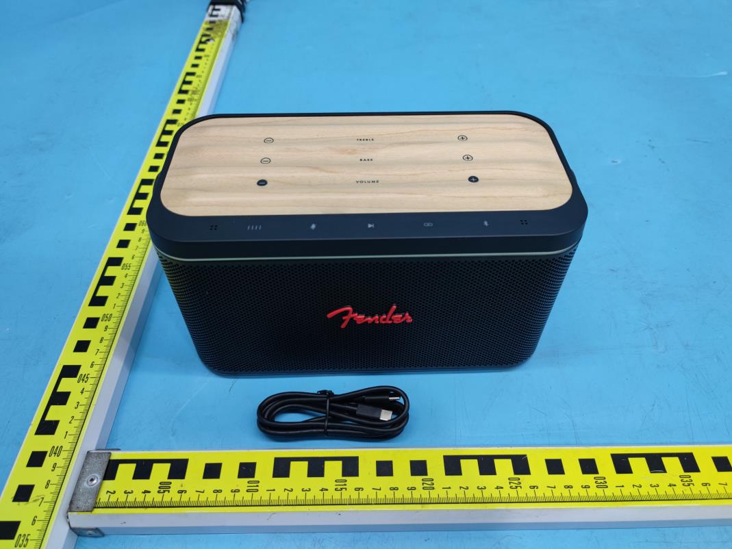
Fender RIFF Bluetooth Speaker - FCC ID 2AXKN-RIFF - Generation-S Private Limited
2AXKN-RIFF

Fender RIFF Bluetooth Speaker

Dec 07, 2022

Equipment Class

DTS - Digital Transmission System