2AXLP-CONNECTCHECKConnectCheck
International Game Technology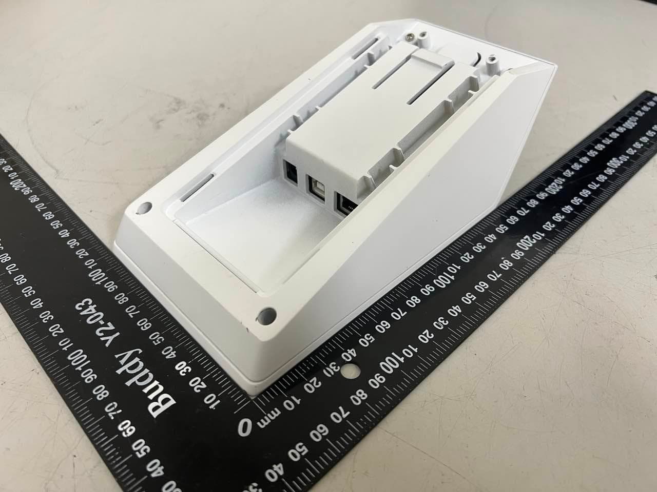
Click to zoom
Application Details
- Equipment Class
- NII - Unlicensed National Information Infrastructure TX
- Date of Grant
- Oct 04, 2023
- Application Purpose
- Original Equipment
- Date of Application
- Oct 04, 2023
- Equipment Note
- ConnectCheck
- Frequency Range
- 5745.00000000 - 5825.00000000
- Country
- United States
Documents & Files
Document Text
Text extracted from the exhibit documents filed with the FCC. Open a document above to read the original.
Users Manual
ConnectCheck™ Service Manual 90-230386-00 Baseline ConnectCheck™ September 2023 Technology Training and Support Services 10 Memorial Boulevard, Providence, RI 02903 USA ConnectCheck™ - Service Manual Warranty Information in this document is subject to change without notice and does not represent a commitment on the part of IGT, a wholly owned subsidiary of IGT. No part of this manual may be reproduced or transmitted in any form or by any means, electronic or mechanical, including photocopying and recording, for any purpose other than the purchaser's personal use without written permission of IGT. Nothing contained in this document shall be construed as a warranty. The warranty, if any, for a product shall be contained in the contract with IGT for the purchase, lease or license of the product. ALL OTHER WARRANTIES, EXPRESS OR IMPLIED, INCLUDING BUT NOT LIMITED TO WARRANTIES OF MERCHANTABILITY, FITNESS FOR A PARTICULAR PURPOSE OR NON-INFRINGEMENT, ARE HEREBY DISCLAIMED. IN NO EVENT SHALL IGT BE LIABLE FOR DIRECT, INDIRECT, INCIDENTAL, PUNITIVE OR CONSEQUENTIAL DAMAGES, INCLUDING BUT NOT LIMITED TO LOSS OF USE, REVENUE OR PROFITS. Hardware Warning! The following servicing instructions and/or information is for use by QUALIFIED PERSONNEL ONLY. Third-Party Trademarks All other trademarks and registered trademarks are the property of their respective owners, without intent to infringe. Hardware Trademark and Copyright Information © 2023 IGT. All rights reserved. Certain trademarks and/or service marks used herein are the property of their respective third party owners. The use of such marks herein is for identification purposes only, and does not imply an endorsement by IGT of the mark owner, or vice-versa, or that such mark owner has authorized IGT to promote its products and/or services. Contact Information IGT 10 Memorial Boulevard Providence, Rhode Island 02903 1-401-392-1000 IGT Support 1-866-777-8448 We Appreciate Your Ideas! Help the IGT team hit the jackpot. Please send your feedback to [email protected] Give it to us straight – We appreciate your input. 2ConnectCheck™ Table of Contents Chapter 1 Introduction5 Overview5 Controller Board6 3.5" LCD/Capacitive Touchscreen6 Audio Indicator6 2D Barcode Scanner6 Environmental Specification7 Electrical Specification8 Communications Specification8 Mechanical Specification8 External Ports9 Chapter 2 Installation11 Counter-Mount Installation11 Chapter 3 Diagnostics15 Required Equipment for the USB Method15 Diagnostics Tests15 Device Information17 Peripheral Test17 Configuration18 Firmware update from USB19 *** Reboot ***20 Chapter 4 Download21 Downloading ConnectCheck Firmware Using Terminal Diagnostics21 Downloading ConnectCheck Firmware Using Standalone Diagnostics21 Chapter 5 Configuration23 Wired Configuration24 Chapter 6 Operation25 Chapter 7 Hardware27 Required Tools28 Removing the Main Controller Board28 Removing the Barcode Scanner Engine30 Removing the LCD Assembly31 Chapter 8 Troubleshooting33 Troubleshooting Techniques—The Seven-Step Troubleshooting Method33 Step One: Identify the Problem33 Step Two: Determine Related Symptoms34 Step Three: Analyze the Symptoms34 Step Four: Isolate the Problem35 Step Five: Correct the Problem36 Step Six: Verify the Correction36 Step Seven: Document the Process36 Troubleshooting Worksheet37 General Troubleshooting39 Chapter 9 Preventive Maintenance43 ConnectCheck™3 Cleaning Materials43 External Cleaning43 When You Are Finished43 Chapter 10 Handling Precautions45 What is ESD?45 Becoming “Static Safe”45 ESD-Induced Failure Modes46 Radiated Electromagnetic Fields46 Conducted Charges46 Typical Symptoms of ESD Damage46 Common False Assumptions Concerning ESD46 ESD Precautions Checklist47 Recommended Devices47 Precautionary Practices47 Recommended Handling - Example48 Proper Grounding Technique48 IGT Manufacturing Specification49 Packaging49 General Packaging Procedures49 Chapter 11 Diagrams51 Chapter 12 Spare Parts and Tools53 Chapter 13 Product Safety & Approvals55 Safety Instructions55 Model Rating Label56 FCC56 FCC Radiation Exposure Statement56 Industry Canada57 European Union57 4ConnectCheck™ Chapter 1 Introduction Overview The ConnectCheck is a multipurpose terminal peripheral that functions as a customer ticket checker for physical and digital tickets, as well as a digital play device, also known as Connected Play. As a customer ticket checker, players may check their printed ticket for a winning status by placing the ticket in view of the barcode scanner to scan the barcode. As a Connected Play device, it facilitates paperless interactions and players can use a lottery app to create and use digital playslips and make cashless payments with their lottery eWallet. The ConnectCheckconsists of an integrated barcode scanner and LCD touchscreen player display. It is installed in proximity to the retailer terminal and communicates through a wired connection to the terminal to the host system. Status messages are communicated from the host through the retailer terminal and to the ConnectCheck to be displayed to the player. Up to three (3) devices can be connected to each retailer counter-top terminal. Figure 1-1 ConnectCheck with Optional Counter Mount ConnectCheck™5 Chapter1 Introduction The ConnectCheck includes the following components: l 2D Barcode Scanner (Zebra SE4107) l 3.5" LCD Capacitive Touchscreen Display l Controller Board l Audio Indicator l Wired Communications Controller Board The 51-XXXX-01E is the controller board for the ConnectCheck. The main chip is a Cortex-A7 @900 MHz RAM1Gb DDR3L. 3.5" LCD/Capacitive Touchscreen The ConnectCheck utilizes a 5" backlit LCD/capacitive touchscreen. The display brightness is adjusted automatically depending on the environment. Audio Indicator The audio output in this device is generated by an audio transducer with a rated frequency of 2,000 Hz. The sound produced is a series of beeps and clicks which are controlled through software. The sound output is as fo…
Text truncated - open the document above for the full version.
Cover Letter(s)
International Game Technology Equipment Autorisation Division Federal Communications Commission 7435 Oakland Mills Road Columbia, MD 21046 FCC ID: 2AXLP-CONNECTCHECK Request for Short-Term Confidentiality Pursuant to Sections 0.457 and 0.459 of the commission rules, and in accordance with the FCC Public notice dated June 15, 2004 (DA 04-1705), we hereby request short-term confidentiality for the following items prior to marketing the device.: ⚫ Test Setup Photos ⚫ External Photos ⚫ Internal Photos ⚫ User Manual These documents contain detailed system and equipment description and related information about the product which International Game Technology considers to be proprietary, confidential, and a custom design and, otherwise would not release to the general public. Since this design is a basis from which future technological products will evolve, International Game Technologyconsiders this information to be of benefit to its competitors, and that the disclosure of information in these documents would give competitors an unfair advantage in the market. This request is being made retroactively due to an over site on our part. We understand that the information has been publicly available 180 days after date of grant. Signature: Date: 2023-10-04 City: Taipei City Name: Kent Liu (Authorized Agent) Function: Manager Telephone: +886-2-2641-8198 EXT.620 E-mail: [email protected]
External Photos
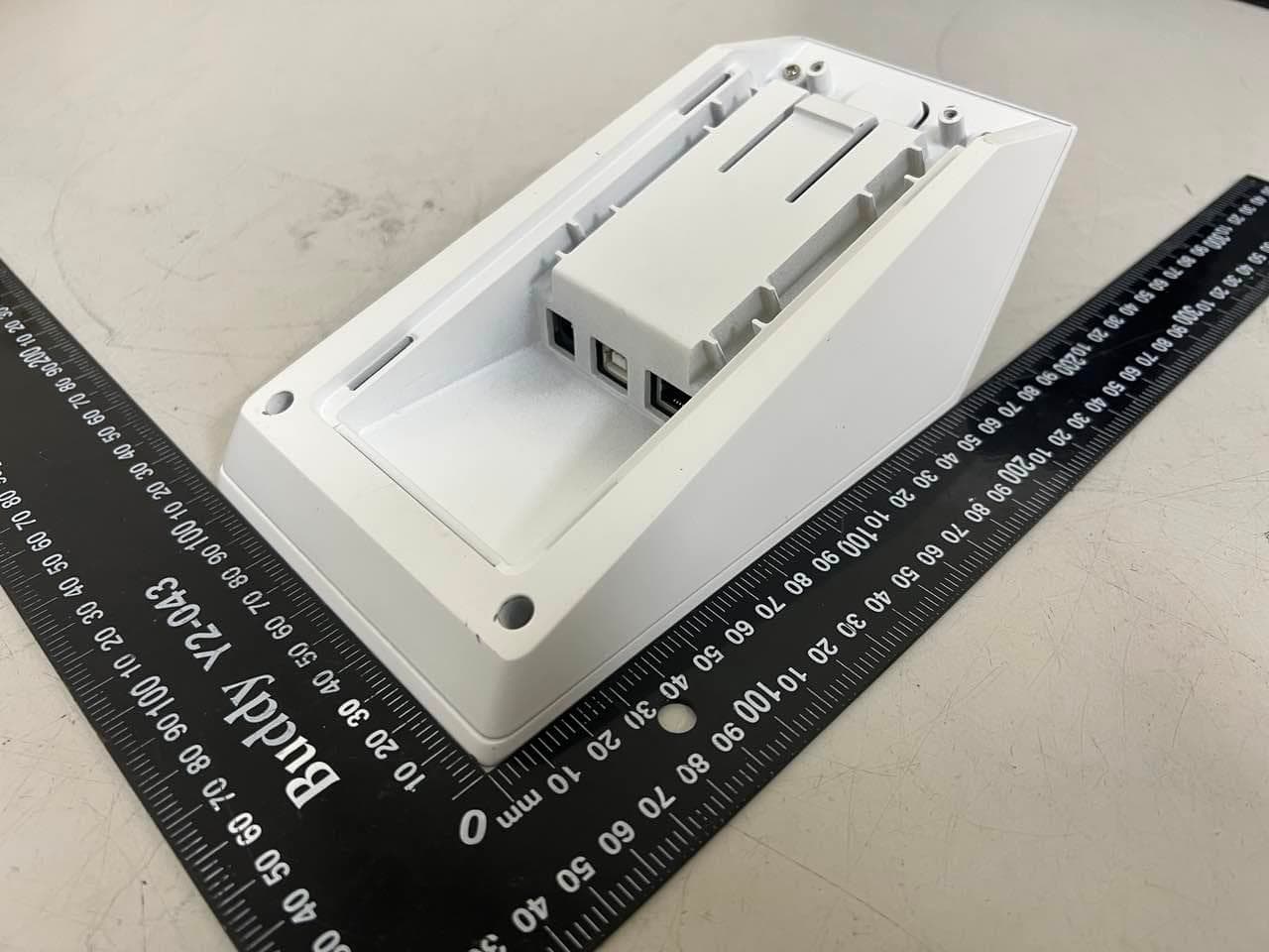
Appendix No.: EP-2308T050-2 APPENDIX-EUT PHOTOS Project No.: 2308T050 Page 1 of 19 Appendix No.: EP-2308T050-2 APPENDIX-EUT PHOTOS Project No.: 2308T050 Page 2 of 19 Appendix No.: EP-2308T050-2 APPENDIX-EUT PHOTOS Project No.: 2308T050 Page 3 of 19 Appendix No.: EP-2308T050-2 APPENDIX-EUT PHOTOS Project No.: 2308T050 Page 4 of 19 Appendix No.: EP-2308T050-2 APPENDIX-EUT PHOTOS Project No.: 2308T050 Page 5 of 19 Appendix No.: EP-2308T050-2 APPENDIX-EUT PHOTOS Project No.: 2308T050 Page 6 of 19 Appendix No.: EP-2308T050-2 APPENDIX-EUT PHOTOS Project No.: 2308T050 Page 7 of 19 Appendix No.: EP-2308T050-2 APPENDIX-EUT PHOTOS Project No.: 2308T050 Page 8 of 19 Appendix No.: EP-2308T050-2 APPENDIX-EUT PHOTOS Project No.: 2308T050 Page 9 of 19
ID Label/Location Info
Label Location :
Internal Photos
Appendix No.: EP-2308T050-2 APPENDIX-EUT PHOTOS Project No.: 2308T050 Page 10 of 19 NFC Antenna Appendix No.: EP-2308T050-2 APPENDIX-EUT PHOTOS Project No.: 2308T050 Page 11 of 19 Appendix No.: EP-2308T050-2 APPENDIX-EUT PHOTOS Project No.: 2308T050 Page 12 of 19 Appendix No.: EP-2308T050-2 APPENDIX-EUT PHOTOS Project No.: 2308T050 Page 13 of 19 Appendix No.: EP-2308T050-2 APPENDIX-EUT PHOTOS Project No.: 2308T050 Page 14 of 19 Appendix No.: EP-2308T050-2 APPENDIX-EUT PHOTOS Project No.: 2308T050 Page 15 of 19 Wi-Fi/BT Antenna Appendix No.: EP-2308T050-2 APPENDIX-EUT PHOTOS Project No.: 2308T050 Page 16 of 19 Appendix No.: EP-2308T050-2 APPENDIX-EUT PHOTOS Project No.: 2308T050 Page 17 of 19 Appendix No.: EP-2308T050-2 APPENDIX-EUT PHOTOS Project No.: 2308T050 Page 18 of 19 RF IC: RTL8821CU1 Appendix No.: EP-2308T050-2 APPENDIX-EUT PHOTOS Project No.: 2308T050 Page 19 of 19 RF IC: PN5190
RF Exposure Info
Report No.: BTL-FCCP-5-2308T050 Project No.: 2308T050 Page 1 of 9 Report Version: R00 FCC RF Exposure Report FCC ID: 2AXLP-CONNECTCHECK Report No. : BTL-FCCP-5-2308T050 Equipment : ConnectCheck™ Model Name : ConnectCheck™ Brand Name : IGT Applicant : International Game Technology Address : 9295 Prototype Drive, Reno, NV Standard(s) : 47 CFR § 2.1091 FCC Guidelines for Human Exposure IEEE C95.1 Date of Receipt : 2022/11/17 Date of Test : 2022/11/29 ~ 2023/6/28 Issued Date : 2023/9/6 The above equipment has been tested and found in compliance with the requirement of the above standards by BTL Inc. Prepared by : Eddie Lee, Engineer Approved by : Jerry Chuang, Supervisor BTL Inc. No.18, Ln. 171, Sec. 2, Jiuzong Rd., Neihu Dist., Taipei City 114, Taiwan Tel: +886-2-2657-3299 Fax: +886-2-2657-3331 Web: www.newbtl.com Service mail: [email protected] Report No.: BTL-FCCP-5-2308T050 Project No.: 2308T050 Page 2 of 9 Report Version: R00 Declaration BTL represents to the client that testing is done in accordance with standard procedures as applicable and that test instruments used has been calibrated with standards traceable to international standard(s) and/or national standard(s). BTL's reports apply only to the specific samples tested under conditions. It is manufacture’s responsibility to ensure that additional production units of this model are manufactured with the identical electrical and mechanical components. BTL shall have no liability for any declarations, inferences or generalizations drawn by the client or others from BTL issued reports. This report is the confidential property of the client. As a mutual protection to the clients, the public and ourselves, the test report shall not be reproduced, except in full, without our written approval. BTL’s laboratory quality assurance procedures are in compliance with the ISO/IEC 17025 requirements, and accredited by the conformity assessment authorities listed in this test report. BTL is not responsible for the sampling stage, so the results only apply to the sample as received. The information, data and test plan are provided by manufacturer which may affect the validity of results, so it is manufacturer’s responsibility to ensure that the apparatus meets the essential requirements of applied standards and in all the possible configurations as representative of its intended use. Limitation For the use of the authority's logo is limited unless the Test Standard(s)/Scope(s)/Item(s) mentioned in this test report is (are) included in the conformity assessment authorities acceptance respective. Please note that the measurement uncertainty is provided for informational purpose only and are not use in determining the Pass/Fail results. Report No.: BTL-FCCP-5-2308T050 Project No.: 2308T050 Page 3 of 9 Report Version: R00 REVISION HISTORY Report No. Version Description Issued Date Note BTL-FCCP-5-2308T050 R00 Original Report. 2023/9/6 Valid Report No.: BTL-FCCP-5-2308T050 Project No.: 2308T050 Page 4 of 9 Report Version: R00 1. LIMITS According to § 1.1310 Radiofrequency radiation exposure limits. (a) Specific absorption rate (SAR) shall be used to evaluate the environmental impact of human exposure to radiofrequency (RF) radiation as specified in § 1.1307(b) of this part within the frequency range of 100 kHz to 6 GHz (inclusive). (b) The SAR limits for occupational/controlled exposure are 0.4 W/kg, as averaged over the whole body, and a peak spatial-average SAR of 8 W/kg, averaged over any 1 gram of tissue (defined as a tissue volume in the shape of a cube). Exceptions are the parts of the human body treated as extremities, such as hands, wrists, feet, ankles, and pinnae, where the peak spatial-average SAR limit for occupational/controlled exposure is 20 W/kg, averaged over any 10 grams of tissue (defined as a tissue volume in the shape of a cube). Exposure may be averaged over a time period not to exceed 6 minutes to determine compliance with occupational/controlled SAR limits. (c) The SAR limits for general population/uncontrolled exposure are 0.08 W/kg, as averaged over the whole body, and a peak spatial-average SAR of 1.6 W/kg, averaged over any 1 gram of tissue (defined as a tissue volume in the shape of a cube). Exceptions are the parts of the human body treated as extremities, such as hands, wrists, feet, ankles, and pinnae, where the peak spatial-average SAR limit is 4 W/kg, averaged over any 10 grams of tissue (defined as a tissue volume in the shape of a cube). Exposure may be averaged over a time period not to exceed 30 minutes to determine compliance with general population/uncontrolled SAR limits. (e) Limits for Maximum Permissible Exposure (MPE) to radiofrequency electromagnetic fields (Table 1). Frequency range (MHz) Electric field strength (V/m) Magnetic field strength (A/m) Power density (mW/cm 2 ) Averaging time (minutes) (i) Limits for Occupational/Controlled Exposure 0.3-3.0 614 1.63 *(100) ≤6 3.0-30 1842/f 4.89/f *(900/f 2 ) <6 30-300 61.4 0.163 1.0 <6 300-1.500 f/300 <6 1.500-100.000 5 <6 (ii) Limits for General Population/Uncontrolled Exposure 0.3-1.34 614 1.63 *(100) <30 1.34-30 824/f 2.19/f *(180/f 2 ) <30 30-300 27.5 0.073 0.2 <30 300-1.500 f/1500 <30 1.500-100.000 1.0 <30 f = frequency in MHz. * = Plane-wave equivalent power density. Report No.: BTL-FCCP-5-2308T050 Project No.: 2308T050 Page 5 of 9 Report Version: R00 2. APPLIED EXEMPTION CRITERIA Refer to KDB 447498 D04, ticked item is applied: For RF Exposure Test Exemptions for Single Source: ☒ 1-mW Test Exemption Per § 1.1307(b)(3)(i)(A), a single RF source is exempt RF device (from the requirement to show data demonstrating compliance to RF exposure limits, as previously mentioned) if the available maximum time-averaged power is no more than 1 mW, regardless of separation distance. This exemption applies to all operating configurations and exposure conditions, for the frequency range 100 kHz to 100 GHz, regardless of fixed, mobile, or portable device exposure conditions…
Text truncated - open the document above for the full version.
Test Report
碧擎科技有限公司 Bi Qing Technology Co., Ltd. 碧擎科技有限公司 Bi Qing Technology Co., Ltd. Z X Y 碧擎科技有限公司 Bi Qing Technology Co., Ltd. 碧擎科技有限公司 Bi Qing Technology Co., Ltd. Dual Band Test DataEfficiency (%)Peak Gain (dBi) 2400-1.8 66.2 4.5 2450-0.7 85.6 5.8 2500-1.3 74.0 5.2 5150-1.9 64.5 3.5 5250-1.4 72.2 4.5 5350-2.0 63.7 4.0 5470-1.8 66.7 3.7 5600-1.8 65.8 4.5 5725-1.6 68.9 5.0 5785-1.6 70.0 5.2 5850-1.2 76.1 5.6 -7.0 -6.0 -5.0 -4.0 -3.0 -2.0 -1.0 0.0 24002450250051505250535054705600572557855850 Dual Band Antenna 碧擎科技有限公司 Bi Qing Technology Co., Ltd. 碧擎科技有限公司 Bi Qing Technology Co., Ltd. 碧擎科技有限公司 Bi Qing Technology Co., Ltd. 碧擎科技有限公司 Bi Qing Technology Co., Ltd. 碧擎科技有限公司 Bi Qing Technology Co., Ltd. 碧擎科技有限公司 Bi Qing Technology Co., Ltd. 碧擎科技有限公司 Bi Qing Technology Co., Ltd. 碧擎科技有限公司 Bi Qing Technology Co., Ltd. 碧擎科技有限公司 Bi Qing Technology Co., Ltd. 碧擎科技有限公司 Bi Qing Technology Co., Ltd. 碧擎科技有限公司 Bi Qing Technology Co., Ltd. 碧擎科技有限公司 Bi Qing Technology Co., Ltd. Thank You!
Test Report
Report No.: BTL-FCCP-3-2308T050 Project No.: 2308T050 Page 1 of 24 Report Version: R00 FCC Radio Test Report FCC ID: 2AXLP-CONNECTCHECK Report No. : BTL-FCCP-3-2308T050 Equipment : ConnectCheck™ Model Name : ConnectCheck™ Brand Name : IGT Applicant : International Game Technology Address : 9295 Prototype Drive, Reno, NV Radio Function : RLAN 5 GHz (U-NII 2A, U-NII 2C) FCC Rule Part(s) : FCC CFR Title 47, Part 15, Subpart E (15.407) Date of Receipt : 2022/11/17 Date of Test : 2022/11/29 ~ 2023/1/11 Issued Date : 2023/9/6 The above equipment has been tested and found in compliance with the requirement of the above standards by BTL Inc. Prepared by : Eddie Lee, Engineer Approved by : Jerry Chuang, Supervisor BTL Inc. No.18, Ln. 171, Sec. 2, Jiuzong Rd., Neihu Dist., Taipei City 114, Taiwan Tel: +886-2-2657-3299 Fax: +886-2-2657-3331 Web: www.newbtl.com Service mail: [email protected] Report No.: BTL-FCCP-3-2308T050 Project No.: 2308T050 Page 2 of 24 Report Version: R00 Declaration BTL represents to the client that testing is done in accordance with standard procedures as applicable and that test instruments used has been calibrated with standards traceable to international standard(s) and/or national standard(s). BTL's reports apply only to the specific samples tested under conditions. It is manufacture’s responsibility to ensure that additional production units of this model are manufactured with the identical electrical and mechanical components. BTL shall have no liability for any declarations, inferences or generalizations drawn by the client or others from BTL issued reports. This report is the confidential property of the client. As a mutual protection to the clients, the public and ourselves, the test report shall not be reproduced, except in full, without our written approval. BTL’s laboratory quality assurance procedures are in compliance with the ISO/IEC 17025 requirements, and accredited by the conformity assessment authorities listed in this test report. BTL is not responsible for the sampling stage, so the results only apply to the sample as received. The information, data and test plan are provided by manufacturer which may affect the validity of results, so it is manufacturer’s responsibility to ensure that the apparatus meets the essential requirements of applied standards and in all the possible configurations as representative of its intended use. Limitation For the use of the authority's logo is limited unless the Test Standard(s)/Scope(s)/Item(s) mentioned in this test report is (are) included in the conformity assessment authorities acceptance respective. Please note that the measurement uncertainty is provided for informational purpose only and are not use in determining the Pass/Fail results. Report No.: BTL-FCCP-3-2308T050 Project No.: 2308T050 Page 3 of 24 Report Version: R00 CONTENTS REVISION HISTORY 4 1 SUMMARY OF TEST RESULTS 5 1.1 REFERENCE TEST GUIDANCE 5 1.2 TEST FACILITY 5 1.3 TEST ENVIRONMENT CONDITIONS 5 2 EUT INFORMATION 6 2.1 EUT SPECIFICATION TABLE 6 2.2 EIRP POWER 8 3 U-NII DFS RULE REQUIREMENTS 9 3.1 WORKING MODES AND REQUIRED TEST ITEMS 9 3.2 TEST LIMITS AND RADAR SIGNAL PARAMETERS 10 4 DYNAMIC FREQUENCY SELECTION (DFS) TEST 13 4.1 DFS MEASUREMENT SYSTEM 13 4.2 CALIBRATION OF DFS DETECTION THRESHOLD LEVEL 16 4.3 DEVIATION FROM TEST STANDARD 16 5 LIST OF MEASURING EQUIPMENTS 17 6 EUT TEST PHOTO 18 7 EUT PHOTOS 18 8 TEST RESULTS 19 8.1 SUMMARY OF TEST RESULT 19 8.2 TEST MODE: DEVICE OPERATING IN MASTER MODE. 19 8.3 DFS DETECTION THRESHOLD 20 8.4 CHANNEL CLOSING TRANSMISSION AND CHANNEL MOVE TIME WLAN TRAFFIC 21 8.5 NON- OCCUPANCY PERIOD 24 Report No.: BTL-FCCP-3-2308T050 Project No.: 2308T050 Page 4 of 24 Report Version: R00 REVISION HISTORY Report No. Version Description Issued Date Note BTL-FCCP-3-2308T050 R00 Original Report. 2023/9/6 Valid Report No.: BTL-FCCP-3-2308T050 Project No.: 2308T050 Page 5 of 24 Report Version: R00 1 SUMMARY OF TEST RESULTS Test procedures according to the technical standards. Standard(s) Section Description Test Result Judgement Remark 15.407(h) Dynamic Frequency Selection (DFS) ------ Pass ------ NOTE: (1) The report format version is TP.1.1.1. (2) According to the declaration of manufacturer, FCC ID: 2AXLP-CONNECTCHECK is a variant of FCC ID: 2AXLP-WINCHECKS2. The differences as following: FCC ID Differences 2AXLP-WINCHECKS2 WinCheck™S2 2AXLP-CONNECTCHECK ConnectCheck™ The difference between two versions is that the equipment name & model name are changed, and the rests remain identical. Thus, the test data of FCC ID: 2AXLP-WINCHECKS2, report no. BTL-FCCP-3-2210T119, is leveraged in this test report to demonstrate the compliance of FCC ID: 2AXLP-CONNECTCHECK. 1.1 REFERENCE TEST GUIDANCE FCC KDB 789033 D02 General UNII Test Procedures New Rules v02r01 FCC KDB 905462 D02 UNII DFS Compliance Procedures New Rules v02 1.2 TEST FACILITY The test locations stated below are under the TAF Accreditation Number 0659. The test location(s) used to collect the test data in this report are: No. 68-1, Ln. 169, Sec. 2, Datong Rd., Xizhi Dist., New Taipei City 221, Taiwan (FCC DN: TW0659) ☐ C05 ☐ CB08 ☐ CB11 ☒ SR10 ☐ SR11 1.3 TEST ENVIRONMENT CONDITIONS Test Item Environment Condition Test Voltage Tested by Dynamic Frequency Selection (DFS) 21.3 °C, 50 % AC 120V Jay Tien Report No.: BTL-FCCP-3-2308T050 Project No.: 2308T050 Page 6 of 24 Report Version: R00 2 EUT INFORMATION 2.1 EUT SPECIFICATION TABLE Equipment ConnectCheck™ Model Name ConnectCheck™ Brand Name IGT Model Difference N/A Power Source DC Voltage supplied from AC/DC adapter. Power Rating EUT: 5V − − − , 1A For Adapter: I/P: 100-240V~50/60Hz 0.3A O/P: 5.0V − − − 2.0A 10.0W Products Covered 1 * Adapter: NETZTEIL / ICP12-050-2000D Operational Mode Master Slave with radar detection Slave without radar detection Operation Band UNII-2A: 5250 MHz to 5350 MHz UNII-2C: 5470 MHz to 5725 MHz Operating Frequency UNII-2A: 5260 MHz to 5320 MHz UNII-2C: 5500 MHz to 5700 MHz Modulation OFDM …
Text truncated - open the document above for the full version.
Test Report
Report No.: BTL-FCCP-2-2308T050 Project No.: 2308T050 Page 1 of 161 Report Version: R00 FCC Radio Test Report FCC ID: 2AXLP-CONNECTCHECK Report No. : BTL-FCCP-2-2308T050 Equipment : ConnectCheck™ Model Name : ConnectCheck™ Brand Name : IGT Applicant : International Game Technology Address : 9295 Prototype Drive, Reno, NV Radio Function : RLAN 5 GHz (U-NII 1, U-NII 2A, U-NII 2C, U-NII 3) FCC Rule Part(s) : FCC CFR Title 47, Part 15, Subpart E (15.407) Measurement Procedure(s) : ANSI C63.10-2013 Date of Receipt : 2022/11/17 Date of Test : 2022/11/29 ~ 2023/6/28 Issued Date : 2023/9/6 The above equipment has been tested and found in compliance with the requirement of the above standards by BTL Inc. Prepared by : Eddie Lee, Engineer Approved by : Jerry Chuang, Supervisor BTL Inc. No.18, Ln. 171, Sec. 2, Jiuzong Rd., Neihu Dist., Taipei City 114, Taiwan Tel: +886-2-2657-3299 Fax: +886-2-2657-3331 Web: www.newbtl.com Service mail: [email protected] Report No.: BTL-FCCP-2-2308T050 Project No.: 2308T050 Page 2 of 161 Report Version: R00 Declaration BTL represents to the client that testing is done in accordance with standard procedures as applicable and that test instruments used has been calibrated with standards traceable to international standard(s) and/or national standard(s). BTL's reports apply only to the specific samples tested under conditions. It is manufacture’s responsibility to ensure that additional production units of this model are manufactured with the identical electrical and mechanical components. BTL shall have no liability for any declarations, inferences or generalizations drawn by the client or others from BTL issued reports. This report is the confidential property of the client. As a mutual protection to the clients, the public and ourselves, the test report shall not be reproduced, except in full, without our written approval. BTL’s laboratory quality assurance procedures are in compliance with the ISO/IEC 17025 requirements, and accredited by the conformity assessment authorities listed in this test report. BTL is not responsible for the sampling stage, so the results only apply to the sample as received. The information, data and test plan are provided by manufacturer which may affect the validity of results, so it is manufacturer’s responsibility to ensure that the apparatus meets the essential requirements of applied standards and in all the possible configurations as representative of its intended use. Limitation For the use of the authority's logo is limited unless the Test Standard(s)/Scope(s)/Item(s) mentioned in this test report is (are) included in the conformity assessment authorities acceptance respective. Please note that the measurement uncertainty is provided for informational purpose only and are not use in determining the Pass/Fail results. Report No.: BTL-FCCP-2-2308T050 Project No.: 2308T050 Page 3 of 161 Report Version: R00 CONTENTS REVISION HISTORY 5 1 SUMMARY OF TEST RESULTS 6 1.1 TEST FACILITY 7 1.2 MEASUREMENT UNCERTAINTY 7 1.3 TEST ENVIRONMENT CONDITIONS 7 1.4 TABLE OF PARAMETERS OF TEST SOFTWARE SETTING 8 1.5 DUTY CYCLE 9 2 GENERAL INFORMATION 10 2.1 DESCRIPTION OF EUT 10 2.2 TEST MODES 12 2.3 BLOCK DIAGRAM SHOWING THE CONFIGURATION OF SYSTEM TESTED 13 2.4 SUPPORT UNITS 14 3 AC POWER LINE CONDUCTED EMISSIONS TEST 15 3.1 LIMIT 15 3.2 TEST PROCEDURE 15 3.3 DEVIATION FROM TEST STANDARD 15 3.4 TEST SETUP 16 3.5 TEST RESULT 16 4 RADIATED EMISSIONS TEST 17 4.1 LIMIT 17 4.2 TEST PROCEDURE 18 4.3 DEVIATION FROM TEST STANDARD 18 4.4 TEST SETUP 19 4.5 EUT OPERATING CONDITIONS 20 4.6 TEST RESULT – BELOW 30 MHZ 20 4.7 TEST RESULT – 30 MHZ TO 1 GHZ 20 4.8 TEST RESULT – ABOVE 1 GHZ 20 5 BANDWIDTH TEST 21 5.1 LIMIT 21 5.2 TEST PROCEDURE 21 5.3 DEVIATION FROM TEST STANDARD 21 5.4 TEST SETUP 21 5.5 EUT OPERATING CONDITIONS 21 5.6 TEST RESULT 21 6 OUTPUT POWER TEST 22 6.1 LIMIT 22 6.2 TEST PROCEDURE 22 6.3 DEVIATION FROM TEST STANDARD 22 6.4 TEST SETUP 22 6.5 EUT OPERATING CONDITIONS 22 6.6 TEST RESULT 22 7 POWER SPECTRAL DENSITY 23 7.1 LIMIT 23 7.2 TEST PROCEDURE 23 7.3 DEVIATION FROM TEST STANDARD 23 7.4 TEST SETUP 23 7.5 EUT OPERATING CONDITIONS 23 Report No.: BTL-FCCP-2-2308T050 Project No.: 2308T050 Page 4 of 161 Report Version: R00 7.6 TEST RESULT 23 8 LIST OF MEASURING EQUIPMENTS 24 9 EUT TEST PHOTO 26 10 EUT PHOTOS 26 APPENDIX A AC POWER LINE CONDUCTED EMISSIONS 27 APPENDIX B RADIATED EMISSIONS - 30 MHZ TO 1 GHZ 32 APPENDIX C RADIATED EMISSIONS - ABOVE 1 GHZ 35 APPENDIX D BANDWIDTH 126 APPENDIX E CONDUCTED OUTPUT POWER 148 APPENDIX F POWER SPECTRAL DENSITY 150 Report No.: BTL-FCCP-2-2308T050 Project No.: 2308T050 Page 5 of 161 Report Version: R00 REVISION HISTORY Report No. Version Description Issued Date Note BTL-FCCP-2-2308T050 R00 Original Report. 2023/9/6 Valid Report No.: BTL-FCCP-2-2308T050 Project No.: 2308T050 Page 6 of 161 Report Version: R00 1 SUMMARY OF TEST RESULTS Test procedures according to the technical standards. Standard(s) Section Description Test Result Judgement Remark 15.207 AC Power Line Conducted Emissions APPENDIX A Pass ------ 15.205 15.209 15.407(b) Radiated Emissions APPENDIX B APPENDIX C Pass ------ 15.407(a) Bandwidth APPENDIX D Pass ------ 15.407(a) Output Power APPENDIX E Pass ------ 15.407(a) Power Spectral Density APPENDIX F Pass ------ 15.203 Antenna Requirement ------ Pass ------ 15.407(c) Automatically Discontinue Transmission ------ Pass NOTE (3) NOTE: (1) ”N/A” denotes test is not applicable in this Test Report. (2) The report format version is TP.1.1.1. (3) The EUT can detect the controlling signal of ACK message transmitting from remote device and verify whether it shall resend or discontinue transmission. (4) According to the declaration of manufacturer, FCC ID: 2AXLP-CONNECTCHECK is a variant of FCC ID: 2AXLP-WINCHECKS2. The differences as following: FCC ID Differences 2AXLP-WINCHECKS2 WinCheck™S2 2AXLP-CONNECTCHECK ConnectCheck™ The difference between two versions is that the equipment name & model name are cha…
Text truncated - open the document above for the full version.
Test Setup Photos
Appendix No.: TP-2308T050-FCCP-1 APPENDIX-TEST PHOTOS Project No.: 2308T050 Page 1 of 6 AC Power Line Conducted Emissions test photos Appendix No.: TP-2308T050-FCCP-1 APPENDIX-TEST PHOTOS Project No.: 2308T050 Page 2 of 6 Radiated emissions test photos 9 kHz to 30 MHz Appendix No.: TP-2308T050-FCCP-1 APPENDIX-TEST PHOTOS Project No.: 2308T050 Page 3 of 6 Radiated emissions test photos 30 MHz to 1 GHz Appendix No.: TP-2308T050-FCCP-1 APPENDIX-TEST PHOTOS Project No.: 2308T050 Page 4 of 6 Radiated emissions test photos 30 MHz to 1 GHz NFC Appendix No.: TP-2308T050-FCCP-1 APPENDIX-TEST PHOTOS Project No.: 2308T050 Page 5 of 6 Radiated emissions test photos Above 1 GHz Appendix No.: TP-2308T050-FCCP-1 APPENDIX-TEST PHOTOS Project No.: 2308T050 Page 6 of 6 DFS test photos
Contact Information
Applicant
Norman Lane Maxwell(Test Engineer)
Test Firm
BTL Inc.Jackie Chiu
Technical Specifications
| # | Rule Parts | Frequency Range | Power Output |
|---|---|---|---|
| 4 | 15E | 5.75 GHz - 5.83 GHz | 12.20 mW |
Other Applications from International Game Technology
2AXLP-WINCHECKS2
Aug 30, 2023WinCheck S2
Equipment Class
DTS - Digital Transmission System