2AXLU-R1Rangefinder
Shenzhen Valueplus2 Electronic Corp.,Ltd.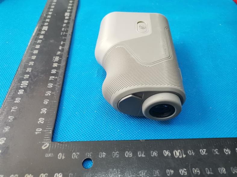
Click to zoom
Application Details
- Equipment Class
- DTS - Digital Transmission System
- Date of Grant
- May 16, 2021
- Application Purpose
- Original Equipment
- Date of Application
- May 15, 2021
- Equipment Note
- Rangefinder
- Frequency Range
- 2402.00000000 - 2480.00000000
- Country
- China
Documents & Files
Document Text
Text extracted from the exhibit documents filed with the FCC. Open a document above to read the original.
Users Manual
Search the App Store or Google Play Store for the Precision Pro Golf app. Follow the instructions in the app to pair the R1 Smart Rangefinder and utilize advanced features like MYSLOPE TM , Find My Precision Pro, and Wind Assist TM . Download the App Use the QR Code to download the Precision Pro Golf app. Follow the instructions in the app to pair your R1 Smart Rangefinder. AVAILABLE AT amazon.com/feedback WRITE A REVIEW AT Thank you FOR CHOOSING PRECISION PRO We believe golf is best played boldly, with the tools and tech that fit your style and your play. Our revolutionary R1 Smart Rangefinder provides the smartest, most personalized distance measurements in the game. If it isn’t personalized, it isn’t precise. THANKS10 USE CODE precisionprogolf.com YOUR NEXT PURCHASE OFF % OR SHARE WITH A FRIEND PRODUCT MANUAL This product works best when paired with the PRECISION PRO GOLF app. Please use the QR Code above to download the app and pair it with your rangefinder. DownLoad the app FCC Statement This equipment has been tested and found to comply with the limits for a Class B digital device, pursuant to part 15 of the FCC Rules. These limits are designed to provide reasonable protection against harmful interference in a residential installation. This equipment generates, uses and can radiate radio frequency energy and, if not installed and used in accordance with the instructions, may cause harmful interference to radio communications. However, there is no guarantee that interference will not occur in a particular installation. If this equipment does cause harmful interference to radio or television reception, which can be determined by turning the equipment off and on, the user is encouraged to try to correct the interference by one or more of the following measures: • Reorient or relocate the receiving antenna. • Increase the separation between the equipment and receiver. • Connect the equipment into an outlet on a circuit different from that to which the receiver is connected. • Consult the dealer or an experienced radio/TV technician for help. Caution: Any changes or modifications to this device not explicitly approved by manufacturer could void your authority to operate this equipment. This device complies with part 15 of the FCC Rules. Operation is subject to the following two conditions: (1) This device may not cause harmful interference, and (2) this device must accept any interference received, including interference that may cause undesired operation. RF Exposure Information The device has been evaluated to meet general RF exposure requirement. The device can be used in portable exposure condition without restriction. 1. Laser Lens 2. Optical Lens 3. Magnetic Grip 4. Mode/Screen Button 5. Power/Laser/Bluetooth Connect Button 6. Adjustable Eyepiece 7. Charging Port / Bluetooth Indicator 8. Slope On/Off Switch Product overview 1 2 6 3 4 5 7 8 The first-ever personalized slope calculation that creates an adjusted distance specific to you and your environment in the moment. IF IT ISN’T PERSONALIZED, IT ISN’T PRECISE. MYSLOPE TM is a game-changing level of accuracy applied to every course, club, and swing to give you a number that’s specific to you -- and no one else. • Launch angle • Ball speed • Spin rate • Temperature • Altitude • Humidity 1. Non Slope-Adjusted Laser Distance 2. Aiming Circle 3. MYSLOPE TM Indicator 4. Slope Adjusted Distance 5. Wind Assist TM 6. Yards/Meters Indicator 7. Battery Level Laser SCREEN 1 2 3 4 7 5 6 1 5 2 7 6 3 4 1. Center-of-Green Distance 2. Front-of-Green Distance 3. MYSLOPE TM Indicator 4. Back-of-Green Distance 5. Hole Number 6. GPS Indicator 7. Bluetooth Indicator GPS SCREEN Rangefinder quickstart GUIDE Download the PRECISION PRO GOLF app from the Apple App Store or the Google Play Store. 1: CONNECT Rangefinder quickstart GUIDE Turn on the rangefinder by pressing the POWER button. 2: Open the Precision Pro Golf app, go to the devices tab, and follow the pairing instructions to connect your R1 Smart Rangefinder. 3: Rotate the dial left or right on the adjustable eyepiece until the display appears sharply focused. 4: Rangefinder quickstart GUIDE Point the aiming circle at the target -- flag, tree, bunker, etc. -- then press the POWER button to “shoot your target.” 5: Rangefinder quickstart GUIDE The distance will appear on the screen. 6: Press the MODE button to see the Front-Center-Back measurements on the GPS Screen. (Press the MODE button again to return to the Laser Screen.) 7: The Rangefinder’s Screen will turn off after 8 seconds of inactivity. The bluetooth connection will disconnect after 30 minutes of inactivity. 8: ScreensScreens Press and release the MODE button to switch between the Laser Screen and the GPS Screen. 1: If a round of golf has been started in the Precision Pro Golf app, the GPS distances to the Front, Center, and Back of the green will appear on the GPS Screen. 2: Press and release the MODE button again to switch the display back to the Laser Screen. 3: Ensure your rangefinder is on the Laser Screen (Screen 1). 1: Press and hold the MODE button for six seconds until the Yards/ Meters indicator changes from Y to M, or vice versa. 2: Yards / MetersSlope Switch Slide the Slope Indicator switch on the side of the rangefinder forwards or backwards to turn slope on and off. 1: Slope is activated when the green is visible. Slope is turned off when the green is not visible. 2: OFF ON Open the Precision Pro Golf app and go to the DEVICES tab. 1: Under the R1 Smart Rangefinder, select “Find My Precision Pro.” 2: Find my Precision ProFind my Precision Pro The screen will show the location where you were last connected to your rangefinder. 3: Please note: you will need to have first connected you R1 and will need to have cell service for the feature to function properly. * PING RANGEFINDER Connection Successful Wind Assist TM Ensure your rangefinder is on the Laser Rangefinder Screen (Screen 1). Real-time wind data from our app is calcu…
Text truncated - open the document above for the full version.
Cover Letter(s)
Shenzhen Valueplus2 Electronic Corp.,Ltd. Room 12A, Building A, Zhongyu Green High Tech Industrial Park, Wenge Road, Gongming Street, Guangming New Area, Shenzhen, Guangdong, China Date: 2021-05-11 Dear Sir/Madam, We, Shenzhen Valueplus2 Electronic Corp.,Ltd. Hereby declares the following statement for Federal Communications Commission, PCB board, circuit, structure and internal of these model(s) are the same, Only model number is different for these model: Product name: Rangefinder Model no.: R1, RF-01, Nexus Slope Sincerely, Name/Title: Gong Wu/Manager Company: Shenzhen Valueplus2 Electronic Corp.,Ltd. Address: Room 12A, Building A, Zhongyu Green High Tech Industrial Park, Wenge Road, Gongming Street, Guangming New Area, Shenzhen, Guangdong, China Phone: +86 18923720211 E-Mail: [email protected]
Cover Letter(s)
CONFIDENTIALITY REQUEST for Certification Service in USA Federal Communication Commission Equipment Authorization Division, Application Processing Branch 7435 Oakland Mills Road Columbia, MD 21046 Date: 2021/05/11 TO WHOM IT MAY CONCERN Pursuant to Paragraphs §0.457 and 0.459 of the Commission’s Rules (47 C.F.R.) and Section §552(b)(4) of the Freedom of Information Act, we requests confidentiality for the following products: FCC ID Model name 2AXLU-R1 R1 For the product stated above, we request that the following information be held confidential; Exhibits Long-Term Confidentiality Short-Term Confidentiality Short-Term Confidentiality Days External Photos Internal Photos Block Diagram Schematics Test Setup Photos User’s Manual Parts List Tune Up Operational Descriptions The long-term confidentiality exhibits contain our trade secrets and proprietary information that could be of benefit to our competitors. The short-term confidentiality on the basis of ensuring that business sensitive information remains confidential until the actual marketing of our new device. If you have any questions, please feel free to contact me at the address shown below. Sincerely, Name/Title: Gong Wu/Manager Company: Shenzhen Valueplus2 Electronic Corp.,Ltd. Address: Room 12A, Building A, Zhongyu Green High Tech Industrial Park, Wenge Road, Gongming Street, Guangming New Area, Shenzhen, Guangdong, China Phone: +86 18923720211 E-Mail: [email protected]
Cover Letter(s)
Shenzhen Valueplus2 Electronic Corp.,Ltd. Room 12A, Building A, Zhongyu Green High Tech Industrial Park, Wenge Road, Gongming Street, Guangming New Area, Shenzhen, Guangdong, China Federal Communications Commission Authorization and Evaluation Division Equipment Authorization Branch 7435 Oakland Mills Road Columbia, MD 21046 2021/05/11 To whom it may concern: We, Shenzhen Valueplus2 Electronic Corp.,Ltd. the undersigned, hereby authorize Eurofins Product Service GmbH to act on our behalf in all matters relating to applications for equipment authorization FCC ID: 2AXLU-R1 including the signing of all documents related to these matters. Any and all acts carried out by Eurofins Product Service GmbH on our behalf shall have the same effect as acts of our own. We also hereby certify that no party to this application is subject to a denial of benefits, including FCC benefits, pursuant to Section 5301 of the Anti-Drug Abuse Act of 1988, 21 U.S.C. 862. Sincerely, Name/Title: Gong Wu/Manager Company: Shenzhen Valueplus2 Electronic Corp.,Ltd. Address: Room 12A, Building A, Zhongyu Green High Tech Industrial Park, Wenge Road, Gongming Street, Guangming New Area, Shenzhen, Guangdong, China Phone: +86 18923720211 E-Mail: [email protected]
External Photos
FCC ID: 2AXLU-R1 External Photos of the EUT FCC ID: 2AXLU-R1 FCC ID: 2AXLU-R1
ID Label/Location Info
FCC ID: 2AXLU-R1 Label and Location Size: L: 4.0cm*W: 3.0cm Label and Location Rangefinder Model No.: R1 FCC ID : 2AXLU-R1 This device complies with part 15 of the FCC Rules. Operation is subject to the following two conditions: (1) This device may not cause harmful interference, and (2) this device must accept any interference received, including interference that may cause undesired operation.
Internal Photos
FCC ID: 2AXLU-R1 Internal Photos of the EUT FCC ID: 2AXLU-R1 FCC ID: 2AXLU-R1 FCC ID: 2AXLU-R1 FCC ID: 2AXLU-R1
RF Exposure Info
RF Exposure evaluation FCC ID: 2AXLU-R1 1.1. Applicable Standard According to §1.1307(b)(1), systems operating under the provisions of this section shall be operated in a manner that ensures that the public is not exposed to radio frequency energy level in excess of the Commission’s guidelines. According to §1.1310 and §2.1093 RF exposure requirement KDB447498 v06: Mobile and Portable Devices RF Exposure Procedures and Equipment Authorization Policies 1.2. Requirement According to KDB447498 D01 General RF Exposure Guidance v06 Section 4.3.1 Standalone SAR test exclusion considerations: “Unless specifically required by the published RF exposure KDB procedures, standalone 1-g head or body and 10-g extremity SAR evaluation for general population exposure conditions, by measurement or numerical simulation, is not required when the corresponding SAR Test Exclusion Threshold condition, listed below, is satisfied. These test exclusion conditions are based on source-based time-averaged maximum conducted output power of the RF channel requiring evaluation, adjusted for tune-up tolerance, and the minimum test separation distance required for the exposure conditions.22 The minimum test separation distance is determined by the smallest distance from the antenna and radiating structures or outer surface of the device, according to the host form factor, exposure conditions and platform requirements, to any part of the body or extremity of a user or bystander (see 5) of section 4.1). To qualify for SAR test exclusion, the test separation distances applied must be fully explained and justified by the operating configurations and exposure conditions of the transmitter and applicable host platform requirements, typically in the SAR measurement or SAR analysis report, according to the required published RF exposure KDB procedures. When no other RF exposure testing or reporting is required, a statement of justification and compliance must be included in the equipment approval, in lieu of the SAR report, to qualify for the SAR test exclusion. When required, the device specific conditions described in the other published RF exposure KDB procedures must be satisfied before applying these SAR test exclusion provisions; for example, handheld PTT two-way radios, handsets, laptops & tablets etc.23 “ [(max. power of channel, including tune-up tolerance, mW)/ (min. test separation distance, mm)] · [√f (GHz)] ≤ 3.0 for 1-g SAR and ≤ 7.5 for 10-g extremity SAR, where: • f (GHz) is the RF channel transmit frequency in GHz • Power and distance are rounded to the nearest mW and mm before calculation • The result is rounded to one decimal place for comparison • 3.0 and 7.5 are referred to as the numeric thresholds in the step 2 below The test exclusions are applicable only when the minimum test separation distance is ≤ 50 mm and for transmission frequencies between 100 MHz and 6 GHz. When the minimum test separation distance is < 5 mm, a distance of 5 mm according to 5) in section 4.1 is applied to determine SAR test exclusion. 1.3. Manufacturing tolerance GFSK(Peak) Channel Channel 00 Channel 19 Channel 39 Target (dBm) 4.0 4.0 4.0 Tolerance ±(dB) 1.0 1.0 1.0 Page 2 of 2 2. E v a l u a t i o n R e s u l t Evaluation Results Band/Mode f (GHz) Antenna Distance (mm) RF output power (including tune-up tolerance) SAR Test Exclusion Threshold SAR Test Exclusion dBm mW BT 2.480 5 5.0 3.1623 0.9929<3.0 Yes 3. C o n c l u s i o n The measurement results comply with the FCC Limit per 47 CFR 2.1093 for the uncontrolled RF Exposure and SAR Exclusion Threshold per KDB 447498 v06 .....................End of Report.........................
Test Report
Shenzhen Global Test Service Co.,Ltd. No.7-101 and 8A-104, Building 7 and 8, DCC Cultural and Creative Garden, No.98, Pingxin North Road, Shangmugu Community, Pinghu Street, Longgang District, Shenzhen, Guangdong FCC PART 15 SUBPART C TEST REPORT FCC PART 15.247 Report Reference No. ..................... : FCC ID. ............................................ : GTS20210315017-1-1 2AXLU-R1 Compiled by ( position+printed name+signature) .. : File administrators Jimmy Wang Supervised by ( position+printed name+signature) .. : Test Engineer Aaron Tan Approved by ( position+printed name+signature) .. : Manager Jason Hu Date of issue ..................................... : May 11, 2021 Representative Laboratory Name .: Shenzhen Global Test Service Co., Ltd. Address ............................................ : No.7-101 and 8A-104, Building 7 and 8, DCC Cultural and Creative Garden, No.98, Pingxin North Road, Shangmugu Community, Pinghu Street, Longgang District, Shenzhen, Guangdong Applicant’s name ............................ : Shenzhen Valueplus2 Electronic Corp.,Ltd. Address ............................................ : Room 12A, Building A, Zhongyu Green High Tech Industrial Park, Wenge Road, Heshuikou Community, Gongming Street, Guangming New Area, Shenzhen, Guangdong, China Test specification ...........................: Standard ........................................... : FCC Part 15.247 Shenzhen Global Test Service Co.,Ltd. All rights reserved. This publication may be reproduced in whole or in part for non-commercial purposes as long as the Shenzhen Global Test Service Co.,Ltd. is acknowledged as copyright owner and source of the material. Shenzhen Global Test Service Co.,Ltd. takes no responsibility for and will not assume liability for damages resulting from the reader's interpretation of the reproduced material due to its placement and context. Test item description .....................: Rangefinder Trade Mark ....................................... : Precision Pro Manufacturer .................................... : Shenzhen Valueplus2 Electronic Corp.,Ltd. Model/Type reference....................... : R1 Listed Models .................................. : RF-01, Nexus Slope Modulation ....................................... : GFSK Frequency .......................................... From 2402MHz to 2480MHz Ratings ............................................. : DC 3.70V From Battery and DC 5V From external circuit Result................................................ : PASS Report No.: GTS20210315017-1-1 Page 2 of 35 T E S T R E P O R T Test Report No. : GTS20210315017-1-1 May 11, 2021 ____________________________________________________________________________________ Date of issue Equipment under Test : Rangefinder Model /Type : R1 Listed Models : RF-01, Nexus Slope Applicant : Shenzhen Valueplus2 Electronic Corp.,Ltd. Address : Room 12A, Building A, Zhongyu Green High Tech Industrial Park, Wenge Road, Heshuikou Community, Gongming Street, Guangming New Area, Shenzhen, Guangdong, China Manufacturer : Shenzhen Valueplus2 Electronic Corp.,Ltd. Address : Room 12A, Building A, Zhongyu Green High Tech Industrial Park, Wenge Road, Heshuikou Community, Gongming Street, Guangming New Area, Shenzhen, Guangdong, China Test Result: PASS The test report merely corresponds to the test sample. It is not permitted to copy extracts of these test result without the written permission of the test laboratory. Report No.: GTS20210315017-1-1 Page 3 of 35 Contents 1 T E S T S T A N D A R D S ................................................................. 4 2 S U M M A R Y ............................................................................ 5 2.1 General Remarks 5 2.2 Product Description 5 2.3 Equipment Under Test 5 2.4 Short description of the Equipment under Test (EUT) 5 2.5 EUT operation mode 6 2.6 Block Diagram of Test Setup 6 2.7 Related Submittal(s) / Grant (s) 6 2.8 Modifications 6 3 T E S T E N V I R O N M E N T .............................................................. 7 3.1 Address of the test laboratory 7 3.2 Test Facility 7 3.3 Environmental conditions 7 3.4 Summary of measurement results 8 3.5 Statement of the measurement uncertainty 8 3.6 Equipments Used during the Test 9 4 T E S T C O N D I T I O N S A N D R E S U L T S ........................................... 10 4.1 AC Power Conducted Emission 10 4.2 Radiated Emissions and Band Edge 13 4.3 Maximum Peak Output Power 19 4.4 Power Spectral Density 20 4.5 6dB Bandwidth 22 4.6 Out-of-band Emissions 24 4.7 Antenna Requirement 27 5 T E S T S E T U P P H O T O S O F T H E E U T ......................................... 28 6 P H O T O S O F T H E E U T ........................................................... 29 Report No.: GTS20210315017-1-1 Page 4 of 35 1 T E S T S T A N D A R D S The tests were performed according to following standards: FCC Rules Part 15.247: Frequency Hopping, Direct Spread Spectrum and Hybrid Systems that are in operation within the bands of 902-928 MHz, 2400-2483.5 MHz, and 5725-5850 MHz. ANSI C63.10-2013: American National Standard for Testing Unlicensed Wireless Devices KDB558074 D01 V03r05: Guidance for Performing Compliance Measurements on Digital Transmission Systems (DTS) Operating Under §15.247 Report No.: GTS20210315017-1-1 Page 5 of 35 2 S U M M A R Y 2.1 General Remarks Date of receipt of test sample : Mar. 29, 2021 Testing commenced on : Mar. 29, 2021 Testing concluded on : May 11, 2021 2.2 Product Description Product Description: Rangefinder Model/Type reference: R1 Power supply: DC 3.70V From Battery and DC 5V From external circuit Adapter information (Auxiliary test suppied by test Lab) Mode:EP-TA20CBC Input:AC100-240V-50/60Hz,0.5A Output:DC 5V,2A Testing sample ID: GTS20210315017-1-1-1# (Engineer sample), GTS20210315017-1-1-2# (Normal sample) Bluetooth BLE Supported type: Bluetooth low Energy Modulation: GFSK Operation frequency: 2402MHz to 2480MHz Channel number: 40 Channel separatio…
Text truncated - open the document above for the full version.
Test Setup Photos
FCC ID: 2AXLU-R1 Test Setup Photos of the EUT Test Setup Photo(s) of Radiated Emissions Measurement Fig. 1 Fig. 2 FCC ID: 2AXLU-R1 Test Setup Photo of Line Conducted Emissions Measurement
Contact Information
Applicant
Gong Wu
Test Firm
Shenzhen Global Test Service Co., Ltd.Simon Hu
[email protected]86-137-286-828-40
Technical Specifications
| # | Rule Parts | Frequency Range | Power Output |
|---|---|---|---|
| 1 | 15C | 2.40 GHz - 2.48 GHz | 3.10 mW |
Other Applications from Shenzhen Valueplus2 Electronic Corp.,Ltd.
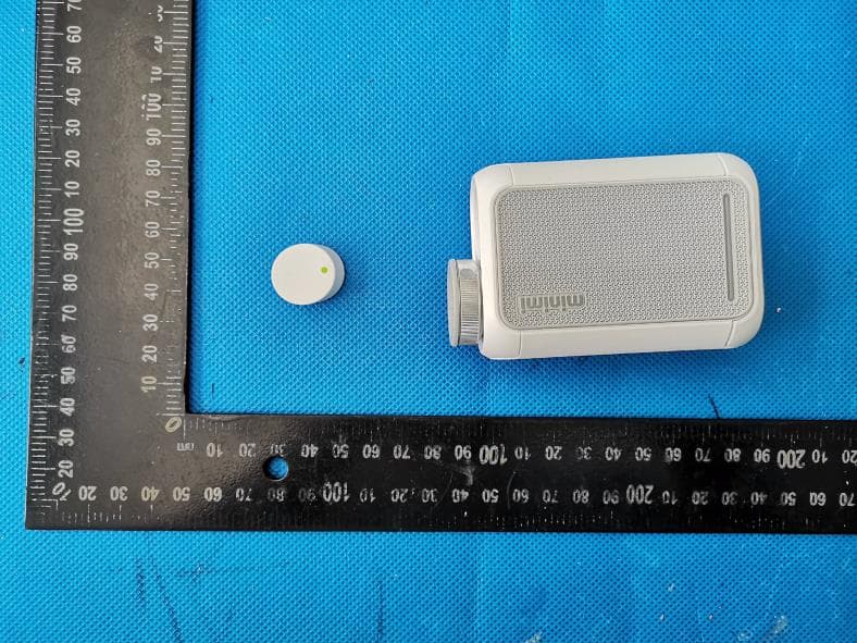
2AXLU-MINIMI
Sep 23, 2020rangefinder
Equipment Class
DSC - Part 15 Security/Remote Control Transmitter